

Trannergy PVI1300TL, PVI1800TL, PVI2300TL, PVI2700TL, PVI3200TL User Manual
...
User Manual
PVI1300/1800/2300/2700/3000/3200/4000/4600/5400TL

User Manual 1
Contents
Copyright Declaration ............................................................................................................... 3
1. Introduction
........................................................................................................................... 4
1.1. Introduction
.................................................................................................................... 4
1.2. How to Use this manual
................................................................................................. 4
1.3. Applied Designations (Warning, Caution, Note)
........................................................... 4
1.4. Important Safety Information
......................................................................................... 5
1.5. General Safety Rules for Working on Electrical Equipment
.......................................... 6
1.6. System Sizing
................................................................................................................. 7
1.7. DC-switch
....................................................................................................................... 7
2. Technical Description of Inverters
........................................................................................ 8
2.1. Mechanical design
.......................................................................................................... 8
2.2. Electrical system design
................................................................................................. 9
3. Operation Mode Definition
................................................................................................. 11
3.1. Waiting mode
............................................................................................................... 11
3.2. Connecting mode
.......................................................................................................... 11
3.3. Normal mode
................................................................................................................ 11
3.4. Fault mode
.................................................................................................................... 11
4. Installation and startup
........................................................................................................ 13
4.1. Installation precaution
.................................................................................................. 13
4.2. Installing the inv e r ter
.................................................................................................... 16
4.3. Electrical connection
.................................................................................................... 18
4.3.1 Connection to the grid (AC) for Product A
............................................................ 19
4.3.2 Connection to the grid (AC) for Product B
............................................................ 22
4.3.3 Connection to the PV generator (DC) for Product A&B
........................................ 22
4.4. Run the inverter
............................................................................................................ 25
5. Human Machine Interface
................................................................................................... 26
5.1. Control Panel
................................................................................................................ 26
5.2. LCD Functions ............................................................................................................. 27
5.3. Language Settings
........................................................................................................ 27

2 User Manual
5.4. Auto Test Settings ........................................................................................................ 28
5.5. Power Factor Settings
................................................................................................... 30
5.6. Power Limit Settings
.................................................................................................... 30
6. Communication and Monitoring
......................................................................................... 31
6.1. Communication Interfaces
............................................................................................ 31
6.2. Communication
............................................................................................................ 31
6.2.1. RS-232 Communication for single inverter type
................................................... 31
6.2.2. RS-485 Communication for Several inverters
....................................................... 32
6.2.3. Wireless
................................................................................................................. 33
6.3. Monitoring
.................................................................................................................... 33
7. Service and repair
................................................................................................................ 34
7.1. Safety during service and repair
................................................................................... 34
7.2. Troubleshooting
............................................................................................................ 34
8. Technique specification
....................................................................................................... 36
8.1. Electrical Specification
................................................................................................. 36
8.1.1. Input Specification
................................................................................................. 36
8.1.2. Output Specification
.............................................................................................. 37
8.1.3. General Data
.......................................................................................................... 37
9. Qualification
........................................................................................................................ 39
10. Contact Information
........................................................................................................... 40
Appendix A: FAQ (Frequently asked questions)
.................................................................... 41
Appendix B: Abbreviation
...................................................................................................... 42

User Manual 3
Copyright Declaration
The copyright of this manual belongs to Trannergy Co., Ltd. Any corporation or
individual should not plagiarize, partially copy or fully copy it (including software,
etc.), and no reproduction or distribution of it in any form or by any means. All rights
reserved. Trannergy reserves the right of final interpretation. This manual is subject to
change according to user’s or customer’s feedback. Please check latest version at:
http://www.trannergy.com.
4 User Manual
1. Introduction
1.1. Introduction
This manual describes Trannergy solar inverters PVI1300TL,PVI1800TL ,PVI2300TL,
PVI2700TL,PVI3000TL,PVI3200TL, PVI4000TL, PVI4600TL and PVI5400TL.
These
products are among the most technologically advanced and efficient inverters on
the market and are designed to ensure a stable power supply for many years.
The PVI inverter is a transformerless based inverter.
1.2. How to Use this manual
Please read the saf ety instructions in this manual first. Throughout the manual it
is assumed that the reader is familiar with AC and DC installations and knows the
rules and regulations for electrical equipment and for connecting it to the utility
AC grid. It is especially important to be familiar with the general safet y rules for
working with electrical equipment.
1.3. Applied Designations (Warning, Caution, Note)
Throughout the manual important information is shown at different levels
depending on the character of the information, as shown here:
Safety information important for human safety. Violation of
warnings may result in injury to persons or death.
Information important for the protection of property. Violation
of this type of information may cause damage and
loss of
property.
Useful additional information or “Tips and Tricks" on specific
subjects.
User Manual 5
1.4. Important Safety Information
Read this before installing, operating or maintaining the inverter.
Before installation:
Check for damage to inverter and packaging. If you are in doubt,
please contact your supplier before installing the inverter. Check
the voltages of the solar modules and make sure t hey are within
the limits of the Trannergy inverter specifications before
connecting them to the inverter.
Installation:
O
nly trained and authorized personnel familiar with local
electrical codes may install the inverter. For optimum safety,
please follow the steps described in this manual. Keep in mind
that the inverter has two voltage carrying sides, the PV input and
the AC grid.
Disconnecting the inverter:
Always disconnect the AC line first! Afterwards disconnect the
PV lines. Note that the inverter can still be charged with very
high voltages at hazardous level s even when it is disconnected
from grid/mains and solar modules. Wait at least 15 min. before
proceeding, after having disconnected from grid and PV panels.
operating the inverter:
Before connectin g the AC grid t o t he i nve rt er, make sure that the
installation cover
is mounted again. The inverter must not be
open during operation.
Maintenance and modification:
Only authorized personnel are allowed to repair or modify the
inverter. To ensure
optimum safety for user and environment,
only the original spare parts available from your supplier should
be used.
Functional safety parameters:
Unauthorized changes of functional safety parameters may cause
injury or accidents to people or inverter. Additionally it will lead
to the cancelling of all inverter operating approval certificates.
The Trannergy inverters in the PVI range are all designed
according to the German VDE0126-1-1standard.
If non-
original spare parts are used, the compliance with CE
guidelines in respect of electrical
safety, EMC and machine
safety is not guaranteed.
6 User Manual
1.5. General Safety Rules for Working on Electrical Equipme nt
All persons installing, maintaining or servicing inverters should be trained in and
have experience with the general safety rules to be observed when working on
electrical equipment.
Installation and service personnel should also be familiar with local requirements,
rules and regulations as well as safety requirements.
To provide a general guideline for safety precautions, five well-known and
widely accepted rules are repeated below. The list should by no means be
considered as exhaustive.
The
person performing work on electrical equipment is
responsible for the safety of persons and property!
Disconnecting
Disconnect all cables supplying voltage to the working place
before starting an y work. Please not e that a lack o f volta ge is no
guarantee that disconnection has been performed.
Protecting against reconnection
Prevent the system from reconnecting by marking, closing or
locking off the work area. Unintentional reconnection may result
in severe accidents.
Checking that system is voltage free
Ascertain conclusively by means of a voltage tester that the
system is voltage free. Check all terminals to ensure that the
system is voltage free (on each individual conductor).
Covering adjacent voltage-carrying components and
preventing persons from gaining access to them
Cover up all voltage-carrying system components tha t can harm
you while working. Make sure that danger areas are clearly
marked.

User Manual 7
1.6. System Sizin g
When dimensioning a photovoltaic system, it must be ensured
that the open circuit voltage of the PV string never exceeds the
maximum permissible input voltage of 600V DC. The PV string
open circuit voltage during parallel string operation is 450V DC
(PVI1300TL/PVI1800TL),500V (PVI2300TL /PVI2700TL
/PVI3000TL) and 550V(PVI3200TL /PVI4000TL /PVI4600TL
/PVI5400TL) respectively. Higher voltages may result in
permanent damage to the inverter.
In Europe, the PV string open circuit voltage is normally calculated at a module
temperature of M10NC or M20NC depending on the location.
The selection of PV string output should be based on the optimum utilization of
the invested capital compared to the expected annual energy yield from the
system. This optimization depends on local weather conditions and should be
considered in each individual case.
The inverter incorporates an input power limiting device, which automatically
keeps the power at levels that are safe for the inverter. The limitation depends
mainly on internal and ambient temperatures. The limitation is calculated
continuously and always allows the maximum possible amount of energy to be
produced.
Please use the tool supplied by Trannergy when dimensioning a photovoltaic
system.
1.7. DC-switch
On1y trained and authorized personnel familiar with local
electrical codes may perform serv
ice or maintenance on the
inverter. Before opening the inverter:
1) Disconnect AC grid.
2) Disconnect DC power.
3) Remove both AC and DC 1ines.
1) To switch OFF a ll power supply from the PV panels turn the DC-switch to
OFF (O).
2) To switch ON power supply from the PV panel turn the DC-switch to ON (I).
To ensure the functiona1ity of the DC-switch, a11 switches shou1d be switched
on and off (by turning the switch to on and off positions ten times) once a year, to
c1ean the contacts.
8 User Manual
2. Technical Description of Inverters
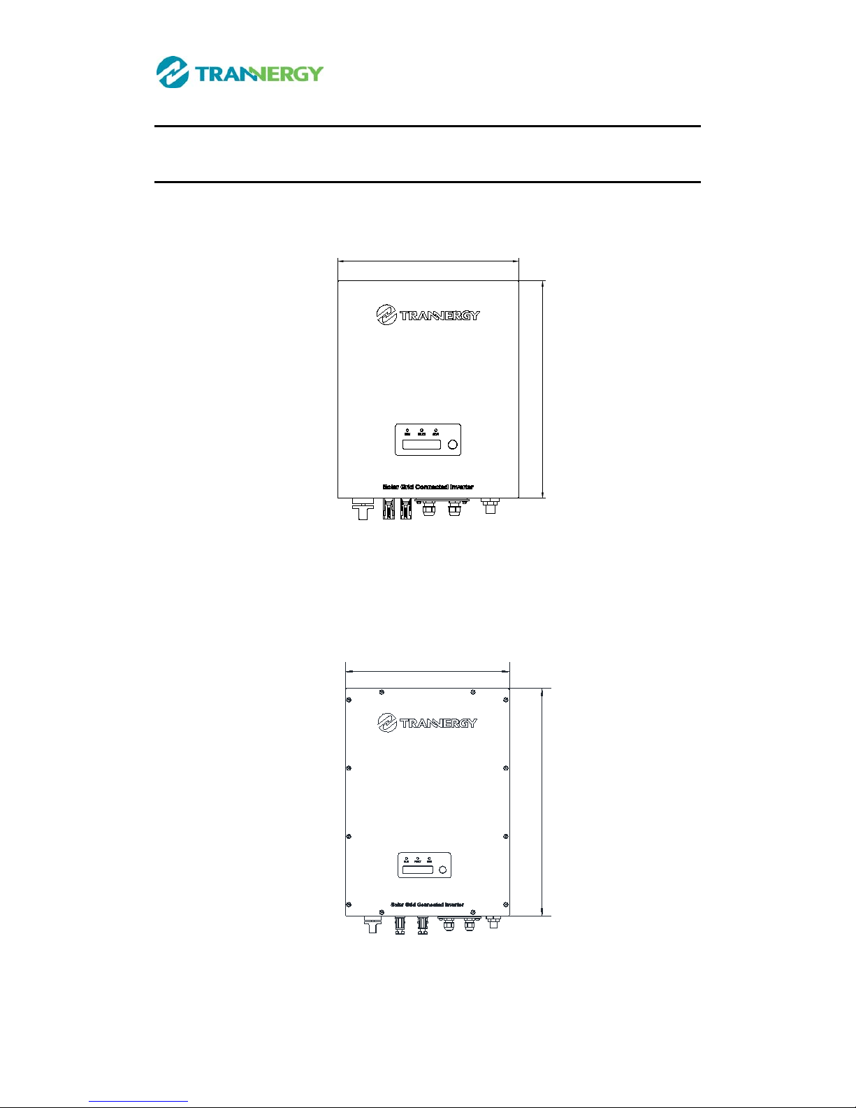
2.1. Mechanical design
Figure 2-1 shows the outline dimensions of PVI1300/1800/2300/2700/3000TL:
320
380
Figure 2-1
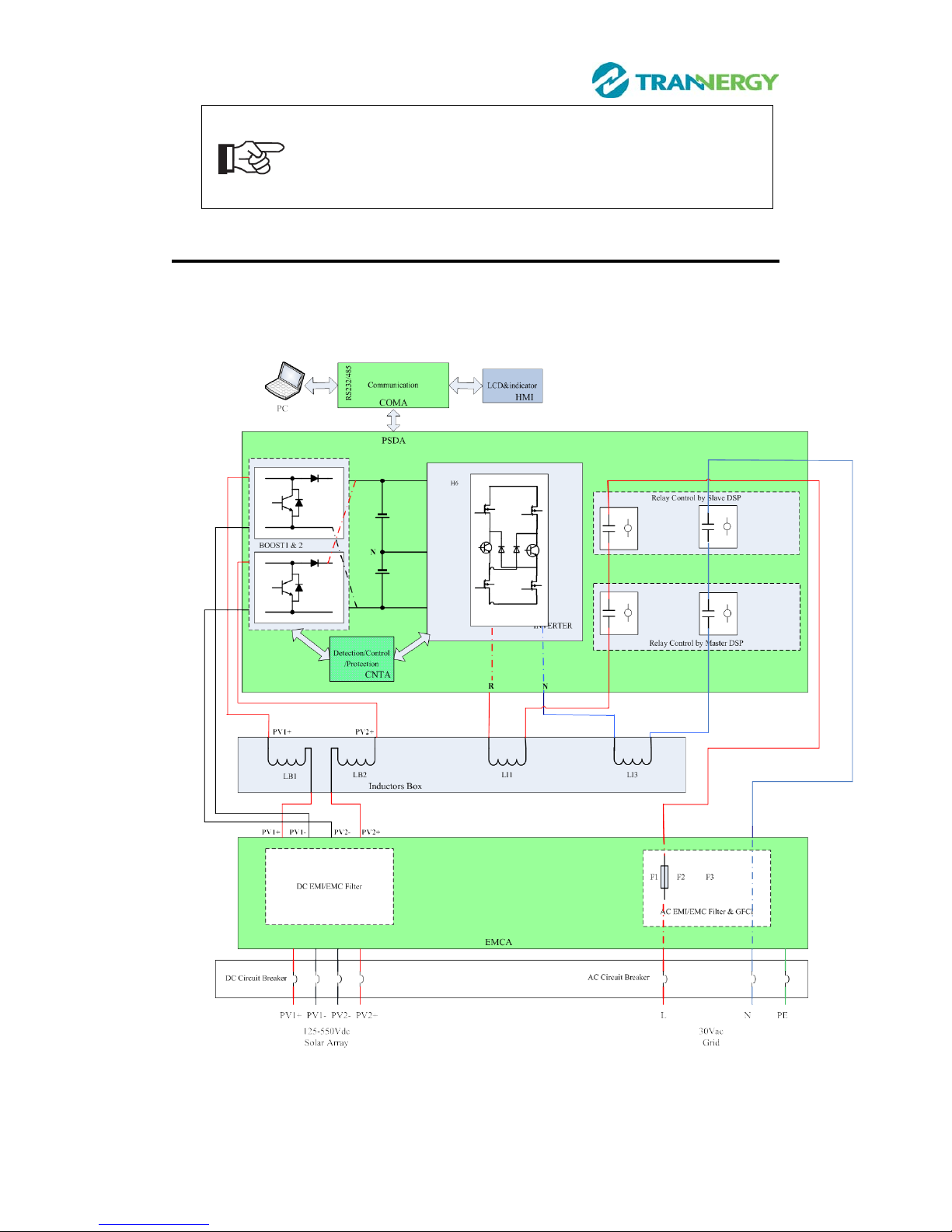
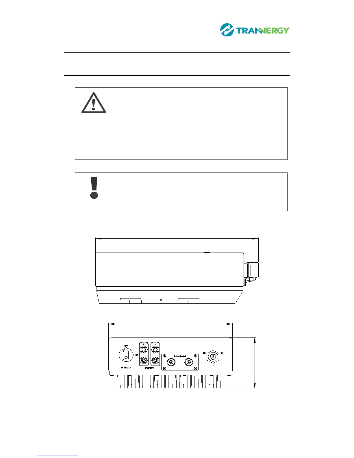
Figure 2-2 shows the outline dimensions of PVI3200/4000/4600/5400TL:
500
360
Figure 2-2
User Manual 9
Note: The AC output terminal is most length part at the bottom
of inverter, so take care of the AC output terminals, do not make
it stand on the ground or other materials while moving or lifting
the inverters otherwise will make terminal damaged.
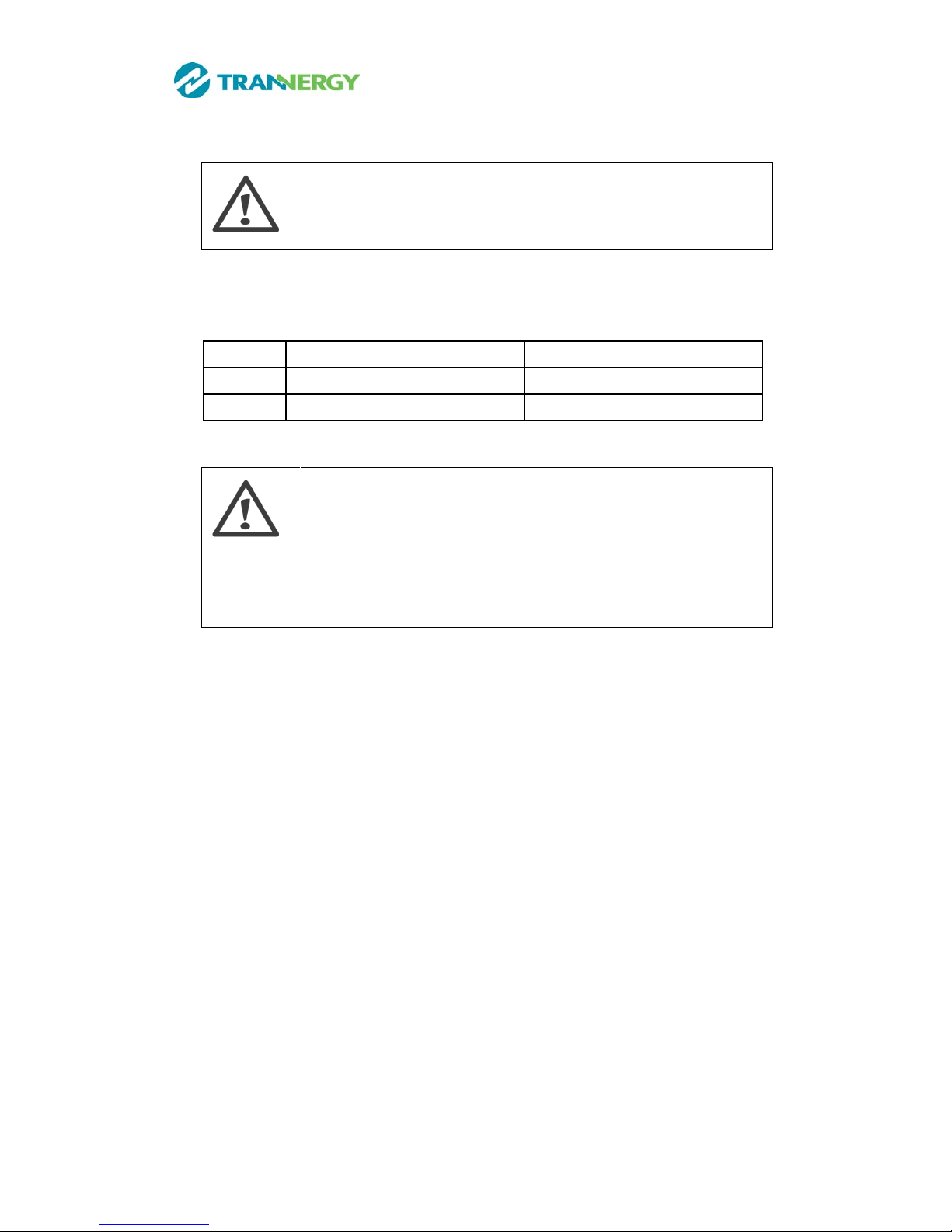
2.2. Electric al sy ste m design
Figure 2-3 shows the wiring diagram of the whole PVI1300/1800 /2300 /2700
/3000 / 3200/4000/ 4600/5400TL systems.
Figure 2-3 wiring diagram of the whole
PVI1300/1800/2300/2700/3000/3200/4000/4600/5400TL system
10 User Manual
We recommend a 32A DC Breaker located at the input of the DC input, and a
32A AC Breaker located at the output of the AC part.
Notes:
When choose the breaker, please call your installer for technique
support
For the input and output wire selection, we recommend UL1015 wire, please see
the following table.
Model PVI1300/1800/2300/2700/3000/3200TL PVI4000/4600/5400TL
DC input 14AWG 12AWG
AC output 14AWG 12AWG
Notes:
Before install the inverter, please firstly check the polarity of the
PV side, and a wrong polarity to the inverter may lead to a
permanent damage
T
he above recommended wire already consider the maximum
work current and degrading

User Manual 11
3. Operation Mode Definition
The inverter has four standard operation modes.
3.1. Waiting mode
In waiting mode, the inverter is ready to switch into connecting mode. As
decision variable the input voltage of the PV generator is used. Inverter is waiting
to checking when output DC voltage from PV panels is greater than 100V ( lowest
start-up voltage) but less than 150V (lowest operating voltage). If the input
voltage exceeds 150V, the inverter shifts from "standby" to "connecting", or
continues into the operation model OFF" if the PV voltage drops.
3.2. Connecting mode
After performing the syst em test s, whi ch check w hethe r all conne cti on conditions
are met, the inverter goes from waiting mode to connecting mode. During the
specified cut-in time, the inverter continues testing the system values and
connects the inverter to the grid if the system tests are okay. The minimum cut-in
time is specified by the supplier and authorities and can vary from region to
region.
3.3. Normal mode
In this mode, the inverter is connected to the grid and supplies power to the grid.
Inverter begins to operate normally with green light on. Meanwhile, feedback
energy to grid, LCD displays present output power, and inverter will stop
feedbacks power to grid when PV power is not enough. The inverter is only
disconnected from the grid in case of abnormal grid conditions or when PV
power is not available.
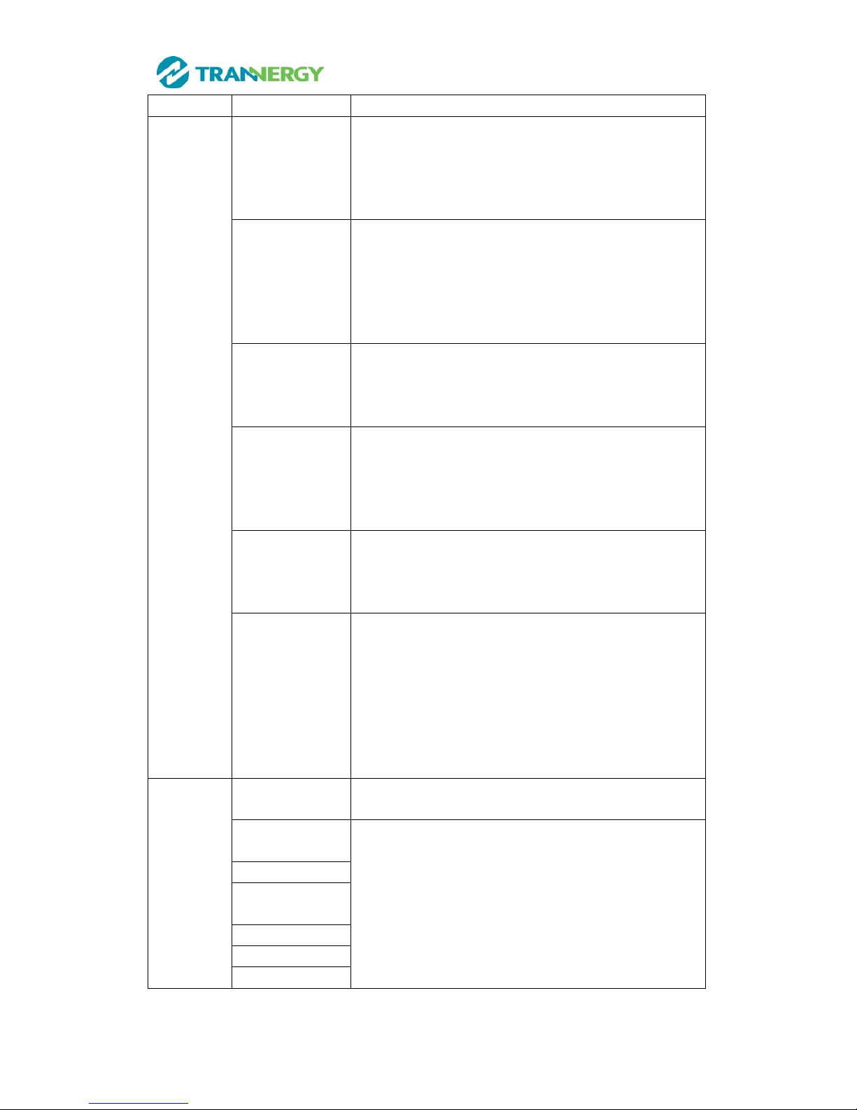
3.4. Fault mode
If the red LED on the front panel light up, the inverter enters the fault mode. The
following solutions for trouble shooting are recommended:
12 User Manual
LCD display Possible actions
Resumable
Fault
Isolation Fault 1. Check the impe dance between PV (+)&PV(-) and
the inverter is earthed. T
he impedance must be
greater than 2MΩ
2. Check whether the AC end has contacted with
earth
Ground Fault 1. The ground current is too high
2. After cutting off the AC end connection, unplug
the inputs from the PV generator and check the
peripheral AC system.
3. After the cause is clear ed, re-plu g the PV generator
and AC connection, and check PV-Inverter status.
Grid Fault
Fac Over Range
Vac Over Range
1. Wait for a moment, if the grid returns to normal,
PV-Inverter aut om ati cal l y rest art s.
2. Make sure grid voltage and frequency meet the
specifications.
Utility Loss 1. Grid is not connected.
2. Check grid connection cables.
3. Check grid usability.
4. If grid is ok, the problem persists, maybe the fuse
in the inverter is open, please call the service.
Over
Temperature
1. The internal temperature is higher than specified
normal value.
2. Find a way to reduce the ambient temperature or
move the inverter to cooler environment.
PV over voltage 1. Check the open circuit voltage of the PV
generator, see if it is greater than or too close to
450VDC (for PVI1300TL/PVI1800TL) or
500VDC (for PVI2300TL /PVI2700TL
/PVI3000TL)
2. If PV voltage is less than 450VDC or 500VDC,
and the problem still occurs, please call the
service.
Permanent
Fault
Consistent Fault Disconnect PV (+) or PV(-) from the input, restart the
inverter.
Relay-Check
Fail
1. Disconnect all PV (+) or PV (-)
2. W ait for a few seconds.
3. After the LCD switch es off, reconnect and check
again.
4. If the problems remain, please call the service.
DC INJ High
EEPROM R/W
Fail
SCI Failure
AC HCT Fault
GFCI Failure
User Manual 13
4. Installation and startup
4.1. Installation precaution
Danger!
Danger of lethal injury due to fire or explosion!
The Trannergy inverter may become hot in normal operation.
Do not install the Trannergy inverter on easily flammable
materials and where flammable materials are stored.
Do not install the Trannergy inverter where there is a risk of
explosion.
Caution!
Danger of burns from hot housing components!
Install the Trannergy inverter at a proper place where it cannot
be touched unintentional.
Dimensions for PVI1300/1800TL/PVI2300TL/PVI2700TL/PVI3000TL:
418
320
143
Figure 4-1
Dimensions for PVI3200TL/ PVI4000TL/PVI4600TL/PVI5400TL:
 Loading...