

Trango brodband TrangoLINK-10-EXT Professional Installation Manual

TrangoLINK-10-EXT™
Wireless Ethernet Bridge
PROFESSIONAL INSTALLATION GUIDE

RU Antenna Alignment
TrangoLINK-10-EXT Professional Installation Guide
Overview
This manual covers basic configuration and installation of the TrangoLINK-10-EXT system which consists of two
radios, P5830S-MU-EXT (Master Unit) and P5830S-RU-EXT (Remote Unit). Since these devices require manual
maximum power limit settings (for 5.25-5.35 GHz U-NII band operation only), they are classified by the FCC as a
professional install devices. To be in compliance with FCC guidelines, the radios must be installed with one of
several approved antennas listed in this document.
The P5830S-MU-EXTR and P5830S-RU-EXT are currently FCC certified for use with three external antennas.
Antenna Part # Description Gain
AD5830-24-D 18” DSS Dish 24 dBi
AD5830-23-D 15” Flat Panel 24 dBi
SPD3-5.2 3’ Dish from Radiowaves 31 dBi
The P5830S-MU-EXT Master Unit works in conjunction with the P5830S-RU-EXT Remote Unit. Please see the
TrangoLINK-10 User Manual for general information on overall system implementation, configuration, and
management of these radios. The TrangoLINK-10 User Manual also covers many important aspects of radio
configuration and management which is applicable to the TrangoLINK-10-EXT.
FCC Information
This device complies with Part 15 of FCC Rules and Regulations. Operation is subject to the following two
conditions: (1) This device may not cause harmful interference and (2) this device must accept any interference
received, including interference that may cause undesired operation.
This equipment has been tested and found to comply with the limits for a Class B digital device, pursuant to Part 15
of the FCC Rules. These limits are designed to provide reasonable protection against harmful interference in a
residential installation. This equipment generates, uses, and can radiate radio-frequency energy and, if not installed
and used in accordance with these instructions, may cause harmful interference to radio communications. However,
there is no guarantee that interference will not occur in any particular installation. If this equipment does cause
harmful interference to radio or television reception, which can be determined by turning the equipment off and on,
the user is encouraged to correct the interference by one of more of the following measures:
1) Reorient the antenna;
2) Increase the separation between the affected equipment and the unit;
3) Connect the affected equipment to a power outlet on a different circuit from that which the receiver is
connected to;
4) Consult the dealer and/or experienced radio/TV technician for help.
FCC ID: NCYM5830SSUEXT
Canada: to be announced
IMPORTANT NOTE:
Intentional or unintentional changes or modifications must not be made unless under the express consent of the
party responsible for compliance. Any such modifications could void the user’s authority to operate the equipment
and will void the manufacturer’s warranty. To comply with FCC RF exposure requirements, the following antenna
installation and device operating configurations must be satisfied. The antenna for this unit must be fixed and
mounted on outdoor permanent structures with a separation distance of at least two meters from all persons.
Furthermore, it must not be co-located or operating in conjunction with any other antenna or transmitter.
Warranty Information
Radios from Trango Broadband Wireless are warranted from one year from date of purchase. Please see
www.trangobroadband.com
Trango Broadband Wireless – Rev. A
for complete description of warranty coverage and limitations.
Page
2
RU Antenna Alignment
TrangoLINK-10-EXT Professional Installation Guide
General Information
Contents
Each TrangoLINK-10-EXT kit comes equipped with a Master Unit (MU) and Remote Unit (RU), two power-overEthernet (PoE) J-Boxes, two AC adapters, and two mounting kits. The MAC Address and Serial # are printed on a
label on the back of the radio.
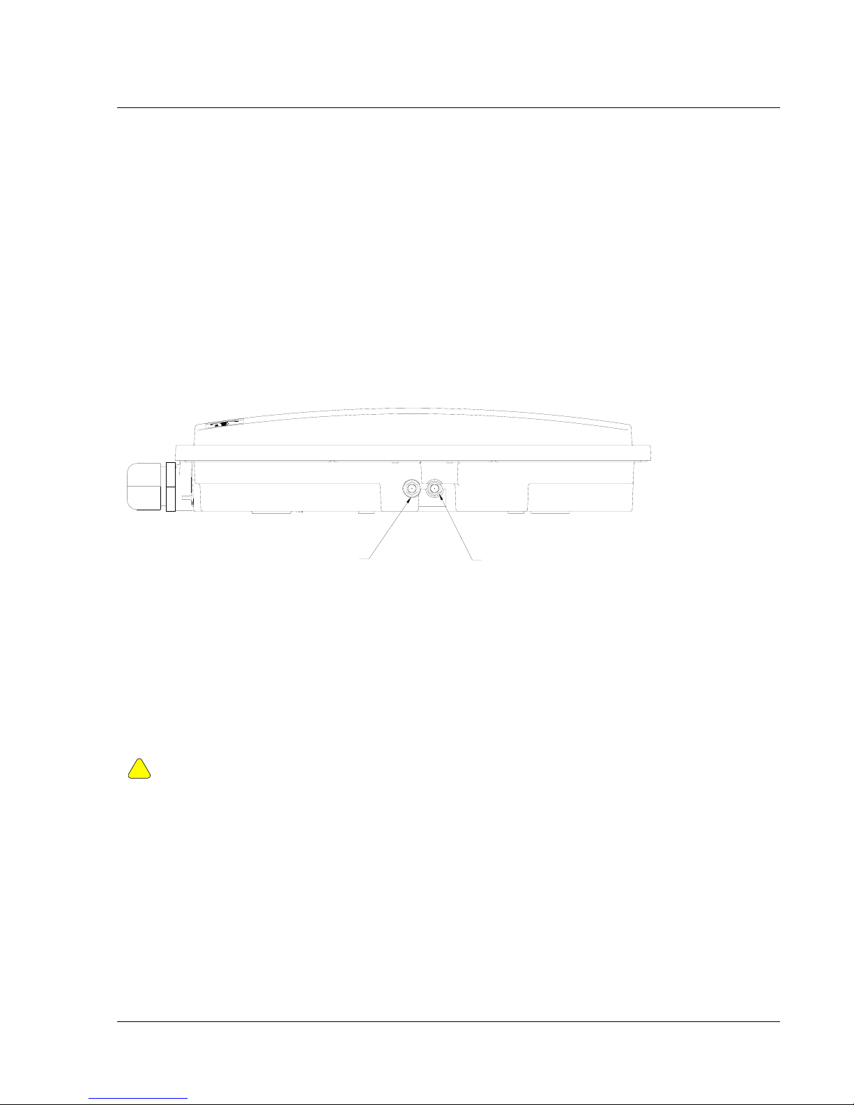
Antenna Connections
The radio is equipped with two reverse-polarity SMA connectors on the side for attachment to an external antenna.
Each SMA connector is labeled with either “V” for Vertical or “H” for Horizontal polarization.
VERTICAL
Connect each cable to the appropriate vertical and horizontal ports on both the antenna and the radio.
HORIZONTAL
Ethernet / Power Connections
See the TrangoLINK-10 User Manual for detailed diagram for connecting radio to network or PC utilizing the
power over Ethernet (PoE) J-Box and cat-5 cables.
IMPORTANT: DO NOT APPLY DC POWER TO THE RADIO UNTIL THE ANTENNA IS
!
ATTACHED OTHERWISE DAMAGE TO THE RADIO MAY OCCUR.
Setting the Maximum RF Power
The FCC allows a maximum EIRP of 1 watt (30 dBm) for devices transmitting in the 5.25 to 5.35 U-NII band. The
P5830S-MU-EXT and P5830S-RU-EXT’s factory default maximum power setting for this band is +6 dBm. If the
radio is to be equipped with Trango standard antennas AD5830-23-D or AD5830-24-D, no manual adjustment to
the max power setting is required since radio power output plus antenna gain does not exceed 30 dBm.
However, due to FCC restrictions the professional installer must manually reduce the maximum power for
the 5.25 to 5.35 GHz U-NII band if a higher gain antenna is to be used.
The table below shows the maximum power setting for the radio to achieve an EIRP of 1 watt (FCC limit). Only
the antennas listed below are FCC Certified for use with the TrangoLINK-10-EXT.
Trango Broadband Wireless – Rev. A
Page
3

RU Antenna Alignment
Antenna Model Antenna Gain (incl/cable loss) Radio Max power setting
AD5830-23-D +24 dBi +6 dBm
AD5830-24-D +24 dBi +6 dBm
SPD3-5.2 +30 dBi 0 dBm
TrangoLINK-10-EXT Professional Installation Guide
Note: that in all cases, Antenna Gain – cable loss + Radio Max Power Setting is 30 dBm. Once set, the power
leveling feature will still operate normally, but the maximum EIRP will never exceed 1 watt (30 dBm).
The Max Power Setting command is only accessible from the command line and is not available on the HTTP
Browser interface.
The telnet or serial port command to change the maximum power is:
uniimaxpower <max power in dBm>
The flash memory must be updated after running the command. save systemsetting
The command must be run prior to installing the antenna and while the Opmode is OFF.
Example: To set the max power setting for the AD5830-23-D:
#> uniimaxpower 6
#> save systemsetting
Note: The maximum RF power may be left at +22 dBm for the 5.725 to 5.85 GHz ISM band regardless of
which FCC Certified antenna is used. No manual setting is required.
Trango Broadband Wireless – Rev. A
Page
4
 Loading...