

Trango brodband Access5830 User Manual

Access5830™
Wireless Broadband System
USER MANUAL
[draft]

Access5830™ User Manual
Table of Contents
Overview 3
FCC Information 3
Warranty Information 3
Getting to Know Your Radio 4
Contents 4
Ethernet and Serial Ports 5
Antennas 5
AP/SU Operational Overview 5
Getting Started 7
Connections and Power 7
Basic Configuration 8
Opmode Concept 8
HTTP Browser Interface 9
Logging On to your Radio via Telnet. 9
Access Point Set Up and Configuration 10
AP System Information 10
AP Subscriber Unit Database 12
Subscriber Unit Set Up and Configuration 13
SU System Information 14
Establishing a Wireless Link 16
Access Point 16
Subscriber Unit 16
Association Concept (AP to SU communications) 16
Basic Diagnostics 17
Deployment 18
Site Selection 19
Site Survey 19
Channel Planning 19
Installation 20
SU Installation and Antenna Alignment 21
Link Test 22
Managing your Access5830 Network 22
Network Setup 22
Command Line Interface 22
Telnetting into remote SU 23
Managing AP from SU side of Network 23
Troublshooting 23
Specifications 24
Appendix 1 -- Access5830™ Command Line Interface (CLI) 25
Appendix 2 – HTTP Browser Interface 33
2

Access5830™ User Manual
Overview
This manual covers basic configuration and installation of the Access5830 Wireless Broadband System and
applies to the following radio part numbers:
M5830S-AP-60 Access Point with internal sectoral patch antenna
M5830S-SU Subscriber Unit with internal patch antenna
Note: The installation of the M5830S-SU requires professional installation due to FCC limits on output
power settings when using the 5.3 GHz U-NII band. Contact your sales person for more information
regarding the definition of “Professional Installation”.
FCC Information
This device complies with Part 15 of FCC Rules and Regulations. Operation is subject to the following two
conditions: (1) This device may not cause harmful interference and (2) this device must accept any
interference received, including interference that may cause undesired operation.
This equipment has been tested and found to comply with the limits for a Class B digital device, pursuant
to Part 15 of the FCC Rules. These limits are designed to provide reasonable protection against harmful
interference in a residential installation. This equipment generates, uses, and can radiate radio-frequency
energy and, if not installed and used in accordance with these instructions, may cause harmful interference
to radio communications. However, there is no guarantee that interference will not occur in any particular
installation. If this equipment does cause harmful interference to radio or television reception, which can be
determined by turning the equipment off and on, the user is encouraged to correct the interference by one of
more of the following measures:
1) Reorient the antenna;
2) Increase the separation between the affected equipment and the unit;
3) Connect the affected equipment to a power outlet on a different circuit from that which the receiver is
connected to;
4) Consult the dealer and/or experienced radio/TV technician for help.
FCC ID: NCYM5830SAP
FCC ID: NCYM5830SSU
Canada: XXXXXXXXXX
IMPORTANT NOTE:
Intentional or unintentional changes or modifications must not be made unless under the express consent of
the party responsible for compliance. Any such modifications could void the user’s authority to operate the
equipment and will void the manufacturer’s warranty. To comply with FCC RF exposure requirements, the
following antenna installation and device operating configurations must be satisfied. The antenna for this
unit must be fixed and mounted on outdoor permanent structures with a separation distance of at least two
meters from all persons. Furthermore, it must not be co-located or operating in conjunction with any other
antenna or transmitter.
Warranty Information
Radios from Trango Broadband Wireless are warranted from one year from date of purchase. Please see
www.trangobroadband.com
for complete description of warranty coverage and limitations
3
Access5830™ User Manual
Welcome!
Your Trango Broadband Access5830 radio system provides the latest innovations in high speed fixed
wireless broadband. The Access 5830 is a point-to-multipoint (PMP) system which provides network
connectivity at speeds up to 10 Mbps with a range of 10 miles or beyond depending on antenna
configuration. The Access5830 is unique in that it can operate in either the 5.8 GHz ISM band or the 5.3
GHz U-NII band.
The Access5830 system consists of two types of radios: Access Points (AP) and Subscriber Units (SU).
The AP will deliver wireless broadband service to one or more SU’s according to a proprietary polling
algorithm called SMARTPolling™. Each AP can associate with and deliver service to up to 512 SU’s.
With careful channel planning, (and adequate spacing and shielding) network operators can co-locate up to
22 AP’s at a single cell site.
The AP and SU conform to maximum radiated power limits as established by the FCC.
Band AP Max EIRP Approximate max range (AP to SU)
5.8 GHz ISM Band 36 dBm 6 Miles (allowing for 10 dB fade margin)
5.3 GHz U-NII Band 30 dBm 2 Miles (allowing for 10 dB fade margin)
In this document and within the radio configuration itself, the designators of “ISM” and “U-NII” are used
to distinguish between the two bands.
Getting to Know Your Radio
Contents
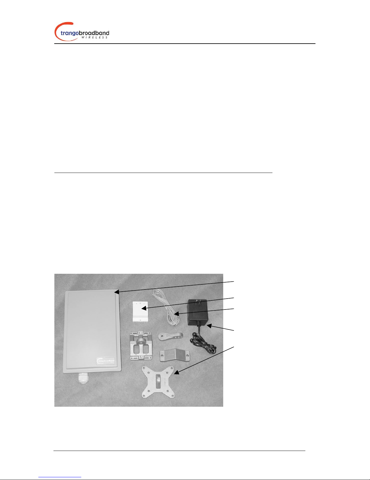
Each Access 5830 radio comes equipped with the radio itself, a power-over-Ethernet (POE) J-Box, an AC
adapter, and mounting hardware. The Access5830 AP (part # M5830S-AP-60) also comes with a serial
programming cable. Dual-polarized internal antennas are included within the radome of the AP and the
short range SU (Part #M5830S-SU).
Radio (AP or SU)
J Box (Power over Ethernet Injector)
Serial Programming Cable
(AP Only)
Power Supply (120 VAC – 20 VDC)
Mounting Hardware
4
Access5830™ User Manual
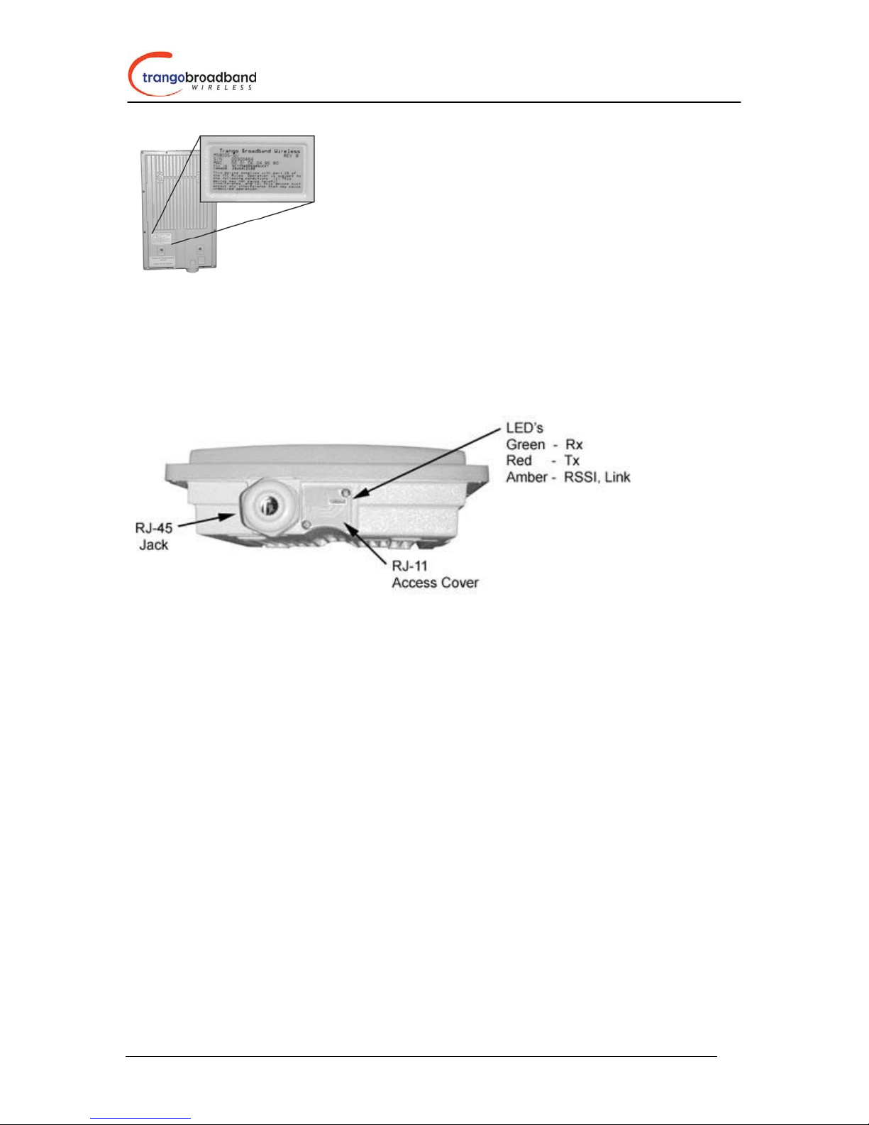
APs and SUs look identical. The only way to
tell them apart is by the model number printed
on the backside product label. This label also
contains the MAC ID of the radio as well as the
serial #.
Ethernet and Serial Ports
At the bottom of the Access5830 are two access ports: a twist-on weatherproof cable port for RJ-45
Ethernet (and POE), and an access cover (with two screws) for RJ-11 serial port. Most configuration and
management tasks can be performed through the Ethernet jack. The access cover also contains a small
window which reveals three LEDs. These LEDs provide RF link-status information and will be discussed
later in this text.
Antennas
The Access5830 AP and SU each include dual polarized patch antennas built in behind the plastic radome
cover. These antennas can be electronically switched between horizontal (H) or vertical (V) polarization.
AP/SU Operational Overview
The Access5830 AP is a sophisticated broadband wireless device that provides a host of comprehensive
tools and functions. The AP resides at the center of the point-to-multipoint (PMP) network and performs
all management functions including the allocation of bandwidth allocation for all associated SU’s. As
such, we refer to The Access5830 is an “AP-Centric” system.
One of the major advantages of the Access5830 system is the ability of the AP to handle multiple
SU connections and share the 10 Mbps data throughput very efficiently. Bandwidth allocation is
managed by the AP’s SMARTPolling algorithm according to provisioning rules set up by the
system administrator.
The AP unit acts as a hub in a star configuration wireless multipoint network supporting up to 512
subscriber units. The AP unit, hardwired to a network point of presence, polls each subscriber
unit SU in a round robin format to determine if the SU has data to transfer. The SU only transmits
the data “upstream” to the AP when the AP gives authorization via a “transmit grant”. The SU
parses every “downstream” data packet from the AP and identifies packets intended for it.
In order for an SU to communicate with an AP, the system administrator must first add the MAC
address and ID number of the SU to the user database in the AP.
5

Access5830™ User Manual
When power is first applied to a properly installed SU, it will scan all the channels in its scantable,
searching for an AP that is sending transmit grants for this particular SU. The SU will then stop
on that channel and respond to the AP using maximum RF power. Before the AP can add the SU
to the polling list, it must authenticate the SU by verifying the MAC address, and performing a
ranging operation to the SU. This process involves sending a special command to the SU and
getting an instantaneous reply from the SU.
Upon successfully locating and ranging the SU, The AP will then add the SU to the normal polling
list and level the RF transmit power level from the SU to set a good signal-to-noise ratio at the AP.
The AP uses several parameters to determine how often each SU is polled for data, and the
conditions of any data transfer, as follows:
1) Committed Information Rate (CIR)
2) Maximum Information Rate (MIR)
3) Priority
4) Poll response timeout
All the above parameters are set in the AP by the system administrator and cannot be controlled at
the SU. It should also be noted that the MAC table located in the AP is dynamic and stores up to
2000 entries. There is no limitation on the number of IP addresses or hardware devices that an
individual SU may have physically connected to it.
6
Access5830™ User Manual
Getting Started
First unpack your AP and at least one SU. It is recommended that novice users first provision and test the
radios on the bench before deploying in the field.
Connections and Power
Note: Connection and powering of radios is the same for AP’s and SU’s.
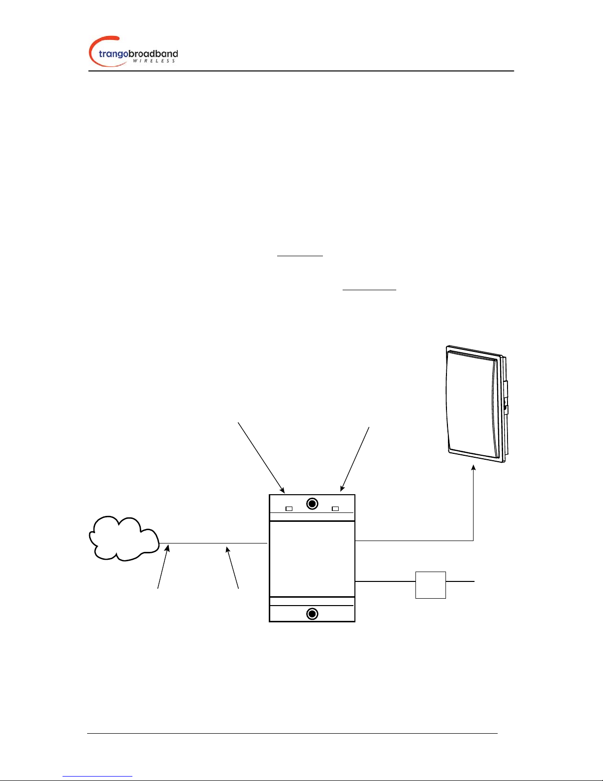
• Connect a Cat-5 (straight through) Ethernet cable (we recommend shielded twisted pair) between
the ODU (out door unit) port of the J-box and the RJ-45 connector on the radio. Note that this
cable will carry power over Ethernet (PoE). See appendix for PoE pinout diagram for this J-Box
to radio connection.
• If connecting to a COMPUTER, use a Cross-Over
to the computer’s Ethernet port.
If connecting to a HUB, SWITCH, or ROUTER, use a Straight-Thru
• Plug the AC adapter into an AC outlet.
Ethernet cable from the NET port of the J-box
cable.
AP or SU
Network
or
PC
Use straight-thru cable
if to hub, switch
or router
LED Indicates
power to J-Box
CAT-5
Use cross-over
cable if to PC
POWER ODU
ODUNET
POWER
Power over Ethernet
J-Box
LED Indicates
power to Radio
CAT-5
Straight-Thru
Cable
20 V
Power
Supply
AC Power
Both green LED’s on the J-box should be lit, indicating power is present at the J-box as well as the radio.
You are now ready to configure the radio via the Ethernet port.
7

Access5830™ User Manual
Note: If you cannot access the radio management functions via the Ethernet port, use the Serial
Programming cable (supplied with AP) and attach to RJ-11 located behind access cover on bottom of radio.
Basic Configuration
The Access5830 can be configured using either the Command Line Interface (CLI) or the Web Browser
(HTTP) interface. Although both methods are comprehensive and powerful, the CLI method provides
slightly more functionality. Regardless of which method is chosen, it is important to gain a good
understanding of the major CLI commands available. The entire CLI Command Set Reference is available
in a separate document. This user manual focuses on the CLI for radio configuration and management.
The CLI is accessible via telnet session (through Ethernet port) or via the serial port using Hyper-terminal.
If you would like to use the Hyperterminal via PC serial port, use settings 8-N-1 Flow control: None.
Opmode Concept
Before logging on to a radio, it is important to understand the “opmode” concept of the Access5830. AP’s
can be in one of two opmodes; “OFF” opmode, or “AP” opmode. When in “OFF” opmode the radio is not
radiating RF energy, and it is not attempting to associate with SU’s. “AP” opmode is the normal operating
mode of the AP which is used when radiating RF energy and associating with SU’s.
Similarly, SU’s have two opmodes: “SU” opmode or “OFF” opmode.
Opmode is important to understand for the following reason:
You can log onto an AP via Ethernet port (telnet or http browser) regardless of Opmode. However, you
can only log onto an SU (via the Ethernet port) when it is in Opmode “OFF”. Factory default opmode is
“SU”, however, while booting, the SU will wait 30 seconds before entering opmode “SU”. During this 30
second window, you can log onto the SU while it is in opmode “OFF”. Once you log onto the SU, the
progression to opmode “SU” will stop, and the unit will remain in opmode “OFF”. If accessing the SU via
the serial programming cable, you can log onto the unit weather it is in opmode “OFF” or opmode “SU”.
Also, certain commands, such as the site survey command (ssurvey) and the SU RSSI command (ssrssi)
can only be performed while the radio is in opmode “OFF”. See Appendix 1 Command Set Reference l for
a complete listing of commands, and the appropriate opmode(s) for each command.
8
Access5830™ User Manual
HTTP Browser Interface
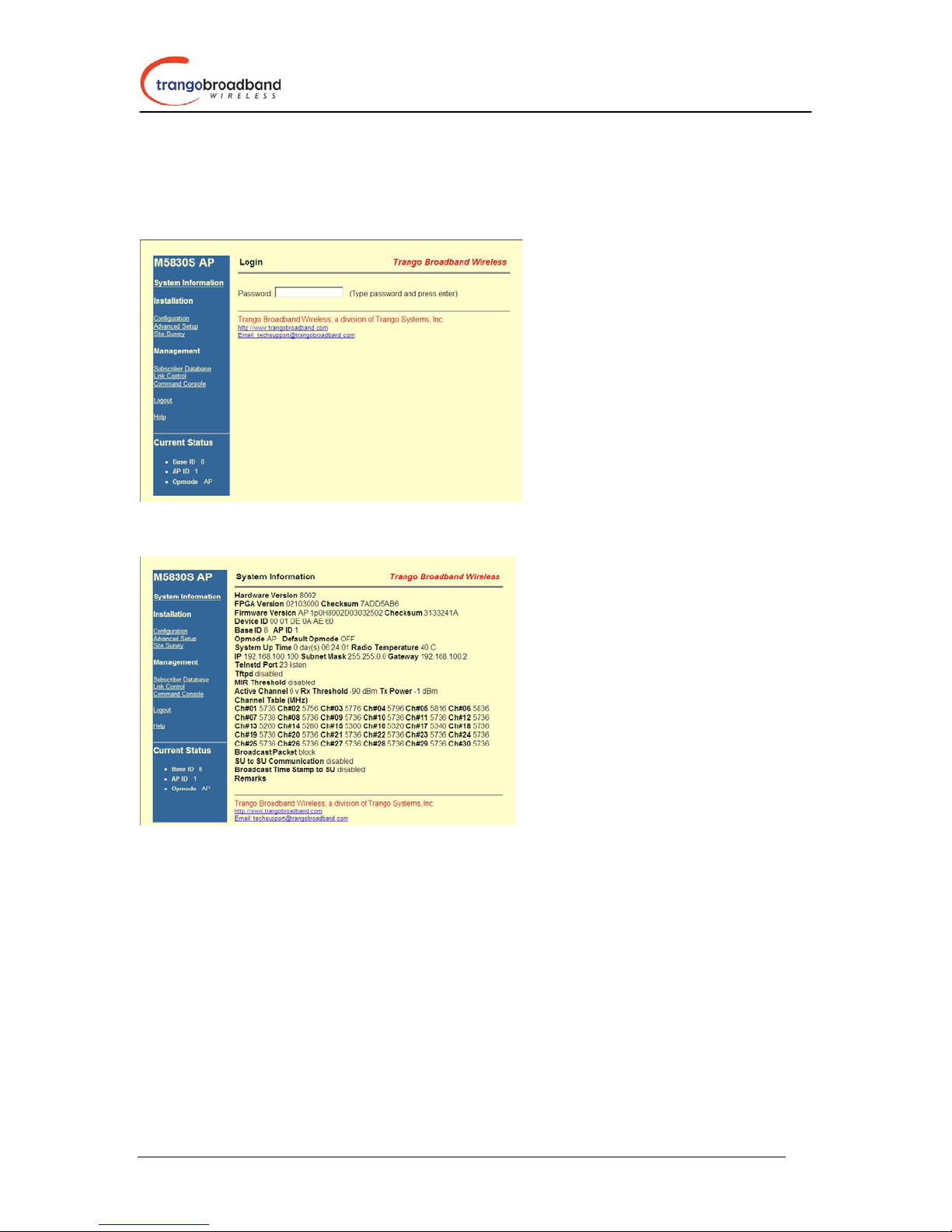
The HTTP browser interface is an easy-to-use configuration and management tool. In order to use the
browser interface – simply connect the radio to a PC, and type the radio’s IP address into the web browser
(i.e. Microsoft Internet Explorer). This will bring up a logon screen.
Type the password (default trango) and continue. This will bring up a screen similar to the following:
For more information on the HTTP browser interface, please see Appendix 3, or refer to the online
HELP button on the browser screen.
Logging On to your Radio via Telnet.
Open a command prompt (DOS) session on your PC. Open a Telnet session by typing
telnet [ip address of radio]
You will be greeted with current hardware and firmware information and prompted for a password. Type
in the password and press enter.
All Trango radios (AP and SU) come factory pre-configured with a default IP address
192.168.100.100. The default password is trango.
Prior to deployment you will want to change the password and assign a unique IP address to each radio.
9

Access5830™ User Manual
Access Point Set Up and Configuration
It is recommended to set up the AP prior to setting up the SU’s.
In the process of configuring the AP, you will:
1. Review and modify basic system information such as Base ID, RF Channel, etc.
2. Add SU’s to the Subscriber Unit Database (SUDB).
Logon to the AP and to receive a comprehensive snapshot of the system’s status, type the command
sysinfo. The result appear similar to:
Many of these parameters can be changed by the user. A description of each of these changeable
parameters, along with the related command is shown in the table below. Please note that in order to save
any changes to persistent storage, you must type the command: updateflash systemsetting. If you do not
update the flash, settings will be reset after reboot.
AP SYSINFO PARAMETERS AND RELATED COMMANDS
Parameter Description Related CLI Command
Device ID Mac ID of AP N/A
Base ID Specifies the cell or cluster that
the AP belongs to. Base ID is
one of three key pieces of
information, along with active
channel, and subscriber database
information for the link
establishment between the AP
and SU’s
10
set baseid <baseid>
 Loading...