

Trango Broadband TrangoLINK-45TM User Manual

Ffirm
TrangoLINK-45™
Point-to-Point
Wireless Ethernet Bridge
USER MANUAL
June, 2007
Revision 1p3

Preface
Table of Contents
Preface...................................................................................................................................................................iv
FCC Information.......................................................................................................iv
Industry Canada Information..................................................................................... v
Warranty Information ............................................................................................... v
Europe Information...................................................................................................vi
Chapter 1 Overview................................................................................................................................................8
DFS ......................................................................................................................... 8
OFDM ...................................................................................................................... 8
Adaptive Modulation ................................................................................................. 8
ARQ.........................................................................................................................9
Dual Polarity Antenna ............................................................................................... 9
Range vs. Throughput ............................................................................................ 10
System Contents .................................................................................................... 11
Location of Serial Number & MAC Address................................................................ 12
Location of RJ-45/LED Port & IP Reset Button .......................................................... 12
Chapter 2 Getting Started .....................................................................................................................................13
Connections and Power........................................................................................... 13
Configuration Tools................................................................................................. 14
Changing Password ................................................................................................ 14
Troubleshooting Ethernet Connections..................................................................... 15
System Information (sysinfo) Page .......................................................................... 15
Chapter 3 Configuration .......................................................................................................................................20
Key Concepts ......................................................................................................... 20
Essentials to Establish a Wireless Link...................................................................... 20
Master Unit Configuration........................................................................................ 20
Remote Unit Configuration ...................................................................................... 21
Establishing a Wireless Link..................................................................................... 22
Changing IP Address............................................................................................... 22
LEDs...................................................................................................................... 22
RF Link Loopback Test (linktest command)............................................................... 23
Link Speed & Power Settings................................................................................... 25
MU Autoscan Feature Description ............................................................................ 26
Automatic Rate Shifting Feature Description............................................................. 27
Encryption Feature Description................................................................................ 28
MIR Feature Description.......................................................................................... 28
Command Reference Listing.................................................................................... 29
Chapter 4 Deployment & Installation...................................................................................................................32
Site Selection ......................................................................................................... 32
Site survey............................................................................................................. 32
Channel Planning.................................................................................................... 33
RSSI Command and Antenna Alignment................................................................... 34
Setting Maximum RF Power for Legal Operation in the U-NII Bands (-EXT only)......... 34
Mounting Hardware ................................................................................................ 35
Connecting External Antenna on EXT Model ............................................................. 36
Weatherizing.......................................................................................................... 36
Grounding.............................................................................................................. 37
Cat-5 Cabling Considerations................................................................................... 37
Chapter 5 SNMP ..................................................................................................................................................38
SNMP..................................................................................................................... 38
Trango Broadband Wireless TrangoLINK-45 page ii

Table of Figures Trango
Chapter 6 Firmware Upgrade Procedure..............................................................................................................39
Firmware File Names .............................................................................................. 39
Firmware Upgrade Password................................................................................... 39
Upgrade Procedure................................................................................................. 39
Example 1 Upgrade main image firmware to 1.0a6.................................................. 39
Appendix A Using the HTTP Interface.........................................................................................................41
Configuration Screen – Minimum Required Settings to Establish a Wireless Link......... 45
Appendix B Specifications............................................................................................................................49
RF Parameters........................................................................................................ 49
Channels of Operation ............................................................................................ 50
Data Parameters..................................................................................................... 52
Regulatory Compliance ........................................................................................... 52
Mechanical............................................................................................................. 53
Environmental........................................................................................................ 53
Power Parameters .................................................................................................. 53
Power Supply ......................................................................................................... 53
Antennas................................................................................................................ 54
Trango Broadband Wireless — TrangoLINK-45 page iii

Preface
Preface
This manual covers the basic configuration and installation of the TrangoLINK-45 Wireless Point to Point Broadband
System, and applies to the following radio part numbers:
P5055M-19-xx Radio unit with internal 19 dBi patch antenna array
P5055M-23-xx Radio unit with internal 23 dBi patch antenna array
P5055M-EXT-xx Radio unit with external RP-SMA antenna connectors
Where “xx” denotes the regulatory configuration of the unit as follows:
US: For use in the USA
IC: For use in Canada
EU: For use in the following EU member and non-member countries:
Austria, Belgium, Cyprus, Czech Republic, Denmark, Estonia, Finland, France, Germany, Greece, Hungary, Iceland (Non
Members), Ireland, Italy, Latvia, Lithuania, Luxembourg, Malta, Norway (Non Members), Poland, Portugal, Slovak Republic,
Slovenia, Spain, Sweden, Netherlands, United Kingdom, Switzerland (Non Members),Bulgaria, Romania
OE: OEM model for individual certification in other countries
Each radio unit is supplied with the proper mounting hardware, a power adapter, and POE box with LED indicators.
Cables must be supplied by the installer.
Two radio units are required to make a TrangoLINK-45 link. The P5055M-EXT-xx must be used in conjunction with an
approved external antenna (sold separately). Instead of an internal antenna, the P5055M-EXT-xx has two reverse polarity
SMA RF Connectors for the attachment of external antenna cables.
FCC Information
FCC ID: NCYP5055M
The TrangoLINK-45 System is used for point-to-point operation only.
NOTE: The P5055M-EXT-xx requires professional installation due to FCC limits on output power settings when
operating in the UNII band.
This device complies with Part 15 of the FCC Rules and Regulations. Operation is subject to the following two
conditions: (1) This device may not cause harmful interference, and (2) this device must accept any interference received,
including interference that may cause undesired operation.
This equipment has been tested and found to comply with the limits for a Class B digital device, pursuant to Part 15 of the
FCC Rules. These limits are designed to provide reasonable protection against harmful interference in a residential
installation. This equipment generates, uses, and can radiate radio-frequency energy and, if not installed and used in
accordance with these instructions, may cause harmful interference to radio communications. However, there is no
guarantee that interference will not occur in any particular installation. If this equipment does cause harmful interference
to radio or television reception, which can be determined by turning the equipment off and on, the user is encouraged to
correct the interference by one of more of the following measures:
1) Reorient the antenna.
2) Increase the separation between the affected equipment and the unit.
3) Connect the affected equipment to a power outlet on a different circuit from that which the receiver is connected to.
4) Consult the dealer and/or experienced radio/TV technician for help.
Trango Broadband Wireless — TrangoLINK-45 page iv

Preface Industry Canada InformationIndustry Canada InformationIndustry
Canada Information
WARNING:
Intentional or unintentional changes or modifications must not be made unless under the express consent of the party
responsible for compliance. Any such modifications could void the user’s authority to operate the equipment and will
void the manufacturer’s warranty. To comply with RF exposure requirements, the following antenna installation and
device operating configurations must be satisfied. The antenna for this unit must be fixed and mounted on outdoor
permanent structures with a separation distance of at least two meters from all persons. Furthermore, it must not be colocated or operating in conjunction with any other antenna or transmitter.
Industry Canada Information
IC: 2945A-P5055M
Information for P5055M-EXT-IC
This device has been designed to operate with the antennas listed below, and having a maximum gain of 34 dBi.
Antennas not included in this list or having a gain greater than 34 dBi are strictly prohibited for use with this
device. The required antenna impedance is 50 ohms.
Approved Antennas:
Radiowaves model : SPD4-5.2
Radiowaves model : SPD3-5.2
Radiowaves model : SPD2-5.2
Radiowaves model : SPD1-5.2
To reduce potential radio interference to other users, the antenna type and its gain should be so chosen that the
equivalent isotropically radiated power (e.i.r.p.) is not more than that permitted for successful communication.
Warranty Information
Radios from Trango Broadband Wireless are warranted for one year from date of purchase. Please see
www.trangobroadband.com
for a complete description of warranty coverage and limitations.
Trango Broadband Wireless — TrangoLINK-45 page v

Preface Europe InformationEurope InformationEurope Information
Europe Information
We, Trango Systems, Inc.,
15070 Avenue of Science
Ste 200
San Diego, California, 92128 USA
Tel +1 858 653 3900
Fax +1 858 621 2725
Hereby declare that the product(s) listed below,
Product Name: Wireless Ethernet point to point radio with 19 dBi antenna
Model No: P5055M-19-EU
Product Name: Wireless Ethernet point to point radio with 23 dBi antenna
Model No: P5055M-23-EU
Product Name: Wireless Ethernet point to point radio with connectors
Model No: P5055M-EXT-EU
To which this declaration relates, are in conformity with the following standards and/or other normative documents:
EN 301 893 v1.3.1 (2005-08)
EN 301 489-17 v1.2.1 (2002-08)
EN 60950-1/IEC 60950-1:2001 First Edition
EN 50385: 2002
We hereby declare that all essential radio test suites have been carried out and that the above named products are in
conformity with all the essential requirements of Directive 1999/5/EC.
The conformity assessment procedure referred to in Article 10(5) and detailed in Annex IV of Directive 1999/5/EC
has been followed with the involvement of the following Notified Body:
Compliance Certification Services (ID#0984)
47173 Benicia St.
Fremont, CA 94538 USA
The –EU models will have the following label attached to them on the back of the individual radio unit and on the
packing box:
Trango Broadband Wireless — TrangoLINK-45 page vi

Preface Europe InformationEurope InformationEurope Information
Contact Information
Corporate Headquarters Trango Broadband Wireless, a division of Trango Systems, Inc.
15070 Avenue of Science Suite 200
San Diego, CA 92128 USA
Web Sites www.trangobroadband.com www.trangosys.com
Sales Inquiries email: sales@trangobroadband.com
Telephone: 1-858-653-3900
Technical Support email: techsupport@trangobroadband.com
Telephone: 1-858-653-3900
Firmware Update Notices Mailing List http://www.trangobroadband.com/mailinglist/mailingListAdd.aspx
Trango Broadband Wireless — TrangoLINK-45 page vii

Overview DFS
Chapter 1 Overview
The TrangoLINK-45 is a point-to-point (PtP) wireless Ethernet transmission system which provides network
connectivity at speeds up to 45 Mbps depending on the transmission distance and noise floor. The TrangoLINK-45
utilizes OFDM technology and is designed for use in long range backhaul and wide area data networking applications.
Users are required to simply specify one P5055M unit type as master unit (MU) and one unit as remote unit (RU) to
establish a link. Each unit utilizes power-over-Ethernet (PoE) and is designed for outdoor environments. The cable
entry point can accommodate both Shielded twisted pair Cat5 (STP) and unshielded twisted pair Cat5 (UTP), with the
addition of conduit for tower mounting.
DFS
One of the key features of the TrangoLINK-45 is that it has Dynamic Frequency Selection (DFS) which allows it to be
operated in the 5.25 to 5.35 GHz and 5.47 to 5.7 GHz frequency ranges depending upon the regulatory requirements.
When operating in these frequencies ranges the MU will monitor the channel for radar transmissions and switch to a new
channel automatically if radar is detected. The RU will switch to the new channel as well and the link will be
automatically reconnected, typically in about 1 minute.
Each radio unit has a different threshold for detecting radar that corresponds to the radio’s antenna gain. For the
P5055M-19-xx models, the threshold is –46 dBm. Any radar signal arriving at the antenna on the operating channel that
has an amplitude greater than –46 dBm will cause the MU and it’s associated RU to switch to a randomly selected
channel that is tagged as a DFS channel in the channel table. For the P5055M-23-xx units, the threshold is is –42 dBm,
and for the P5055M-EXT-xx units the threshold is –37 dBm.
IMPORTANT NOTE: When operating in the DFS frequencies, the radio units will use automatic transmit power
control (ATPC) to maintain the RSSI at a level of approximately –62 dBm. For very short link distances it may not be
possible for the transmit power to be reduced below the Radar detection threshold and the radio may not be able to
establish a reliable link. Trango recommends that careful link budget planning be done to ensure that this
condition does not exist.
OFDM
The TrangoLINK-45 platform utilizes Orthogonal Frequency Division Duplex (OFDM) processing which offers link
stability and performance in the presence of multipath interference.
Adaptive Modulation
One of the key advantages of the TrangoLINK-45 series radio platform is utilization of multiple modulation schemes
including the following:
• Binary Phase Shift Keying (BPSK)
• Quadrature Phase Shift Keying (QPSK)
• 16 Quadrature Amplitude Modulation (16QAM)
• 64 Quadrature Amplitude Modulation (64QAM)
The TrangoLINK-45 system allows individual selection of the upstream and downstream modulation schemes. The
modulation schemes can be adjusted manually or automatically (automatic rate shifting) for changing propagation and
interference conditions. The higher order modulation schemes (64QAM) are typically deployed at reduced ranges while
lower order modulation schemes (BPSK) are implemented at long distances.
Trango Broadband Wireless — TrangoLINK-45 page 8

Overview ARQ
ARQ
Another key advantage of the TrangoLINK-45 platform is its Automatic Repeat Request (ARQ) transmission correction
scheme. The ARQ algorithm detects packet loss due to fading and interference conditions and requests the remote radio
to re-transmit specific packets.
Dual Polarity Antenna
TrangoLINK-45 radios feature built-in dual polarity antenna functionality. Users may select either horizontal or
vertical antenna polarity through the unit’s software. The feature of selecting antenna polarity provides greater spectral
flexibility and ability to mitigate interference.
Trango Broadband Wireless — TrangoLINK-45 page 9

Overview Range vs. Throughput
Range vs. Throughput
The following table shows approximate maximum ranges (at recommended fade margins) achievable with the
TrangoLINK-45 system using various antenna configurations. Longer ranges are achievable, but will result in lower fade
margins. To estimate theoretical throughput and fade margin for any distance, download the link budget / fade margin
calculator tool from www.trangobroadband.com
ISM (5725 MHz to 5875 MHz) Line-of-Sight Range & Throughput
Antenna 5 miles 20 miles 30 miles
.
Integrated 23 dBi
15” Flat Panel
External 27 dBi
2’ Dish
External 30 dBi
3’ Dish
External 34 dBi
4’ Dish
45 Mbps
(10 db fade margin)
45 Mbps
(18 db fade margin)
45 Mbps
(24 db fade margin)
45 Mbps
(30 db fade margin)
11 Mbps
(14 db fade margin)
20 Mbps
(18 db fade margin)
26 Mbps
(20 db fade margin)
32 Mbps
(20 db fade margin)
6 Mbps
(17 db fade margin)
10 Mbps
(20 db fade margin)
18 Mbps
(22 db fade margin)
30 Mbps
(15 db fade margin)
U-NII (5470 MHz to 5725 MHz & 5250 MHz to 5350 MHz) Line-of-Sight Range & Throughput
Antenna 6 miles 10 miles 15 miles
Integrated 23 dBi
15” Flat Panel
External 27 dBi
2’ Dish
External 30 dBi
3’ Dish
20 Mbps
(10 db fade margin)
31 Mbps
(11 db fade margin)
31 Mbps
(14 db fade margin)
11Mbps
(12 db fade margin)
20 Mbps
(10 db fade margin)
20 Mbps
(13 db fade margin)
6Mbps
(9 db fade margin)
11Mbps
(12 db fade margin)
16Mbps
(12 db fade margin)
External 34 dBi
4’ Dish
45 Mbps
(10 db fade margin)
30 Mbps
(13 db fade margin)
20Mbps
(14 db fade margin)
Trango Broadband Wireless — TrangoLINK-45 page 10
Overview System Contents
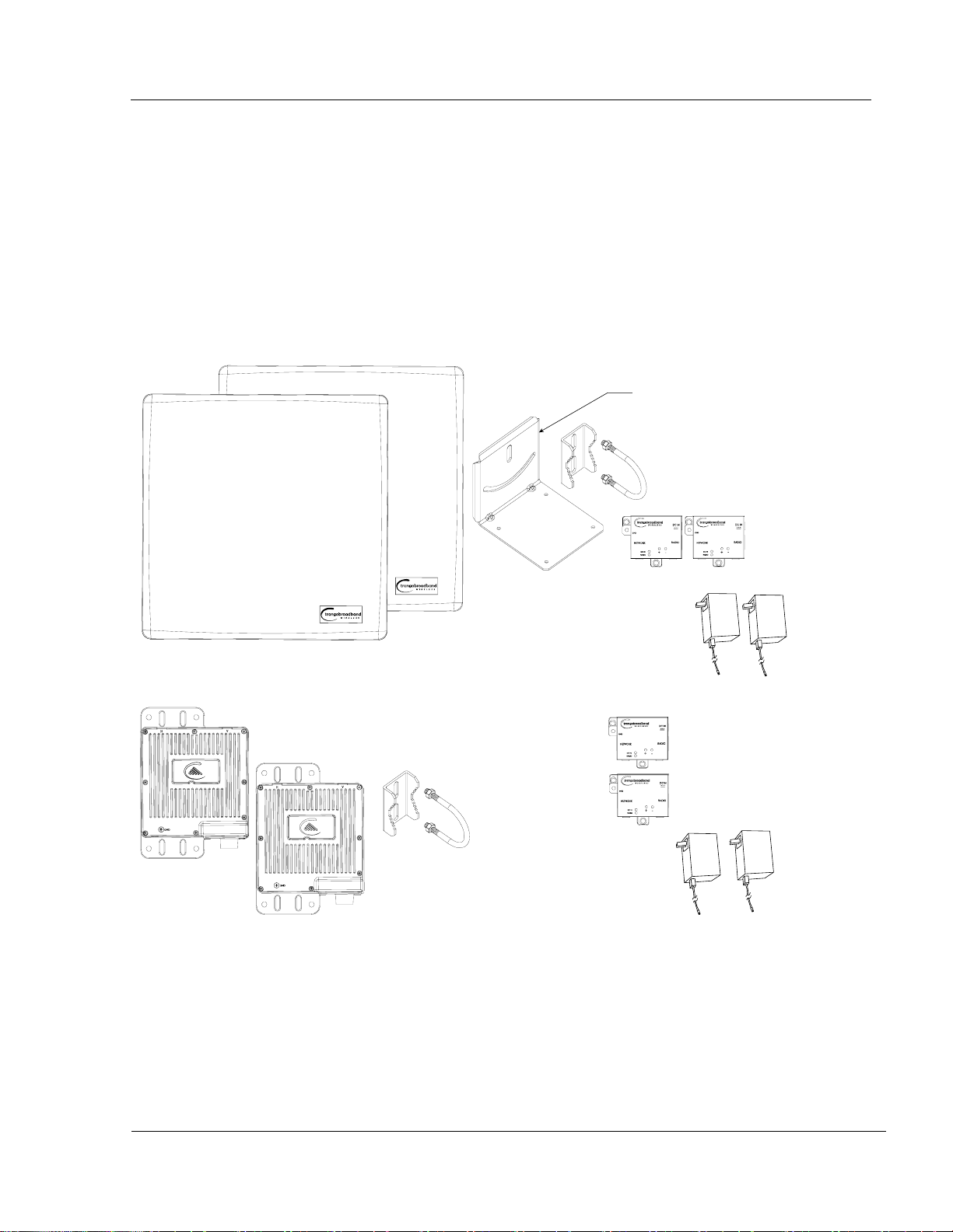
System Contents
The TrangoLINK-45 system is available in two versions:
TrangoLINK-45-19-xx - Radios with integrated 19 dBi antennas (part numbers P5055M-19-xx)
TrangoLINK-45-23-xx - Radios with integrated 23 dBi antennas (part numbers P5055M-23-xx)
TrangoLINK-45-EXT-xx - Connectorized radios (part numbers P5055M-EXT-xx)
Each TrangoLINK-45 kit consists of two radios, two power-over-Ethernet (PoE) injectors, two AC adapters, port covers,
and mounting hardware. A dual-polarized integrated antenna is located behind the radome of the P5055M-19-xx and
P5055M–23-xx units.
Trango Broadband Wireless — TrangoLINK-45 page 11
Overview Location of Serial Number & MAC Address
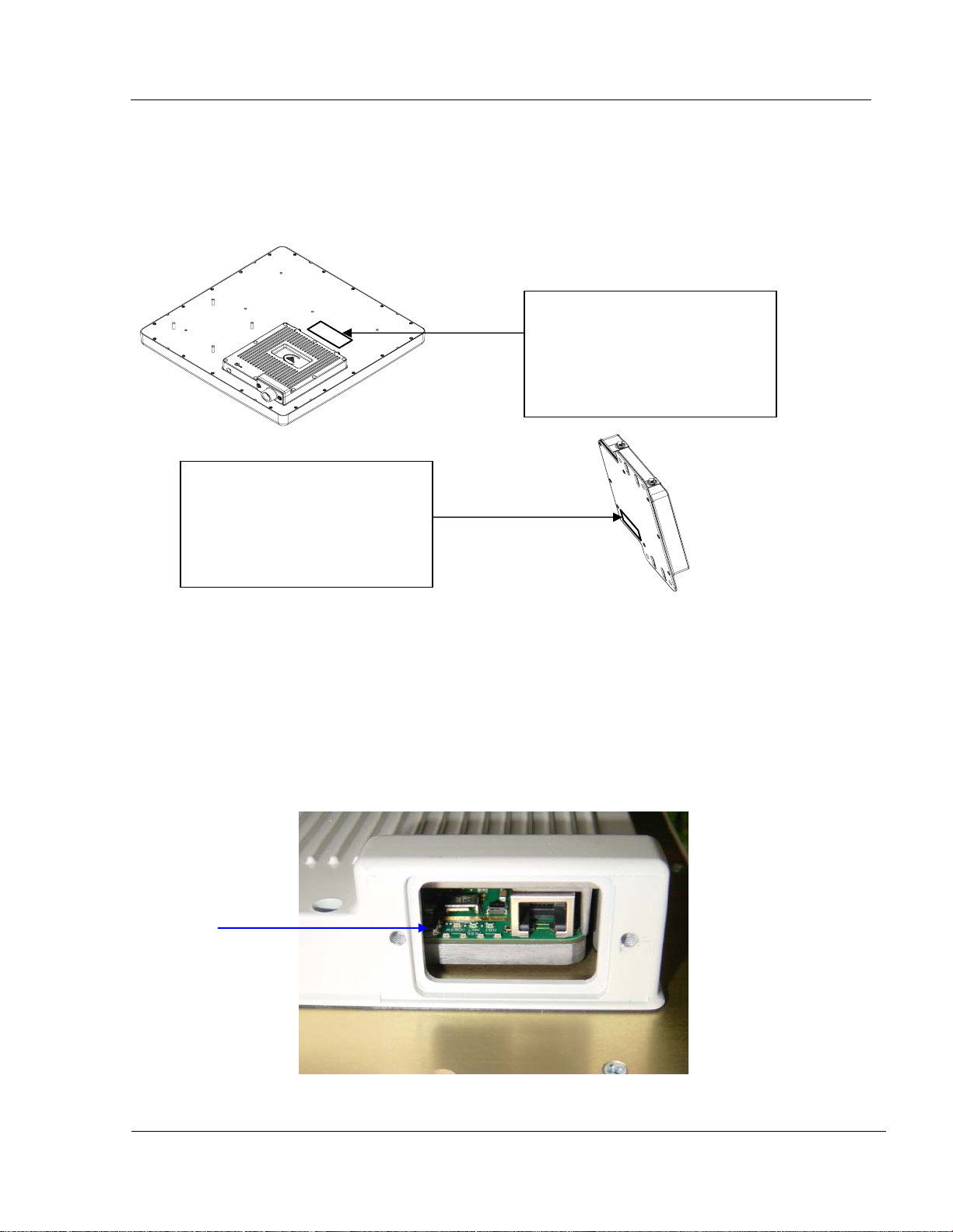
Location of Serial Number & MAC Address
The serial number and MAC address label can be found on the back of each radio. The serial number and MAC address
is also provided within the system information (sysinfo) screen.
Trango Broadband Wireless
P5055M- 23-US Rev. A
S/N: 000001420
MAC: 00 01 DE 00 02 F2
FCC ID: NCYP5055M
Canada: 2945AP5055M
THIS DEVICE COMPLIES WITH PART 15 OF THE FCC RULES: OPERATION IS
SUBJECT TO THE FOLLOWING CONDITIONS: (1) THIS DEVICE MAY NOT
CAUSE HARMFUL INTERFERANCE, AND (2) THIS DEVICE MUST ACCEPT
ANY INTERFERENCE THAT MAY CAUSE UNDESI RED OPERATION.
P5055M-23-US
Trango Broadband Wireless
P5055M- EXT-US Rev. A
S/N: 000001421
MAC: 00 01 DE 00 02 F3
FCC ID: NCYP5055M
Canada: 2945AP5055M
THIS DEVICE COMPLIES WITH PART 15 OF THE FCC RULES: OPERATION IS
SUBJECT TO THE FOLLOWING CONDITIONS: (1) THIS DEVICE MAY NOT
CAUSE HARMFUL INTERFERANCE, AND (2) THIS DEVICE MUST ACCEPT
ANY INTERFERENCE THAT MAY CAUSE UNDESIRED OPERATION.
P5055M-EXT-US
Location of RJ-45/LED Port & IP Reset Button
The RJ-45 connector, diagnostic LEDs, and reset button are located at the bottom of the radio. Functionality of the
LEDs is described later in this text. The IP reset button resets IP configuration and password back to factory default.
The reset button does not reset any other parameters other than IP configuration and password. Typically a user would
only press the reset button when the IP configuration or password in unknown. Reset button must be held down for
approximately 10 seconds.
IP Reset Button
Trango Broadband Wireless — TrangoLINK-45 page 12
Getting Started Connections and Power
Chapter 2 Getting Started
It is always a good idea to first provision and test the radios on the bench before deploying them in the field. This is a
particularly useful exercise for the novice user.
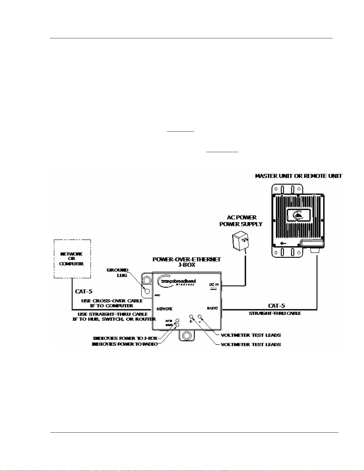
Connections and Power
• Connect a Cat-5 (straight through) Ethernet cable (we recommend shielded twisted pair) between the ODU (out
door unit) port of the J-box and the RJ-45 connector on the radio. Note that this cable will carry power-overEthernet (PoE).
• If connecting to a COMPUTER, use a Cross-Over
computer’s Ethernet port.
If connecting to a HUB, SWITCH, or ROUTER, use a Straight-Thru
• Plug the AC adapter into an AC outlet.
Ethernet cable from the NET port of the J-box to the
cable.
Both green LEDs on the J-box should be lit, indicating power is present at the Power-over-Ethernet box as well as at the
radio.
You are now ready to configure the radio via the Ethernet port. After reboot, the Radio Power LED may take several
seconds before lighting. The radio requires approximately 45 seconds to boot.
Trango Broadband Wireless — TrangoLINK-45 page 13

Getting Started Configuration Tools
Configuration Tools
P5055M radios can be configured using either the Command Line Interface (CLI), or the Web Browser (HTTP)
interface. The CLI method provides slightly more functionality.
This text covers configuration through the CLI. For HTTP configuration please see Appendix A.
Telnet
Open a command prompt (DOS) session on your PC. Open a Telnet session by typing:
telnet <ip address of radio>
Example:
C:>telnet 192.168.100.100
Note: All Trango radios are pre-configured at the factory with a default IP address of 192.168.100.100.
You will be greeted with current hardware and firmware information and prompted for a password. Type in the
password and press enter. The factory default read/write password is trango.
Welcome to Trango Broadband Wireless, TrangoLINK-45 DFS PtP-P5055M
2p0r1D07061104
Password:
Login as read/write.
#>
Note: Type help for a listing of all CLI commands. Type help [<command>], for the syntax of a particular
command.
Note: If you cannot access the radio management functions via the Ethernet port, check all cable connections and
ensure that your PC is set up with a properly routable subnet.
Changing Password
Three types of passwords are used in the TrangoLINK-45 system:
rw read write password. User can view and update all system parameters
ro read only password. User can view system information only
Upgrade Firmware upgrade password. This password must be included in the file name of the main
image and web browser firmware files during the TFTP upload process.
Use the password <ro|rw|upgrade>command to change the various passwords.
Examples:
#> password rw
New Password (4 to 16 characters): *******
Confirm Password: *******
Success.
#> password ro
New Password (4 to 16 characters): ******
Confirm Password: ******
Success.
Trango Broadband Wireless — TrangoLINK-45 page 14

Getting Started Troubleshooting Ethernet Connections
Troubleshooting Ethernet Connections
If you cannot telnet into the radio or open an HTTP browser session, check your cable connections to ensure proper use
of cross-over vs. straight-through cable, and ensure your PC’s subnet is routable to the radio’s IP address.
System Information (sysinfo) Page
To display system configuration and status information type the command sysinfo.
The sysinfo screen is divided into 7 sections (0 –7)
Section Description
0 Hardware/Firmware versions & system uptime (since reboot)
1 Mac, serial number, and IP configuration information
2 Opmode, RF info, speed, and peer connection status
3 RF channel table
4 Area code information denotes which channels and power limits are available based on region
code of the radio. Area code is set by the factory and can not be altered by the user.
5 ARQ status, encryption, Auto-rate shift, remarks, and LED RSSI function
6 Ethernet TX/RX statistics.
Trango Broadband Wireless — TrangoLINK-45 page 15

Getting Started System Information (sysinfo) Page
Sysinfo Example:
#> sysinfo
********************************* 0 *********************************
[Model] P5055M
[Area Code] 0
[Unit Type] RU
[Hardware Version] 5055
[Firmware Version] 2p0r1D07061104
[System Up Time] 7 day(s) 03:58:16
********************************* 1 *********************************
[MAC] 00 01 DE 61 59 F7
[S/N] 6380023
[IP] 10.8.2.149 [Subnet Mask] 255.255.255.224 [Gateway] 10.8.2.129
********************************* 2 *********************************
[Radio Temp] 34 C [PoE Voltage] 14.2 V
[Opmode] on [Default Opmode] on
[Active Channel] 22 h [Freq] 5840 MHz
[Speed] 6 Mbps [Tx Power] 0 dBm [Power Range] -10..22 dBm
[Peer ID] DE6159FA [Status] disconnect [RSSI] n/a
[Peer IP Config] n/a
[DFS Status] idle
********************************* 3 *********************************
Channel Table: (MHz, n/a: not available in current area)
[Ch#01] 5265 dfs [Ch#02] 5285 dfs [Ch#03] 5305 dfs [Ch#04] 5325 dfs
[Ch#05] 5500 dfs [Ch#06] 5520 dfs [Ch#07] 5540 dfs [Ch#08] 5560 dfs
[Ch#09] 5580 dfs [Ch#10] 5600 dfs [Ch#11] 5620 dfs [Ch#12] 5640 dfs
[Ch#13] 5660 dfs [Ch#14] 5680 dfs [Ch#15] 5700 dfs [Ch#16] 5735
[Ch#17] 5755 [Ch#18] 5775 [Ch#19] 5795 [Ch#20] 5815
[Ch#21] 5835 [Ch#22] 5840 [Ch#23] 5840 [Ch#24] 5840
Default Channel Table:
[Ch#01] 5265 dfs [Ch#02] 5285 dfs [Ch#03] 5305 dfs [Ch#04] 5325 dfs
[Ch#05] 5500 dfs [Ch#06] 5520 dfs [Ch#07] 5540 dfs [Ch#08] 5560 dfs
[Ch#09] 5580 dfs [Ch#10] 5600 dfs [Ch#11] 5620 dfs [Ch#12] 5640 dfs
[Ch#13] 5660 dfs [Ch#14] 5680 dfs [Ch#15] 5700 dfs [Ch#16] 5735
[Ch#17] 5755 [Ch#18] 5775 [Ch#19] 5795 [Ch#20] 5815
[Ch#21] 5835 [Ch#22] 5840 [Ch#23] 5840 [Ch#24] 5840
********************************* 4 *********************************
[Area Code] 0
RF Band #1 (5180..5260 MHz) Disabled
RF Band #2 (5265..5325 MHz) [Power Range] -10..10/10/10/10 dBm
RF Band #3 (5500..5700 MHz) [Power Range] -10..10/10/10/10 dBm
RF Band #4 (5735..5840 MHz) [Power Range] -10..22/21/19/17 dBm
Trango Broadband Wireless — TrangoLINK-45 page 16

Getting Started System Information (sysinfo) Page
********************************* 5 *********************************
[Tx MIR] 50000 Kbps
[ARQ] on
[Encrypt] off [Key] 0011 2233 4455 6677 8899 AABB CCDD EEFF
[Auto Rate Shift] on
[Auto Scan MU] off
[RSSI LED] on
[Remarks] Remarks
********************************* 6 *********************************
[Eth Config] ANEG
[Eth Status] 100 FDX
[Eth In] 35,262,413 bytes 3 Kbps
[Eth Out] 9,201,047 bytes 51 Kbps
[RF In] 0 bytes 0 Kbps
[RF Out] 0 bytes 0 Kbps
[ARQ Retransmission] 0 pkts
Success.
#>
To view only a particular section of the sysinfo screen, type sysinfo followed by the desired section number.
Example:
#> sysinfo 2
********************************* 2 *********************************
[Radio Temp] 34 C [PoE Voltage] 14.2 V
[Opmode] on [Default Opmode] on
[Active Channel] 22 h [Freq] 5840 MHz
[Speed] 6 Mbps [Tx Power] 0 dBm [Power Range] -10..22 dBm
[Peer ID] DE6159FA [Status] disconnect [RSSI] n/a
[Peer IP Config] n/a
[DFS Status] idle
Success.
#>
Each of the parameters within the sysinfo screen is defined below
Section 0
[Model] Radio Model # (P5055M)
[Unit Type] User defined Unit Type (MU or RU)
[Hardware Version] Hardware version set by factory (5010)
[Firmware Version] Current firmware version loaded in radio
[System Up Time] Time since last reboot or power cycle
Section 1
[MAC] MAC address of radio
Trango Broadband Wireless — TrangoLINK-45 page 17
 Loading...