

Trango Broadband TrangoLink-10 User Manual

TrangoLINK-10
Point to Point
Wireless Ethernet Bridge
USER MANUAL
June, 2007
Revision E 3.0

Table of Contents Trango
Table of Contents
Table of Contents .................................................................................................................................................. ii
Preface...................................................................................................................................................................iv
FCC Information .......................................................................................................iv
Warranty Information ...............................................................................................iv
Chapter 1 Overview................................................................................................................................................1
Contents .................................................................................................................. 1
Ethernet and Serial Ports.......................................................................................... 2
Operational Overview............................................................................................... 2
Chapter 2 Getting Started .......................................................................................................................................3
Connections and Power ............................................................................................ 3
Basic Configuration - Concepts and Tools .................................................................. 4
Opmode Concept...................................................................................................... 4
Browser Interface..................................................................................................... 4
Command Line Interface........................................................................................... 6
Troubleshooting ....................................................................................................... 6
Serial Port................................................................................................................ 7
Changing Password .................................................................................................. 7
Chapter 3 Configuration .........................................................................................................................................8
Essentials to Establish a Wireless Link ........................................................................ 8
Master Unit Configuration.......................................................................................... 8
Settings ................................................................................................................... 9
Master Unit Configuration Screen............................................................................... 9
Remote Unit Configuration Screen .......................................................................... 10
Basic Diagnostics .................................................................................................... 11
Master Unit’s System Information ............................................................................ 12
Remote Unit System Information ............................................................................ 15
Chapter 4 Deployment & Installation...................................................................................................................17
Site Selection......................................................................................................... 17
Site survey ............................................................................................................. 17
Channel Planning ................................................................................................... 18
Installation ............................................................................................................ 18
Mounting Hardware ................................................................................................ 18
Cabling and Weather Considerations ....................................................................... 20
Weatherizing.......................................................................................................... 21
RU Installation and Antenna Alignment ................................................................... 21
RU Antenna Alignment Procedure ........................................................................... 21
Chapter 5 Management.........................................................................................................................................23
RU Management ..................................................................................................... 23
SNMP ..................................................................................................................... 23
Objects for Monitoring and Control ......................................................................... 24
SNMP Setup............................................................................................................ 25
Appendix A Command Set Summary...........................................................................................................26
Appendix B Specifications............................................................................................................................29
Trango Broadband Wireless — TrangoLINK User Manual Rev. E 3.0 page ii

Table of Figures Trango
Table of Figures
Figure 1: Components of a TrangoLINK-10 System ............................................................................1
Figure 2: Back of Radio (Shows where MAC address can be found)................................................... 2
Figure 3: Bottom of Radio..................................................................................................................... 2
Figure 4: Wiring Diagram .....................................................................................................................3
Figure 5: Pin-outs for Serial Cable........................................................................................................ 7
Figure 6: Mounting Hardware Assembly ............................................................................................ 19
Figure 7: Alternative Mounting Hardware Assembly ......................................................................... 19
Figure 8: Mounting Articulation .........................................................................................................20
Figure 9: Grounding Example............................................................................................................. 20
Table of Tables
Table 1: Reference Table of Master Unit System Information Parameters......................................... 12
Table 2: Reference Table of Remote Unit System Information Parameters ....................................... 15
Trango Broadband Wireless — TrangoLINK-10 User Manual Rev. D for F/W Ver. 1.1 page iii

Preface FCC Information
Preface
This manual covers the basic configuration and installation of the TrangoLINK-10 Wireless Broadband System, and
applies to the following radio part numbers:
P5830S-MU Master Unit with internal sectoral patch antenna
P5830S-RU Remote Unit with internal patch antenna
Also available is the TrangoLINK-10-EXT, which does not include an internal antenna. The TrangoLINK-10-EXT
consists of a P5830S-MU-EXT and a P5830S-RU-EXT, and must be used in conjunction with an FCC certified external
antenna (sold separately). Instead of an internal antenna, the P5830S-RU-EXT has two Reverse Polarity SMA RF
Connectors for the attachment of external antenna cables. Contact your sales person for more information regarding the
“Professional Installation Guide.”
FCC Information
This device complies with Part 15 of the FCC Rules and Regulations. Operation is subject to the following two
conditions: (1) This device may not cause harmful interference, and (2) this device must accept any interference received,
including interference that may cause undesired operation.
This equipment has been tested and found to comply with the limits for a Class B digital device, pursuant to Part 15 of the
FCC Rules. These limits are designed to provide reasonable protection against harmful interference in a residential
installation. This equipment generates, uses, and can radiate radio-frequency energy and, if not installed and used in
accordance with these instructions, may cause harmful interference to radio communications. However, there is no
guarantee that interference will not occur in any particular installation. If this equipment does cause harmful interference
to radio or television reception, which can be determined by turning the equipment off and on, the user is encouraged to
correct the interference by one of more of the following measures:
1) Reorient the antenna.
2) Increase the separation between the affected equipment and the unit.
3) Connect the affected equipment to a power outlet on a different circuit from that which the receiver is connected to.
4) Consult the dealer and/or experienced radio/TV technician for help.
FCC ID: NCYM5830SSU
FCC ID: NCYM5830SSUEXT
IMPORTANT NOTE:
Intentional or unintentional changes or modifications must not be made unless under the express consent of the party
responsible for compliance. Any such modifications could void the user’s authority to operate the equipment and will
void the manufacturer’s warranty. To comply with FCC RF exposure requirements, the following antenna installation and
device operating configurations must be satisfied. The antenna for this unit must be fixed and mounted on outdoor
permanent structures with a separation distance of at least two meters from all persons. Furthermore, it must not be colocated or operating in conjunction with any other antenna or transmitter.
Warranty Information
Radios from Trango Broadband Wireless are warranted for one year from date of purchase. Please see
www.trangobroadband.com
Trango Broadband Wireless — TrangoLINK-10 User Manual Rev. D for F/W Ver. 1.1 page iv
for a complete description of warranty coverage and limitations.
Overview Warranty Information
Chapter 1 Overview
Your TrangoLINK-10 system provides the latest innovations in high-speed fixed wireless broadband. TrangoLINK-10 is
a point-to-point (PtP) system, which provides network connectivity at speeds up to 10 Mbps with a range of 40 miles
depending on the antenna configuration. TrangoLINK-10 operates in the 5.8 GHz ISM In this document, and within
the radio configuration itself, the designators of “ISM” and “U-NII” are used to distinguish between the two bands.
The following table shows approximate maximum ranges (at recommended fade margins) achievable with the
TrangoLINK-10 system using various antenna configurations. Longer ranges are achievable, but will result in
lower fade margins.
The TrangoLINK-10 system consists of two types of radios: Master Units (MU) and Remote Units (RU).
The MU and RU conform to the maximum radiated power limits as established by the FCC.
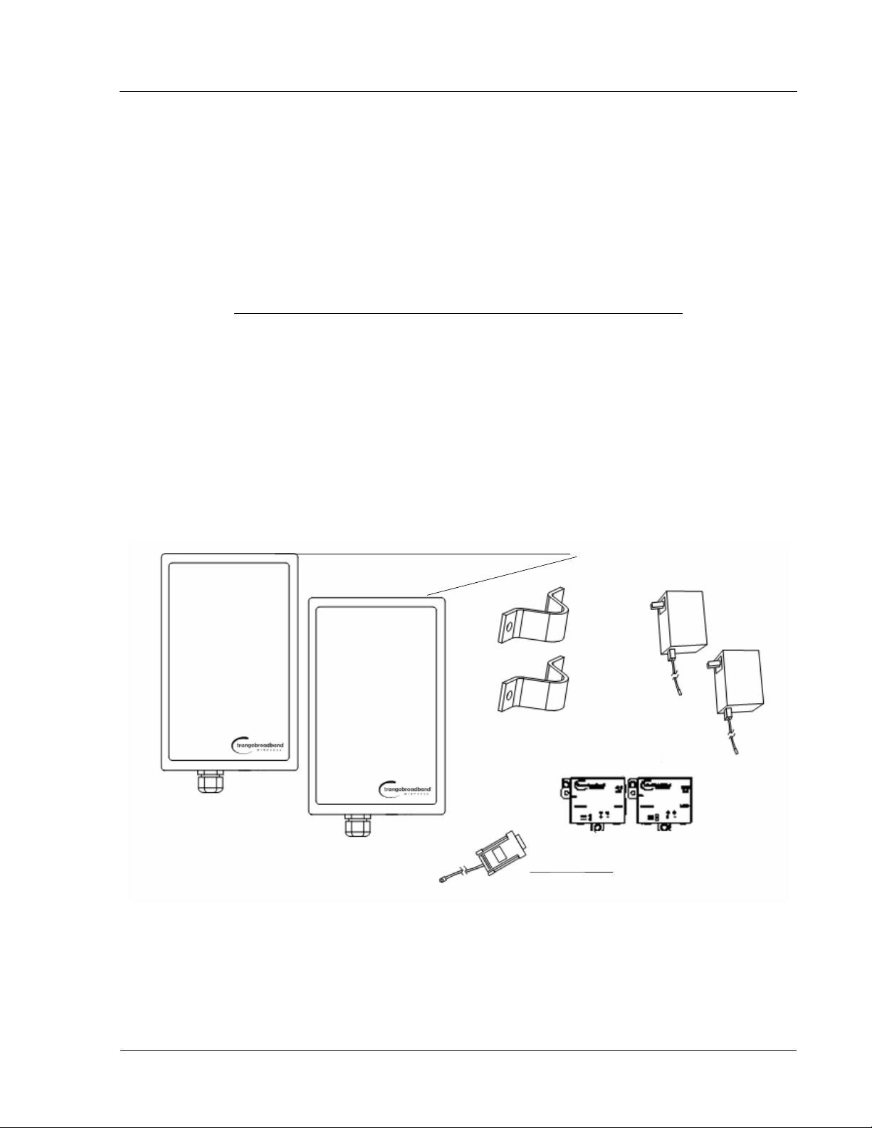
Contents
Each TrangoLINK-10 kit comes equipped with two radios, two power-over-Ethernet (PoE) J-Box, two AC adapters, a
serial programming cable, and mounting hardware. Dual-polarized integrated antennas are located behind the radomes of
both the P5830S-MU and P5830S-RU.
Antenna ISM 5725 – 5850 MHz
Integrated / Internal Antenna (18 dBi) 10 Miles (w/ 10 dB fade margin)
15" Patch Antenna (24 dBi) 20 Miles (w/ 15 dB fade margin)
36" Dish Antenna (31 dBi) 40 Miles (w/ 21 dB fade margin)
Radio (MU and RU) antenna
Power Supply (120 VAC-24 VDC)
Power-over-Ethernet Injectors
Serial Programming Cable
Figure 1:
Trango Broadband Wireless — TrangoLINK-10 User Manual Rev. E 3.0 page 1
Components of a TrangoLINK-10 System
Overview Operational Overview
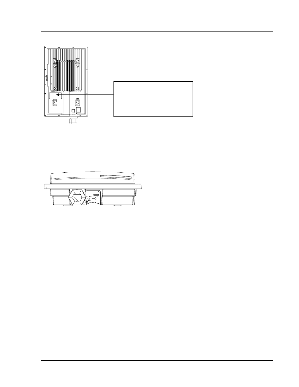
The only way to tell MUs and RUs apart is by the
model number printed on the backside product
label. This label also contains the MAC address
and serial number of the radio.
Trango Broadband Wireless
P5830S-MU Rev. A
S/N: 000001421
MAC: 00 01 DE 00 02 F3
FCC ID: NCYM5830SM
Canada: XXXXXXXXXX
This equipment has been tested and found to comply with the limits for a Class B
digital device, pursuant to Part 15 of the FCC Rules. These limits are
Figure 2: Back of Radio (Shows where MAC address can be found)
Ethernet and Serial Ports
At the bottom of the radio are two access ports: a twist-on weatherproof cable port for RJ-45 Ethernet (and PoE), and an
access cover plug for the RJ-11 serial port. Behind the access cover plug are three LEDs that provide RF link-status
information. These LEDs are discussed later in this text.
Figure 3: Bottom of Radio
Operational Overview
TrangoLINK-10 MU is a sophisticated broadband wireless device that provides a host of comprehensive tools and
functions. The MU typically resides at the managing end of the network and performs all management functions for the
associated RU.
In order to establish a wireless link between the MU and the RU, the system administrator must set up the MAC
address of the RU in the MU.
When power is first applied to a properly installed RU, it will scan all channel/polarization combinations
searching for an MU. Once the RU detects the MU it will stop scanning and lock onto the channel of the MU
and begin transmitting using maximum RF power. Before the MU can wirelessly connect to the RU, it must
authenticate the RU by verifying the MAC address and performing a ranging operation to the RU.
Upon successfully authenticating and ranging the RU, the MU will adjust the RF transmit power in the RU
based on the Target RSSI parameter in the MU. This process is referred to as “power leveling.”
At this point the MU and RU are “associated” and Ethernet traffic will pass over the wireless link.
Trango Broadband Wireless — TrangoLINK-10 User Manual Rev. E 3.0 page 2
Getting Started Connections and Power
Chapter 2 Getting Started
First unpack your MU and RU. It is recommended that you first provision and test your the radios on the bench before
deploying them in the field. This is a particularly useful exercise for the novice user.
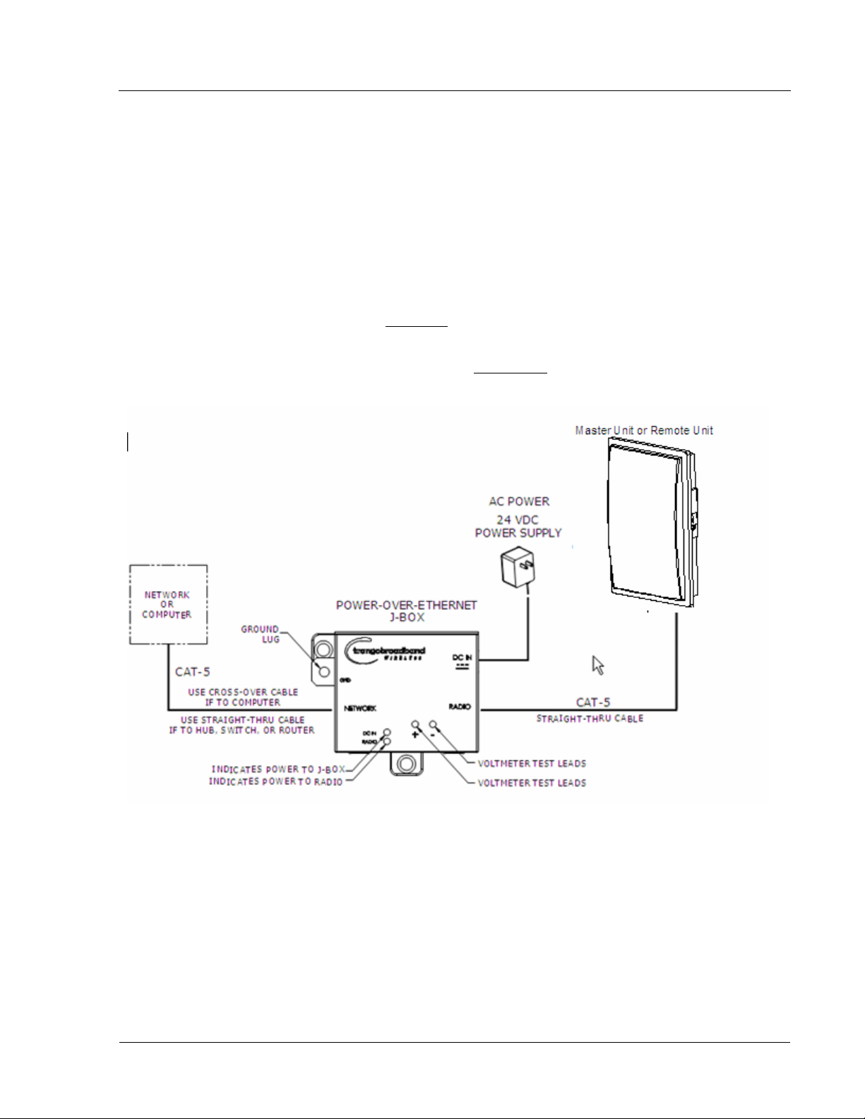
Connections and Power
Connection and powering of the radios is the same for MUs and RUs.
• Connect a Cat-5 (straight through) Ethernet cable (we recommend shielded twisted pair) between the ODU (out
door unit) port of the J-box and the RJ-45 connector on the radio. Note that this cable will carry power-overEthernet (PoE).
• If connecting to a COMPUTER, use a Cross-Over
computer’s Ethernet port.
If connecting to a HUB, SWITCH, or ROUTER, use a Straight-Thru
• Plug the AC adapter into an AC outlet.
Ethernet cable from the NET port of the J-box to the
cable.
Figure 4: Wiring Diagram
Both green LEDs on the J-box should be lit, indicating power is present at the J-box as well as the radio.
You are now ready to configure the radio via the Ethernet port.
Note: If you cannot access the radio management functions via the Ethernet port, it is possible that your PC is not
set up with a properly routable subnet. If you forget the radio’s IP address, or for some other reason cannot access
the radio via the Ethernet port, use the Serial Programming cable (supplied with each TrangoLINK kit) and attach it
to the RJ-11 port located behind the access cover on the bottom of the radio.
Trango Broadband Wireless — TrangoLINK-10 User Manual Rev. E 3.0 page 3
Getting Started Basic Configuration - Concepts and Tools
Basic Configuration - Concepts and Tools
The TrangoLINK-10 can be configured using either the Command Line Interface (CLI), or the Web Browser (HTTP)
interface. Although both methods are comprehensive and powerful, the CLI method provides slightly more functionality.
Both methods of radio configuration require an understanding of the concept of Operation Mode (Opmode).
Opmode Concept
Before logging into a radio, it is important to understand the “Opmode” concept of the TrangoLINK-10 system. MUs
and RUs can be in one of two operational modes: Opmode “On” or Opmode “Off.” When in Opmode “Off” the radio is
not transmitting, and it is not attempting to make a wireless connection. Alternatively, when in Opmode “On,” the radio
is transmitting, and is attempting to make a wireless connection.
Why is Opmode Important?
Certain functions, such as the site survey function and the RU RSSI function, can only be performed while the radio is in
Opmode “Off.” See Appendix A – Command Set Reference for a complete listing of commands, and the appropriate
Opmode(s) for each command.
Note: Factory Default Opmode for both MUs and RUs is “Off.” Default Opmode should be changed before radios
are deployed.
Note: Serial management (via the RJ-11 port) is possible on both MUs and RUs regardless of Opmode.
Note: Beginning with firmware version v1.1, TLINK-10 radios allow TCP/IP management access to both MU and
RU regardless of Opmode. V1.1 firmware also allows TCP/IP management access to the MU from the RU side of
the link (if wireless link is established).
Browser Interface
The Web browser interface is an easy-to-use, configuration and management tool. Its functionality is a subset of the
commands available in the CLI. To use the browser interface, you must have the following:
• An Ethernet connection between a PC and the radio (see figure 4)
• Setup your Ethernet PC connection to the subnet that is routable to the radio (default IP
address=192.168.100.100)
• A web browser (i.e. Microsoft Internet Explorer)
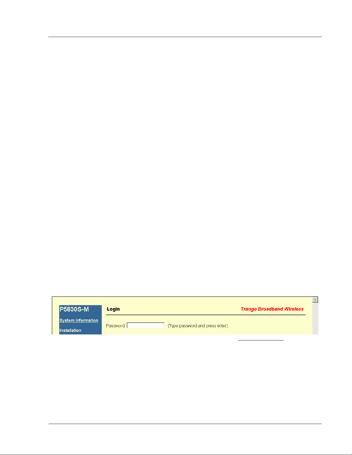
In order to use the browser interface, simply connect the radio to a PC, and type the radio’s IP address into the web
browser (i.e. Microsoft Internet Explorer). This will bring up a login page.
Type the password (default trango) and continue. This will bring up the radio’s System Information page.
Trango Broadband Wireless — TrangoLINK-10 User Manual Rev. E 3.0 page 4
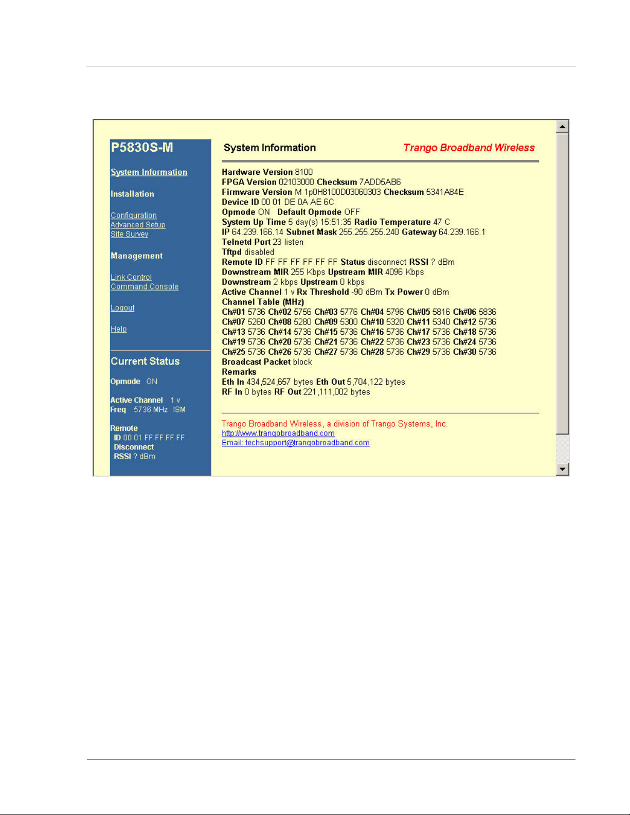
Getting Started
Log into the MU, and the System Information page with info and status appears. The equivalent command for the CLI is
sysinfo.
This particular System Information page is for a Master Unit, which is evidenced by the model number P5830S-M in the
top left. To navigate through the various screens simply click on the underlined hyperlinks on the left hand side of the
page.
The following describes the primary features and pages of the HTTP Browser interface:
Navigation Column: The blue rectangular column on the left of all pages. The top displays the model number of
the radio to which you are connected. On the bottom of the Navigation Column is the Current Status of the radio,
including current Opmode, active channel, remote ID, and remote status. The navigation column also contains all
of the hotlinks to the other pages.
System Information Page: Shows most of the basic configuration parameters of the radio. It is the first page
shown after login.
Configuration Page: The essential parameters, such as IP address, remote unit ID, channel, and polarization, are
set here.
Advanced Setup Page: RF parameters, such as Transmit Power, are set here.
Site Survey Page: From here, in Opmode “Off,” the user can conduct a spectrum analysis.
Link Control Page: With this page you can determine which SUs are connected, and how they are performing.
Trango Broadband Wireless — TrangoLINK-10 User Manual Rev. E 3.0 page 5

Getting Started
Command Console Page: Runs any console command that is not interactive (i.e. ipconfig). The results are
reported back on the HTTP screen. For a complete list of console commands, type "help" in the entry field.
Logout Link: This will end the current HTTP session with the radio.
Help Page: The Browser Interface features useful Help
pages click on the Help
link. For a complete description on the use of the Browser Interface, see Appendix A.
pages that explain all listed parameters. To access the help
Command Line Interface
Although most radio functions can be managed via the browser interface, the command line interface (CLI) does provide
more functionality. Logging into the radio via command line interface is covered here briefly, but for a complete listing
of all CLI commands see Appendix A - Command Line Interface.
Telnet
Open a command prompt (DOS) session on your PC. Open a Telnet session by typing:
telnet [ip address of radio]
Example:
C:>telnet 192.168.100.100
Note: All Trango radios are pre-configured at the factory with a default IP address of 192.168.100.100.
You will be greeted with current hardware and firmware information and prompted for a password. Type in the password
and press enter. The factory default password is trango.
To terminate a CLI session (Telnet or Serial) type the command logout.
Note: Type help or ? for a listing of all CLI commands. Type help [<command>], for the syntax of a
particular command.
See Appendix A Command Set Summary for complete description of all CLI commands.
Note: To terminate a CLI session (Telnet or Serial) type the command logout.
Note: Type help, or ?, for a listing of all CLI commands. Type help <command>, to see the syntax of that
particular command.
Troubleshooting
If you can not telnet into the radio or open an HTTP browser session, check your cable connections to ensure
proper use of cross-over vs. straight-through cable, and ensure your PC’s subnet is routable to the radio’s IP
address. If you still cannot access the radio’s management interfaces, consult the troubleshooting guide available
at http://www.trangobroadband.com/support/appnotes_web.htm
Trango Broadband Wireless — TrangoLINK-10 User Manual Rev. E 3.0 page 6
 Loading...