

Trango Broadband PTZ-900 User Manual

PTZ-900
900MHz Spread-Spectrum Digital
Wireless Pan/Tilt/Zoom Camera Control
Transmission System
™
Installation and
Operating Instructions
THE LEADER IN WIRELESS VIDEO

M-PTZ_E.p65
All rights reserved.
© 2002 Trango Systems, Inc.
15070 Avenue of Science, Suite 200
San Diego, California 92128
+1 858-653-3900
techsupport@trangosys.com
www.trangosys.com
Quick-Start Guide
1 Prior to installing the wireless link, verify proper operation of PTZ
controller (keyboard) and hard-wired receiver/driver or dome.
2 Determine the bit rate and interface (RS232 or RS485/422) of the
hard-wired system. If it is not 9600 bps and RS485/422, you will need
either to change the setting of the PTZ controller and receiver/driver
or to change the settings of the PTZ-900 equipment. See the end of
this manual for information on changing PTZ-900 internal settings
using TrangoLink software.
3 Wire the terminal block with shielded twisted-pair cable as shown
on pages 8 and 9.
4 After making the necessary adjustments to the internal settings and
cables, connect the system as shown on page 4 and test the wireless
link at short range to verify operation before installing permanently.
5 Install PTZ-900 transmitter and receiver units in desired locations
3
to 2
/
″ diameter steel pole and oriented as shown on page 3. The pole
8
must be securely mounted so that it does not move.
6
Install antennas above the enclosures and position as shown on page 3.
Important! The PTZ-900TX (transmitter) uses a special antenna con-
nector. Use only the AD900-9-P or the AO900-3-P antenna, otherwise
damage to the unit may occur.
.
Do not apply power to the transmitter unless the antenna is connected. Permanent damage to the unit may result.
The PTZ-900
TX transmitter’s effective radiated output varies
between 0.5 and 4 watts, depending on the transmit antenna
used. Although transmissions are of a short duration, it is recommended that the transmit antenna be kept at least three feet
away from nearby people. Important note to installer: This warn-
ing is for FCC exposure requirements.
PTZ-900 Installation and Operating Instructions
Use extreme care when installing antennas near power lines. You
can be killed if the antenna comes in contact with the power line.
7 Fasten the antenna cables to receiver and transmitter only finger-
tight (no more than 8 lb/in. of torque). Tighten flange around cables.
Apply a small amount of silicone to the flange openings to make a
leakproof connection.
8 Connect shielded twisted-pair interface cables to units through
flanges. Tighten flanges. Important! Power adapter must be kept dry.
9 Verify that LED is illuminated, then tighten down the enclosure’s lid
rev E Trango Systems, Inc. 3
10 To help protect against potential lightning damage use a lightning
surge arrester in line with all cabling entering a structure.
Important! Power Adapter must be kept dry.
Your Trango PTZ-900 System
Congratulations on choosing Trango Systems, Inc., to fulfill your wireless video needs.
Unpack your system carefully. If any items are missing, notify your
sales representative. If an item appears to be damaged from shipment,
replace it in its packing material and notify the shipper. Save the packaging for further storage of the equipment.
Service
If the unit ever needs repair service, contact your dealer/distributor for
return authorization and shipping instructions. Do not attempt to repair the unit yourself, as this may void the warranty.
FCC Information
ID number for the PTZ-900TX: FCC ID# NCYPTZ900TX
Important! Intentional or unintentional changes or modifications not
expressly approved by the party responsible for compliance must not
be made. Any such modifications could void the user's authority to
operate the equipment.
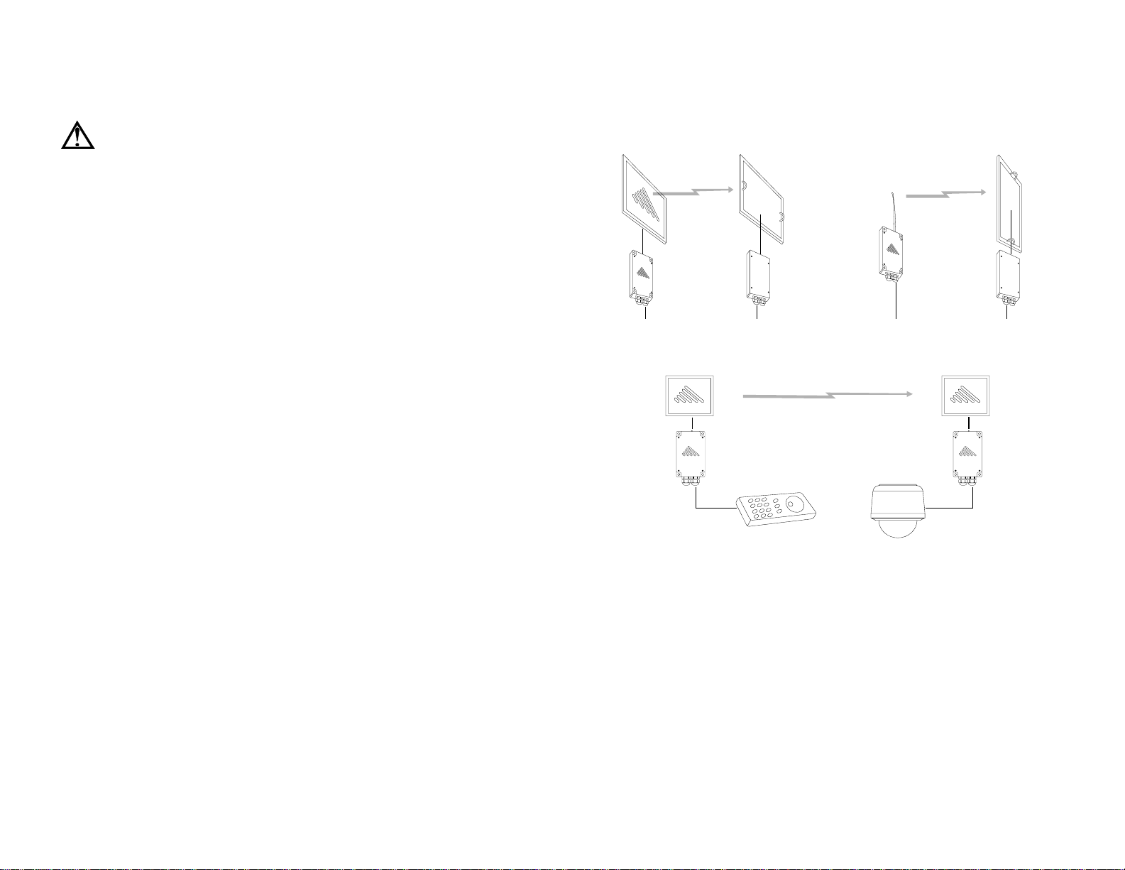
Since the patch antennas are directional, they must be aligned toward each other as shown.
The AO900-3-P antenna is available for omnidirectional coverage, for which the receiver
antenna must be vertically polarized by rotating it 90° from its normal position.
DOME or
RECEIVER DRIVER
AD900-9
PTZ-900 RX
(receiver)
shielded twisted pair
(4000¢ maximum in RS-422 mode)
AD900-9-P
PTZ-900 TX
(transmitter)
shielded twisted pair
(4000¢ maximum in RS-422 mode)
PTZ CONSOLE
This equipment generates, uses, and can radiate radio-frequency energy and, if not installed and used in accordance with these instructions, may cause harmful interference to radio communications. However, there is no guarantee that interference will not occur in a particular installation. If this equipment does cause harmful interference to
radio or television reception (which can be determined by turning the
equipment off and on) the user is encouraged to correct the interference by one of more of the following measures:
1 Reorient the receiving antenna;
2 Separate the affected equipment from the receiver;
3 Connect the affected equipment to an outlet on a different circuit
from that which the receiver is connected to;
4 Consult the dealer and/or experienced radio/TV technician for help.
Most common connection diagram for setting up a PTZ link using the PTZ-900-N system.
The dome shown may instead be a standard receiver/driver unit with a separate PTZ base.
System Description
The PTZ-900 is a professional-quality wireless transmission system
designed for sending digital, simplex (one-way) signals for pan, tilt,
zoom and camera control up to twelve miles in line-of-sight. The system employs 900MHz frequency-hopping spread-spectrum technology
with the maximum effective radiated output power allowed by the FCC
for unlicensed operation. The system will operate interference-free with
the Trango Falcon or Eagle series wireless video transmission systems
to form a complete, wireless control link.
rev E Trango Systems, Inc. 54 PTZ-900 Installation and Operating Instructions
 Loading...