

Trango Broadband M5580M-FSU User Manual

M5580M – FSU
Atlas Fox
Wireless Multi Mode Ethernet Bridge
Subscriber Unit
USER MANUAL
February 13, 2006

Table of Contents Trango
Revision 2
For
Firmware V.2p0r8
Trango Broadband Wireless — M5580M-FSU (Atlas Fox) User Manual Revision 2 page 2

Table of Contents Trango
Table of Contents
Preface..................................................................................................................................iv
FCC Information.......................................................................................................iv
Warranty Information ...............................................................................................iv
Chapter 1 Overview...............................................................................................................1
Location of RJ-45/LED Port........................................................................................ 5
Chapter 2 Getting Started.....................................................................................................6
Connections and Power............................................................................................. 6
Configuration Tools................................................................................................... 7
Troubleshooting Ethernet Connections....................................................................... 7
System Information (sysinfo) Page ............................................................................8
Chapter 3 Configuration.......................................................................................................9
Key Concepts ...........................................................................................................9
Essentials to Establish a Wireless Link........................................................................ 9
Access Point Basic Settings........................................................................................ 9
Establishing a Wireless Link....................................................................................... 9
Changing IP Address................................................................................................. 9
LEDs........................................................................................................................ 9
Power Settings .........................................................................................................9
Chapter 4 Using the HTTP Interface....................................................................................9
Chapter 5 Deployment & Installation ..................................................................................9
Site Selection ........................................................................................................... 9
Site survey...............................................................................................................9
Channel Planning...................................................................................................... 9
RSSI Command and Antenna Alignment..................................................................... 9
Mounting Hardware ..................................................................................................9
Chapter 6 Cabling and Weather Considerations................................................................9
Weatherizing............................................................................................................ 9
Chapter 7 SNMP....................................................................................................................9
Chapter 8 Firmware Upgrade Procedure ............................................................................9
Appendix B Command Set Summary ............................................................................9
Appendix A Specifications..............................................................................................9
Trango Broadband Wireless — M5580M-FSU (Atlas Fox) User Manual Revision 2 page iii

Preface
Preface
This manual covers the basic configuration and installation of the M5580M-FSU Wireless Point to Point Subscriber Unit.
The M5580M-FSU consists of a radio with an internal 8 dBi. The M5580M-FSU may be used in conjunction with an
optional FCC certified external reflector dish for extended transmission range. When using the reflector dish, professional
installation is required. Contact your sales person for more information regarding the “Professional Installation Guide.”
FCC Information
This device complies with Part 15 of the FCC Rules and Regulations. Operation is subject to the following two
conditions: (1) This device may not cause harmful interference, and (2) this device must accept any interference received,
including interference that may cause undesired operation.
This equipment has been tested and found to comply with the limits for a Class B digital device, pursuant to Part 15 of the
FCC Rules. These limits are designed to provide reasonable protection against harmful interference in a residential
installation. This equipment generates, uses, and can radiate radio-frequency energy and, if not installed and used in
accordance with these instructions, may cause harmful interference to radio communications. However, there is no
guarantee that interference will not occur in any particular installation. If this equipment does cause harmful interference
to radio or television reception, which can be determined by turning the equipment off and on, the user is encouraged to
correct the interference by one of more of the following measures:
1) Reorient the antenna.
2) Increase the separation between the affected equipment and the unit.
3) Connect the affected equipment to a power outlet on a different circuit from that which the receiver is connected to.
4) Consult the dealer and/or experienced radio/TV technician for help.
FCC ID: NCYM5580MFSU
Canada: 2945A-M5580FSU
IMPORTANT NOTE:
Intentional or unintentional changes or modifications must not be made unless under the express consent of the party
responsible for compliance. Any such modifications could void the user’s authority to operate the equipment and will
void the manufacturer’s warranty. To comply with FCC RF exposure requirements, the following antenna installation and
device operating configurations must be satisfied. The antenna for this unit must be fixed and mounted on outdoor
permanent structures with a separation distance of at least two meters from all persons. Furthermore, it must not be colocated or operating in conjunction with any other antenna or transmitter.
Warranty Information
Radios from Trango Broadband Wireless are warranted for one year from date of original purchase. Please see
www.trangobroadband.com
Trango Broadband Wireless — M5580M-FSU (Atlas Fox) User Manual Revision 2 page iv
for a complete description of warranty coverage and limitations.

Overview
Chapter 1 Overview
Each M5580M-FSU acts as an endpoint in a point to multipoint wireless Ethernet transmission system, which provides
network connectivity at, speeds up to 45 Mbps depending on the transmission distance, noise floor, and the antenna
configuration. The M5580M-FSU uses either CCK or OFDM technology coupled with Automatic Repeat request (ARQ)
for improved resistance to interference and noise.
1) M5580M-FSU unit (With integrated dual polarization 8 dBi patch antenna)
2) 20 Volt power adapter for use with 120 VAC.
3) Power over Ethernet Junction Box.
4) M ou nt in g hardware
The M5580M-FSU center frequency may be tuned from 5.736 to 5.836 GHz, allowing 6 non-overlapping channels
to ease installation. The unit utilizes Power-over-Ethernet (PoE) and is designed for outdoor environments. The
cable entry point can accommodate both Shielded twisted pair Cat5 (STP) and Unshielded twisted pair Cat5 (UTP),
however STP is recommended.
The M5580M-FSU product is comprised of the following items:
Trango Broadband Wireless — M5580M-FSU (A tlas Fox) User Manual Revision 2 page 1

Overview
Range vs. Throughput
The following table shows approximate maximum ranges (at recommended fade margins) achievable with the
M5580M-FSU when associated with an M5830S-AP in CCK mode. Ranges for OFDM modes will be published when
available.
Table – 1 Range & Throughput (CCK mode)
Antenna 3 miles 6 miles 10 miles
Integrated 8 dBi Patch
Attached to 18” Dish
(AD5800-25)
9 Mbps
(5 db fade margin)
9 Mbps
(22 db fade margin)
NA NA
9 Mbps
(15 db fade margin)
9 Mbps
(10 db fade margin)
Trango Broadband Wireless — M5580M-FSU (A tlas Fox) User Manual Revision 2 page 2
Overview
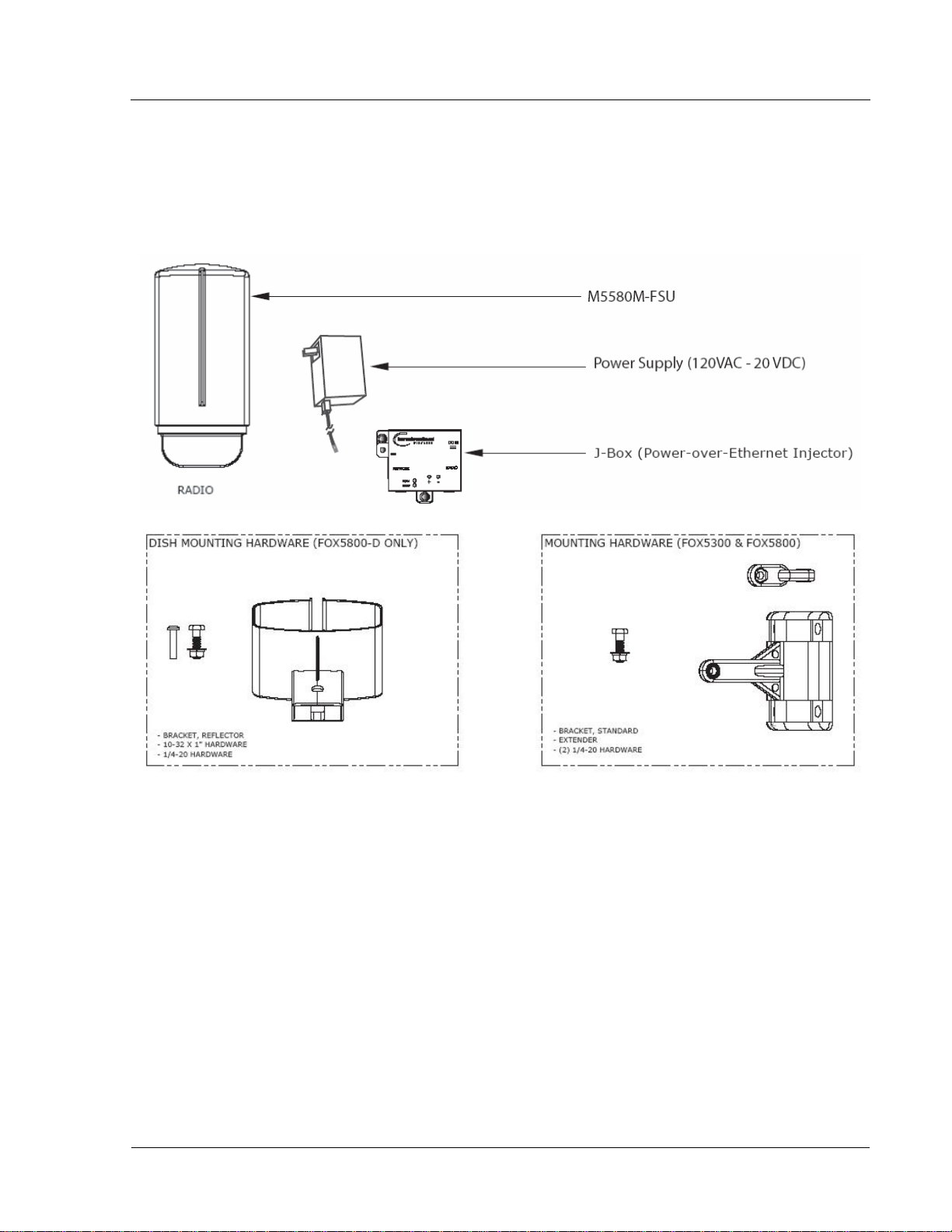
System Contents
Each kit consists of one radio with integrated antenna, one power-over-Ethernet (PoE) injector, one AC adapter,
One boot, and mounting hardware. A dual-polarized integrated antenna is located behind the radome of the
M5580M-FSU. (Dish Mounting Hardware not included with the unit)
Figure 1
Figure 2 ( NOT INCLUDED) Figure 3
Trango Broadband Wireless — M5580M-FSU (A tlas Fox) User Manual Revision 2 page 3
Overview
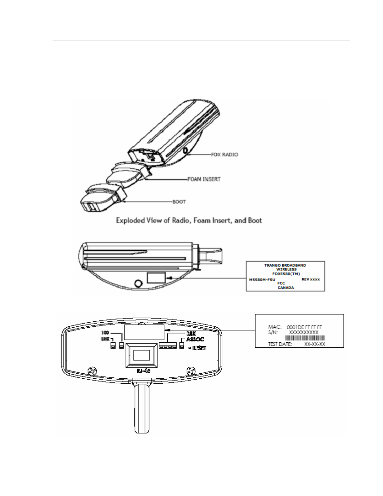
Location of Serial Number & MAC Address
The serial number and MAC address label can be found on the back of each radio. The serial number and MAC address
is also provided on the system information screen. (See figure 4 & 5 below)
Figure 4
Figure 5
Trango Broadband Wireless — M5580M-FSU (A tlas Fox) User Manual Revision 2 page 4
Overview
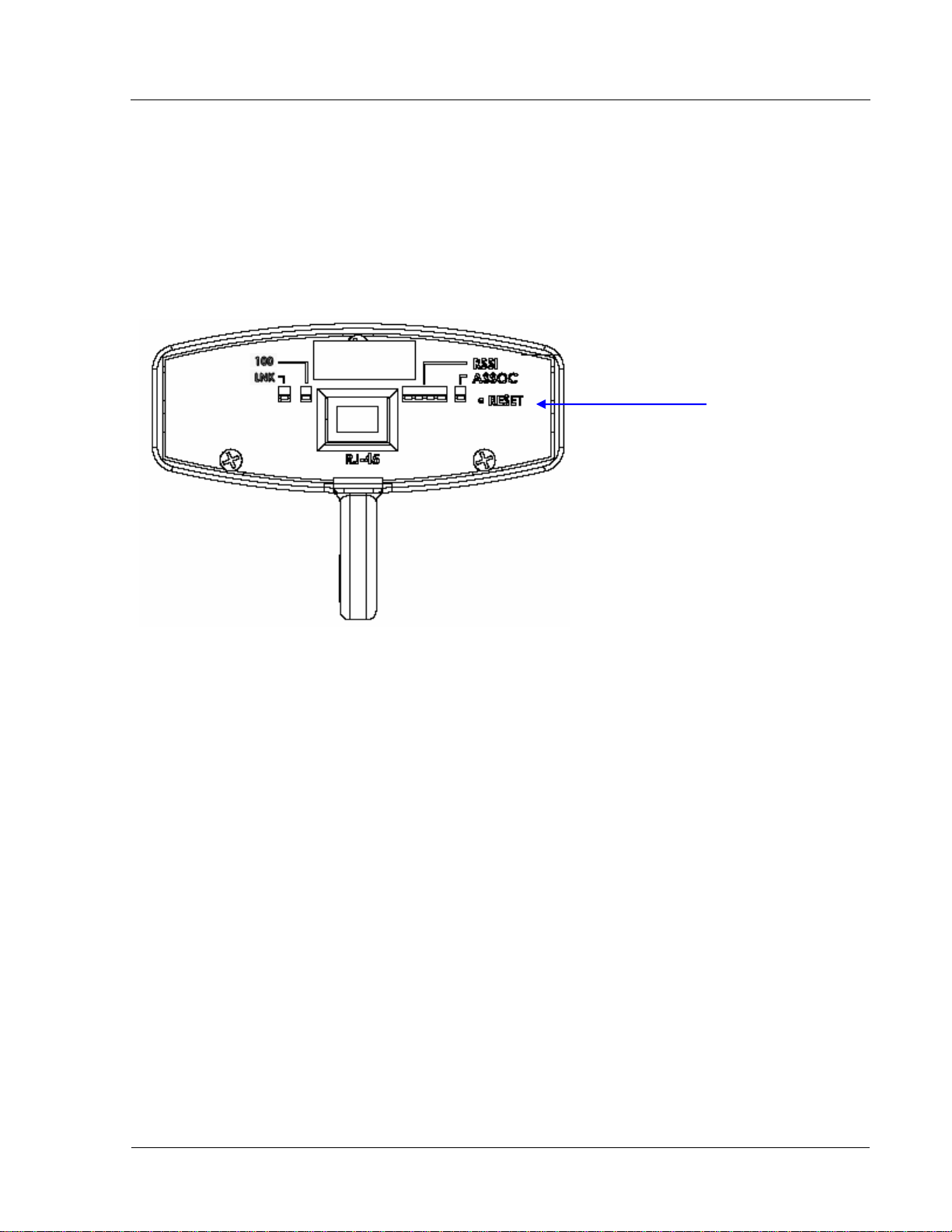
Location of RJ-45/LED Port
The RJ-45 connector, diagnostic LEDs, and reset button are located at the bottom of the radio. Functionality of the LEDs
is described later in this text. The reset button, resets all configuration settings (including IP address and password) back
to factory default. Hold the reset button down for 5 seconds (until amber lights flash) while unit is powered on.
Figure 6
Reset Button
Trango Broadband Wireless — M5580M-FSU (A tlas Fox) User Manual Revision 2 page 5
Getting Started
Chapter 2 Getting Started
It is recommended that you first provision and test your the radios on the bench before deploying them in the
field. This is a particularly useful exercise for the novice user.
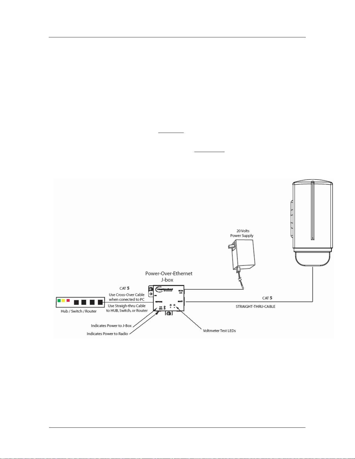
Connections and Power
• Connect a Cat-5 (straight through) Ethernet cable (we recommend shielded twisted pair) between the
ODU (out door unit) port of the J-box and the RJ-45 connector on the radio. Note that this cable will
carry power-over-Ethernet (PoE).
• If connecting to a COMPUTER, use a Cross-Over
computer’s Ethernet port.
If connecting to a HUB, SWITCH, or ROUTER, use a Straight-Thru
• Plug the AC adapter into an AC outlet.
Figure 7
Ethernet cable from the NET port of the J-box to the
cable.
Both green LEDs on the J-box should be lit, indicating power is present at the PoE box as well as at the radio.
The Radio’s Power LED may take several seconds before lighting. It will require approximately 45 seconds for
the radio to boot and be ready for configuration via the Ethernet port.
Note: If voltage falls below 16 volts, the power LED will go off but the Radio LED will stay on. The radio
can operate down to 10.5 volts.
Trango Broadband Wireless — M5580M-FSU (A tlas Fox) User Manual Revision 2 page 6
 Loading...