

Page 1

M2400S™
2.4 GHz Wireless Broadband System
USER MANUAL
October 18, 2004
Revision A
for Firmware Version 1.0
Page 2

Table of Contents Trango
Table of Contents
Preface ........................................................................................................................................................................... iv
FCC Information ....................................................................................................................................................... iv
Warranty Information................................................................................................................................................ iv
Firmware Notifications.............................................................................................................................................. iv
Section 1 Introduction..................................................................................................................................................... 1
Overview .................................................................................................................................................................... 1
SmartPolling™ & Bandwidth Throttling.................................................................................................................... 2
Auto-retransmit Feature (ARQ).................................................................................................................................. 2
Section 2 Hardware Overview ........................................................................................................................................ 3
M2400S AP and SU Hardware Components.............................................................................................................. 3
Section 3 Getting Started ................................................................................................................................................ 4
Connections and Power .............................................................................................................................................. 4
Radio Management Concepts..................................................................................................................................... 5
Browser Interface ....................................................................................................................................................... 6
Command Line Interface ............................................................................................................................................ 9
Telnet...................................................................................................................................................................... 9
Troubleshooting.................................................................................................................................................... 10
Section 4 Basic Configuration via Browser Interface................................................................................................... 11
Configuring the AP Subscriber Unit Database ......................................................................................................... 11
Creating an SU in the SU Database………………………………………………………………………………….... 12
Configure Other Basic AP Parameters ..................................................................................................................... 13
Configure Basic SU Parameters ............................................................................................................................... 15
Link Control Page..................................................................................................................................................... 16
RF Link Loopback Test............................................................................................................................................ 17
SU Ranging Test....................................................................................................................................................... 18
Advanced Setup Page ............................................................................................................................................... 18
Other Key Parameters............................................................................................................................................... 19
Site Survey Page....................................................................................................................................................... 20
Basic Configuration via CLI......................................................................................................................................... 21
Access Point Basic Settings...................................................................................................................................... 21
Subscriber Unit Database Settings............................................................................................................................ 24
Subscriber Unit Basic Settings ................................................................................................................................. 25
Section 5 Mounting Hardware...................................................................................................................................... 28
Cabling and Grounding Considerations.................................................................................................................... 29
Section 6 Deployment................................................................................................................................................... 30
Site Selection............................................................................................................................................................ 30
Site Survey ............................................................................................................................................................... 30
AP Search and SU Antenna Alignment.................................................................................................................... 31
Link Management Commands.................................................................................................................................. 33
ARQ with Selected Repeat and Multirate Feature.................................................................................................... 36
Section 7 Management.................................................................................................................................................. 36
Radio Management Access Via TCP/IP................................................................................................................... 36
SU Management from AP ........................................................................................................................................ 36
Loading Multiple SU’s into SUDB using DLOAD Command................................................................................. 37
SNMP ....................................................................................................................................................................... 38
Objects for Monitoring and Control ......................................................................................................................... 38
SNMP Setup ............................................................................................................................................................. 38
Appendix A Command Set Reference .......................................................................................................................... 40
Appendix B Specifications ........................................................................................................................................... 44
Trango Broadband Wireless — M2400S User Manual Rev. A page ii
Page 3

Table of Figures Trango
Table of Figures
Figure 1: Typical Deployment....................................................................................................................................... 1
Figure 2: Basic Components of an M2400S Radio........................................................................................................ 3
Figure 3: Bottom of Radio............................................................................................................................................. 3
Figure 4: Back of Radio................................................................................................................................................. 4
Figure 5: Side of Radio & Location of Reverse Polarity SMA Connector .................................................................... 4
Figure 6: Wiring Diagram.............................................................................................................................................. 5
Figure 7: LED Summary.............................................................................................................................................. 16
Figure 8: M2400S Mounting Hardware Assembly...................................................................................................... 28
Figure 9: Articulation for M2400S with Mono Pod Mount (not supplied).................................................................. 28
Figure 10: Grounding of Radio.................................................................................................................................... 29
Trango Broadband Wireless — M2400S User Manual Rev A page iii
Page 4

Preface
Preface
This manual covers basic configuration and installation of the M2400S Wireless Broadband System and applies to
the following radio part numbers:
M2400S-AP 2.4 GHz Access Point
M2400S-SU 2.4 GHz Subscriber Unit
FCC Information
This device complies with Part 15 of FCC Rules and Regulations. Operation is subject to the following two
conditions: (1) This device may not cause harmful interference, and (2) this device must accept any interference
received, including interference that may cause undesired operation.
This equipment has been tested and found to comply with the limits for a Class B digital device, pursuant to Part 15
of the FCC Rules. These limits are designed to provide reasonable protection against harmful interference in a
residential installation. This equipment generates, uses, and radiates radio-frequency energy; if not installed and
used in accordance with these instructions, the unit may cause harmful interference to radio communications.
However, there is no guarantee that interference will not occur in any particular installation. If this equipment does
cause harmful interference to radio or television reception, which can be determined by turning the equipment off
and on, the user is encouraged to correct the interference by one or more of the following measures:
1) Reorient the antenna.
2) Increase the separation between the affected equipment and the unit.
3) Connect the affected equipment to a power outlet on a different circuit from the one the receiver is connected
to.
4) Consult the dealer and/or experienced radio/TV technician for help.
FCC ID: NCYM2400S
Canada:
IMPORTANT NOTE: Intentional or unintentional changes or modifications must not be made unless under the
express consent of the party responsible for compliance. Any such modifications could void the user’s authority to
operate the equipment and will void the manufacturer’s warranty. To comply with FCC RF exposure requirements,
the following antenna installation and device operating configurations must be satisfied. The antenna for this unit
must be fixed and mounted on an outdoor permanent structure with a minimum separation distance of two meters
from any persons. Furthermore, it must not be co-located or operated in conjunction with any other antenna or
transmitter.
Warranty Information
Radios from Trango Broadband Wireless are warranted for one year from date of purchase. Please see
www.trangobroadband.com
for a complete description of warranty coverage and limitations.
Firmware Notifications
To receive email notifications regarding firmware upgrades and product announcements, register at
http://www.trangobroadband.com/mailinglist/mailingListAdd.aspx
Trango Broadband Wireless — M2400S User Manual Rev A page iv
Page 5
Introduction
Section 1 Introduction
Your Trango Broadband M2400S radio system provides a reliable and robust means to deliver broadband access to
a wide geographic region through wireless Ethernet connectivity. This section will familiarize you with basic
operational concepts, as well as an overview of the various components and hardware of the M2400S system.
Overview
The M2400S is a highly versatile and cost effective outdoor point-to-multipoint solution for wireless broadband
service providers’ enterprise connectivity applications. The M2400S delivers 5 Mbps over the air, and operates in
the 2.4 GHz license free ISM band. Each radio includes an integrated dual polarized (horizontal and vertical)
antenna, as well as a connector for the attachment of an external antenna, such as a Yagi or an omni style antenna.
Note: If you are going to install an external antenna, refer to the M2400S Professional Installation Guide.
Contact Technical Support for access to the Professional Installation Guide.
The M2400S system consists of two types of radios: Access Points (APs) and Subscriber Units (SUs). Up to 126
subscriber units can be supported by a single AP, which acts as a hub in a star configuration. The AP delivers
wireless broadband service (Ethernet connectivity) to one or more SUs according to a proprietary adaptive dynamic
polling algorithm called SMARTPolling™. Network operators can co-locate multiple APs at a single cell site, thus
increasing the aggregate throughput available at each wireless point-of-presence (POP).
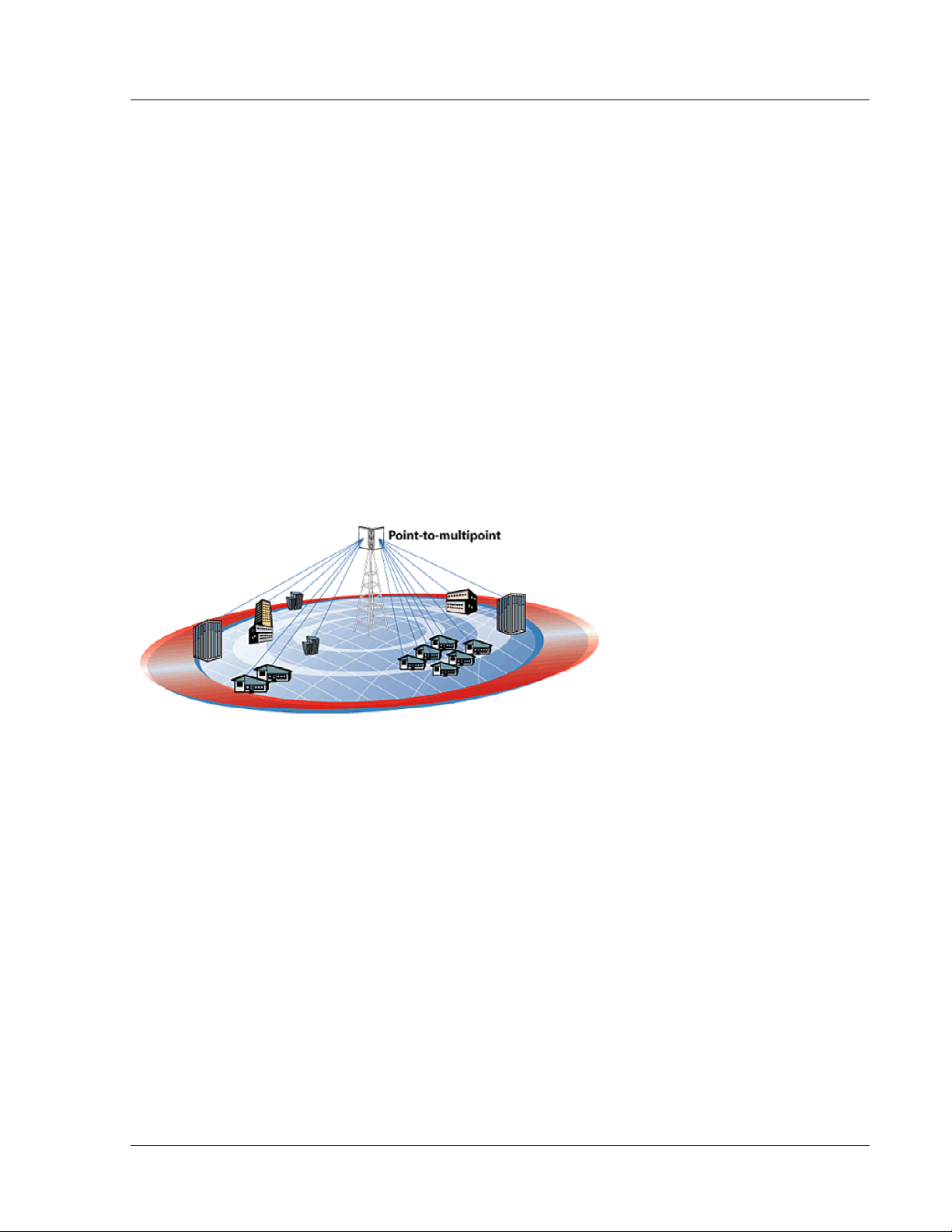
Figure 1: Typical Deployment
The AP typically resides at the center of the point-to-multipoint (PMP) network. It performs all management
functions, including the allocation of bandwidth for all associated SUs. The M2400S AP provides a host of
comprehensive tools and functions.
The M2400S system is classified as a Layer 2 multi-point bridge, thus all forms of Ethernet traffic will pass
seamlessly over the system. There is no limitation on the number of IP addresses or hardware devices to which an
individual subscriber unit may be connected.
Authentication of Subscriber Units is performed using a secure proprietary method, which is based on the MAC
address of the Subscriber Unit. In order to establish a wireless link the MAC address of the SU must be present in
the Access Point’s Subscriber Unit Database (SUDB).
Both APs and SUs are IP addressable and can be managed remotely across the network. Users can manage the
radios using the telnet command line interface or the graphical HTTP browser interface. The M2400S also
provides remote firmware upgrade capability utilizing TFTP. APs include a full featured SNMP agent for the
monitoring and controlling of both APs and SUs via SNMP.
The M2400S radios are powered using "power-over-Ethernet" for ease and low-cost installation. A single Cat-5
cable carries both Ethernet and DC power to the radio.
Trango Broadband Wireless — User Manual M2400S Rev. A
Page 1
Page 6

Introduction
Both APs and SUs feature a handy "site survey" tool to check for interference, as well as RSSI tools for optimizing
antenna positioning. The M2400S also features variable receiver threshold, full power control, dual polarized
antennas, and various link diagnostic tools.
SmartPolling™ & Bandwidth Throttling
One of the major advantages of the M2400S system is the ability of the AP to handle multiple SU
connections and share the 5 Mbps data throughput efficiently. Bandwidth allocation is managed by the
AP’s SMARTPolling™ algorithm according to provisioning rules set up by the system administrator. The
AP polls each SU in a round robin format to determine if the SU has data to transfer. The SU only
transmits the data “upstream” to the AP when the AP gives authorization via a “transmit grant.” The SU
passes every “downstream” data packet from the AP and identifies packets intended for it. In order for an
SU to communicate with an AP, the system administrator must first add the MAC address and ID number
of the SU to the SUDB in the AP. The SMARTPolling™ algorithm will poll active SUs more often, thus
making the most efficient use of the 5 Mbps bandwidth. Several other parameters are considered in the
Smart Polling™ algorithm, including upstream/downstream committed information rate (CIR),
upstream/downstream maximum information rate (MIR), and Priority Setting.
Each of the above parameters is set in the AP by the system administrator and cannot be controlled at the
SU. These parameters will be covered in greater detail later in this text.
When power is first applied to a properly installed SU, it will scan all available channels listening for a
grant from an AP that has a matching Base ID and the SU’s MAC in the its SUDB. The SU will then stop
on that channel and respond to the AP using maximum RF power. Before the AP can add the SU to the
polling list, it must authenticate the SU by verifying the MAC address and performing a ranging operation
to the SU. Upon successfully locating and ranging the SU, the AP will then add the SU to the normal
polling list. Once the AP is regularly polling the SU, the SU is said to be “associated” to the AP.
Once associated, the AP will send a command to the SU to adjust the SU’s RF transmit power based on the Target
RSSI parameter set in the AP. This process is referred to as “power leveling.”
System operators may limit allowable bandwidth to specific customers utilizing the built-in CIR and MIR settings
(measured in kbps) for each SU.
Auto-retransmit Feature (ARQ)
The M2400S features ARQ or “Automatic Repeat Request,” which is the ability to correct for missing or corrupted
packets of data by requesting the sending radio to re-transmit the data. Both the AP and SU units implement a form
of ARQ known as “ARQ with Selected Repeat.” The use of ARQ is especially important in areas of high
interference. The ARQ feature can be turned on or off.
Trango Broadband Wireless — User Manual M2400S Rev. A
Page 2
Page 7
Hardware Overview
Section 2 Hardware Overview
This section provides detail about each radio in the M2400S family. Each radio in the M2400S family includes a
built-in, electronically switchable, dual-polarized antenna, as well as a reverse polarity SMA connector for the
attachment of an external antenna. For ease of installation all units are designed for outdoor installation and
powered by power-over-Ethernet (POE). The M2400S Access Point and Subscriber Units provide channels of
operation within the 2400 MHz ISM band, which spans from 2400 MHz to 2483 MHz. Default channel spacing is
10 MHz, allowing for 8 non-overlapping channels.
M2400S AP and SU Hardware Components
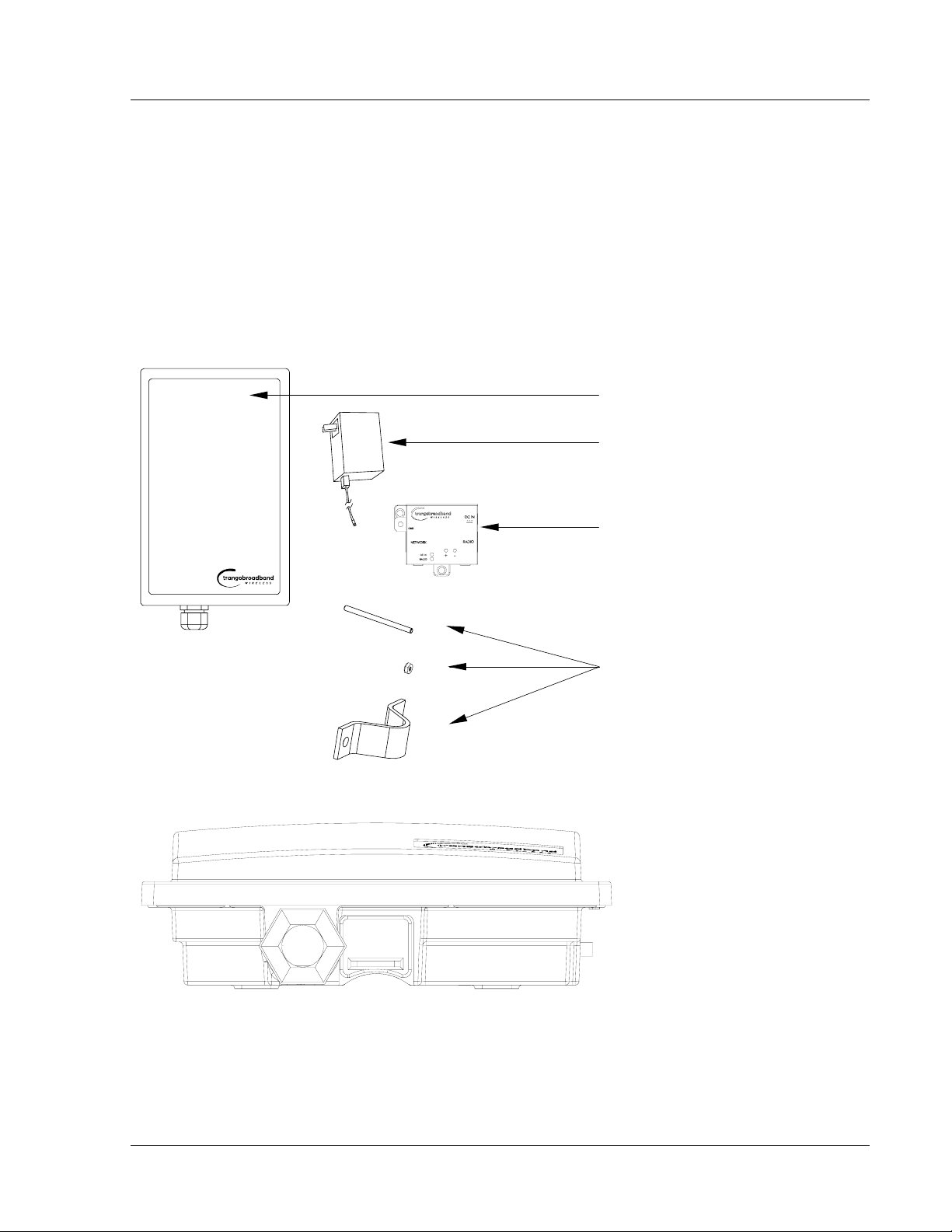
Each radio comes equipped with, a power-over-Ethernet (PoE) J-Box, an AC adapter, and mounting hardware.
Radio (AP or SU) antenna
Power Supply (120 VAC-20 VDC)
J-Box (Power-over-Ethernet Injector)
4X
8X
2X
Figure 2: Basic Components of an M2400S Radio
Figure 3: Bottom of Radio
Mounting Hardware
At the bottom of the M2400S are two access ports: a twist-on weatherproof cable port for RJ-45 Ethernet (and
PoE), and a translucent access cover plug over the unit’s diagnostic LEDs and reset button. The LEDs will be
discussed later in this text.
Trango Broadband Wireless — User Manual M2400S Rev. A
Page 3
Page 8
Getting Started
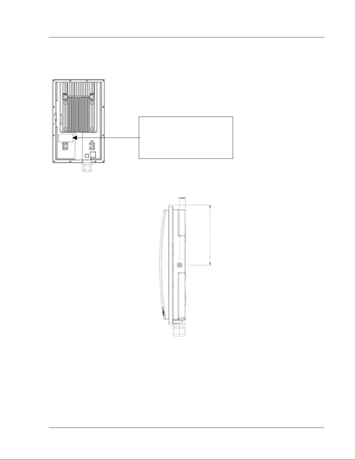
The radio’s model number, FCC ID, MAC ID, and Serial # are located on the backside of the radio.
Trango Broadband Wireless
M24000S-AP Rev. A
S/N: 00000XXXX
MAC: 00 01 DE 00 02 F3
FCC ID: NCYM2400S
Canada: XXXXXXXXXX
This equipment has been tested and found to comply with the limits for a Class B digital device,
pursuant to Part 15 of the FCC Rules. These limits are
Figure 4: Back of Radio
.600
6.300
Figure 5: Side of Radio & Location of Reverse Polarity SMA Connector
Section 3 Getting Started
This section explains how to power your radios, establish TCP/IP connectivity to the radios, as well as how to
access the HTTP browser and the command line interfaces.
Connections and Power
Connection and powering of radios is the same for APs and SUs.
Trango Broadband Wireless — User Manual M2400S Rev. A
Page 4
Page 9
Getting Started
r
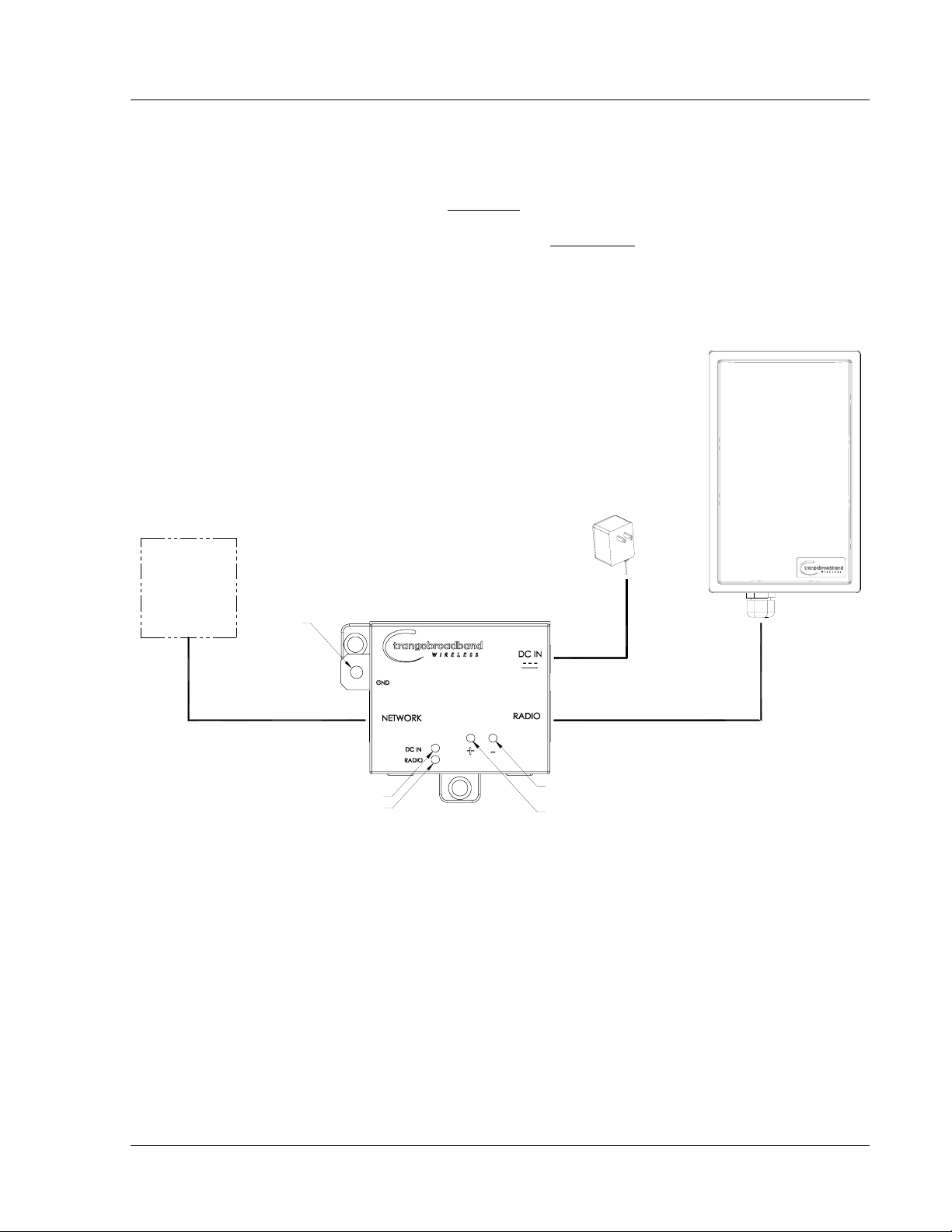
• Connect a Cat-5 (straight through) Ethernet cable (we recommend shielded twisted pair) between the
Radio port of the J-box and the RJ-45 connector on the radio. Note: this cable will carry power-overEthernet (PoE).
• NETWORK port connection is as follows:
If connecting to a COMPUTER, use a Cross-Over
to the computer’s Ethernet port.
If connecting to a HUB, SWITCH, or ROUTER, use a Straight-Thru
• Plug the AC adapter into an AC outlet.
• Use Ground Lug to ground PoE device and shielded CAT5.
• Use voltmeter contacts to check line voltage (can be done with or without load).
Ethernet cable from the NETWORK port of the J-box
cable.
M2400S (AP o
AC POWER
20 VOLT POWER
SUPP LY
NETWORK
OR
COMPUTER
GROUND
LUG
CAT-5
USE STRAIGHT-THRU CABLE
IF TO HUB, SWITCH, OR ROUTER
USE CROSS-OVER CABLE
IF TO COMPUTER
INDICATES POWER TO J-BOX
INDICATES POWER TO RADIO
POWER-OVER-ETHERNET
J-BOX
CAT-5
STRAIGHT-THRU CABLE
VOLTMETER TEST LEADS
VOLTMETER TEST LEADS
Figure 6: Wiring Diagram
Both green LEDs on the J-box should be lit, indicating power is present at the J-box as well as the radio.
You are now ready to configure the radio via the Ethernet port.
SU)
Radio Management Concepts
Proper connections to the radios and careful IP/routing & planning will enable the network administrator to access
and manage the radios remotely over the network via TCP/IP. Radio management over TCP/IP can be performed
from computers connected to the Ethernet side of each radio. Computers connected to the AP can manage the SU
over their wireless connection. Likewise, computers connected to the SU can manage the AP, provided that switch
7 (TCP/IP access to AP from SU) is enabled on the AP. Switches will be covered later in this text.
Trango Broadband Wireless — User Manual M2400S Rev. A
Page 5
Page 10

Getting Started
Opmode
To fully understand radio management for the M2400S system, it is important to be familiar with the concept of
operation mode or “Opmode.”
APs and SUs can be in one of two Opmodes (“ON” or “OFF”). When in Opmode “OFF”, the AP is not
transmitting and is not attempting to associate with any SUs. Alternatively, when in Opmode “ON,” the radio is
transmitting and attempting to become associated.
Several functions, such as the site survey function and the SU RSSI function, can only be performed while the radio
is in a particular Opmode. See Appendix D (Command Set Reference) for a complete listing of commands, and the
appropriate Opmode for each command.
Switch Settings
M2400S firmware includes several “switches,” which are used to set certain operational parameters of the radios.
Switch settings can be changed via the HTTP browser interface or the Command Line Interface. For purposes of
radio TCP/IP management, the following four switches are important:
Switch 2 (SU) - TCP/IP access to SU from the AP’s side of network requires that the SU’s switch 2 (SW 2 –
TCP/IP for AP) be ON. Default setting for SW 2 (from factory) is ON.
Switch 5 (AP and SU) – In order to utilize the radio’s HTTP Browser interface, switch 5 (SW 5 – Enable HTTP)
must be ON. Default setting for SW 5 (from factory) is ON.
Switch 6 (SU) - TCP/IP access from Ethernet port of SU while in Opmode “ON,” requires that switch 6 (SW 6 –
TCP/IP Service for Ethernet Port) be ON. Default setting for SW 6 (from factory) is ON. If SW 6 is OFF,
TCP/IP access to SU from it’s Ethernet port is possible only if SU’s Opmode is “OFF.”
Switch 7 (AP) – TCP/IP access to AP from SU’s side of network requires that the AP’s switch 7 (SW 7 –
TCP/IP for SU) be ON. Default setting for SW 7 (from factory) is ON.
Passwords
In order to log into an M2400S radio (either through telnet or through the web browser interface), the user must
know the IP address and password. Both AP’s and SU’s feature two levels of passwords: Read Write (RW) and
Read Only (RO). Be sure to change both passwords (RW and RO) prior to deployment of your radios on a live
network. Passwords can be changed using the “password ro and password rw command in either the CLI interface
or in the command console of the browser interface.
Reset Button
Pressing the reset button will reset the radio’s IP address and password back to factory defaults.
Default IP (192.168.100.100) Default Password (trango)
Browser Interface
The M2400S (both AP and SU) features a convenient and easy-to-use web based configuration and management
tool. No additional software is needed on your computer other than a web browser. Most functions can be
performed using the browser interface, although several functions can only be performed using command line
interface (CLI). The browser interface also includes a “command console” page that allows the user to enter most
CLI commands without leaving the browser interface.
To use the browser interface, the following must be present:
• An Ethernet connection between a PC and the radio
• Ethernet PC connection with IP/subnet that is routable to the radio
• SW 5 ON (default)
• A web browser on the PC (i.e. Microsoft Internet Explorer)
Trango Broadband Wireless — User Manual M2400S Rev. A
Page 6
Page 11
Getting Started
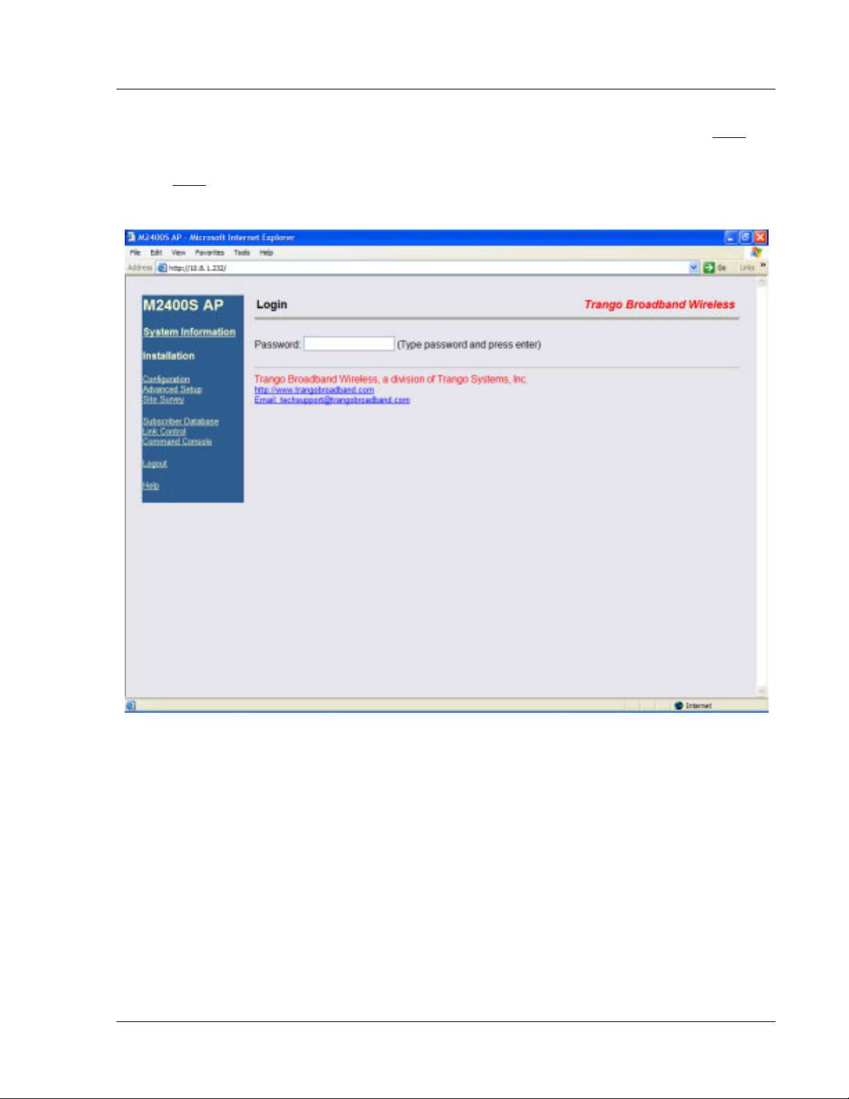
In order to use the browser interface, simply connect the radio to a PC and type the radio’s IP address (default IP
address=192.168.100.100) into the web browser (i.e. Microsoft Internet Explorer). This will bring up the Login
page.
NOTE: Login
pages for AP and SU are similar.
Browser Interface Login Page
Type the password (default trango) and continue. This will bring up the radio’s system information page.
Trango Broadband Wireless — User Manual M2400S Rev. A
Page 7
Page 12
Getting Started
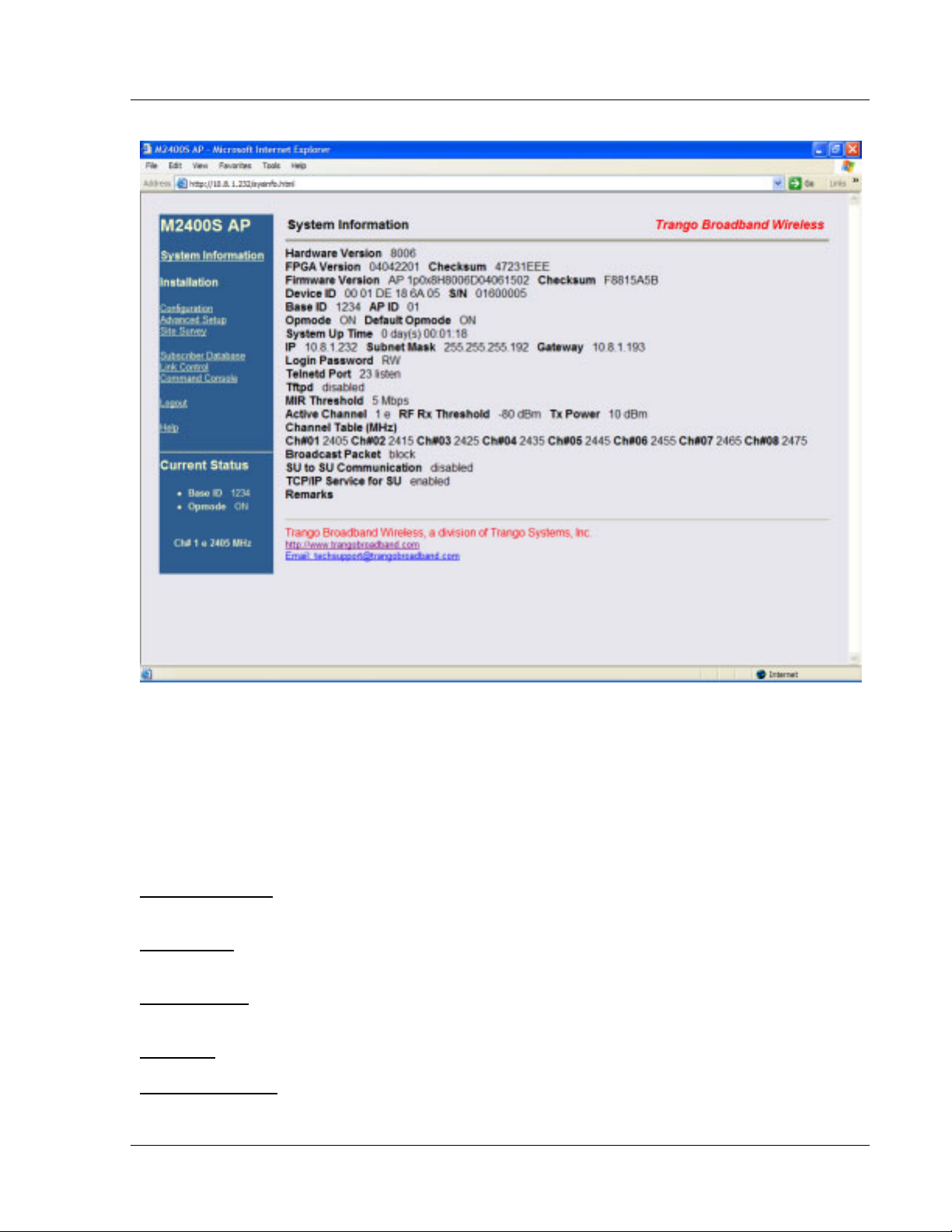
Web Browser System Information Page
! Note: System Information screen for the Subscriber Unit is similar and is covered in detail later in this text.
Primary Features and Pages of the Browser Interface
Navigation Column: Each page features a navigation column, which runs along the left-hand side of the page.
The model number of the radio is listed at the top of the navigation column. On the bottom of the navigation
column is the Current Status of the radio that includes its Base ID, current Opmode, channel, antenna selection, and
frequency.
The navigation column also features links to each of the following pages:
System Information
shown after login.
Configuration
are set here.
Advanced Setup
center frequencies are set here.
Site Survey
: With Opmode “OFF,” the user can conduct a spectrum analysis using this page.
Subscriber Database
: This page shows most of the basic configuration parameters of the radio. It is the first page
: The essential parameters, such as Base ID, IP, subnet, gateway, channel, and antenna polarization
: The advanced RF parameters, such as transmit power, receiver threshold control, and channel
: This is the page for defining which SUs can associate to the AP.
Trango Broadband Wireless — User Manual M2400S Rev. A
Page 8
Page 13

Getting Started
Link Control: This page shows which SUs are associated. This page also provides several tools for evaluating the
quality of the wireless link.
Command Console
: From this page, the user can run any console command that is not interactive (i.e. ipconfig)
or time sensitive (su linktest). For a complete list of console commands, type help or ? in the entry field.
Logout
: This link will end the current browser session with the radio.
Help
: The Browser Interface features useful Help pages which explain all listed parameters. To access the help
pages click on the Help link.
Command Line Interface
Although most radio functions can be managed via the browser interface, the command line interface (CLI)
provides slightly more functionality and is usually the management tool of choice for experienced users. The CLI
can be accessed through Telnet.
Telnet
Open a command prompt (DOS) session on your PC. Open a telnet session by typing:
telnet [ip address of radio]
All Trango radios are pre-configured at the factory with a default IP address of 192.168.100.100. The factory
default password is trango. Once you connect to the radio you will be greeted with current hardware and firmware
information and prompted for a password. Type in the read-write (RW) password and press enter.
Example:
C:>telnet 192.168.100.100
Welcome to Trango Broadband Wireless M2400S-AP 1p0X21H0006D04081903
Password:
#>
To terminate a CLI session (Telnet or Serial) type the command logout.
! Note: Type help or ? for a listing of all CLI commands. Type help <command> for the syntax of a particular
command.
Example (to view a list of all commands that start with su)
#> ? su
su [all | <suid, 1..126>]
su info <suid, 1..126>
su linktest <suid, 1..126>
su password <suid|all> <rw|ro> <new password> <new password>
su ping <suid, 1..126>
su reboot <suid|all>
su sw <suid|all> <sw#, 0..7> <on | off>
su testrflink <suid, 1..126> <r>
su testrflink <all> <r>
sudb add <suid, 1..126> <pr|re> <device id,hex>
sudb cirmir <<suid>|all> <cir dn> <cir up> <mir dn> <mir up>
sudb defaultcirmir [<cir dn> <cir up> <mir dn> <mir up>]
sudb delete <<suid>|all>
sudb dload
sudb gid <<suid>|all> <0..15>
sudb view
survey <time, 1..10 sec> <antenna, h|v|e>
Trango Broadband Wireless — User Manual M2400S Rev. A
Page 9
Page 14

Getting Started
#>
! NOTE: The majority of the CLI commands will be covered throughout this text as well as in Appendix A −
Command Set Reference.
Troubleshooting
If you cannot telnet into the radio or open a browser session, check cable connections, ensure proper use of crossover vs. straight-through cable, and ensure PC’s subnet is routable to radio’s IP address. If you still cannot access
the radio’s management interfaces, consult the troubleshooting guide, which is available at
www.trangobroadband.com
in the Technical Support area of the website.
Trango Broadband Wireless — User Manual M2400S Rev. A
Page 10
Page 15

Basic Configuration via Browser Interface
Section 4 Basic Configuration via Browser Interface
This section describes a few more basic concepts and how to establish a basic wireless link between AP and SU
using the Browser (HTTP) Interface. This section is written to address only the most basic steps in establishing a
link in the lab, or a bench-top environment. It is highly recommended to read the other sections of this manual to
gain an understanding of all important configuration parameters and procedures prior to deploying any wireless
equipment.
In this section you will:
• Learn about AP and SU Basic Configuration Screens and Parameters
• Populate AP’s Subscriber Unit Data Base (SUDB) with at least one SU
• Configure Other Basic AP Parameters
• Configure Basic SU Parameters
• Establish a Wireless Link
• Evaluate Link Quality
The M2400S uses the concept of “association” to indicate that the AP and SU’s are communicating. If all
parameters are properly set, the AP will begin actively searching for the SU’s in its SUDB. Once an active SU is
detected, the authentication and association process will begin.
Essentials in Establish inga Wireless Link with M2400S Series Radios
• Base ID in AP and SU must match
• MAC Address of SU must be entered into the AP’s SUDB
• SU must be set to “autoscan” all channels(switch 1), or be fixed on same channel as AP.
• AP must be in Opmode “ON”
• SU must be in Opmode “ON”
• Adequate signal strength must be received at each radio
If all of these parameters are met, the wireless link will automatically establish itself and Ethernet traffic will begin
to pass between the radios.
! Note: This section utilizes the Browser Interface as the configuration tool. For the equivalent procedure using
CLI commands, see Section 5.
Configuring the AP Subscriber Unit Database (SUDB)
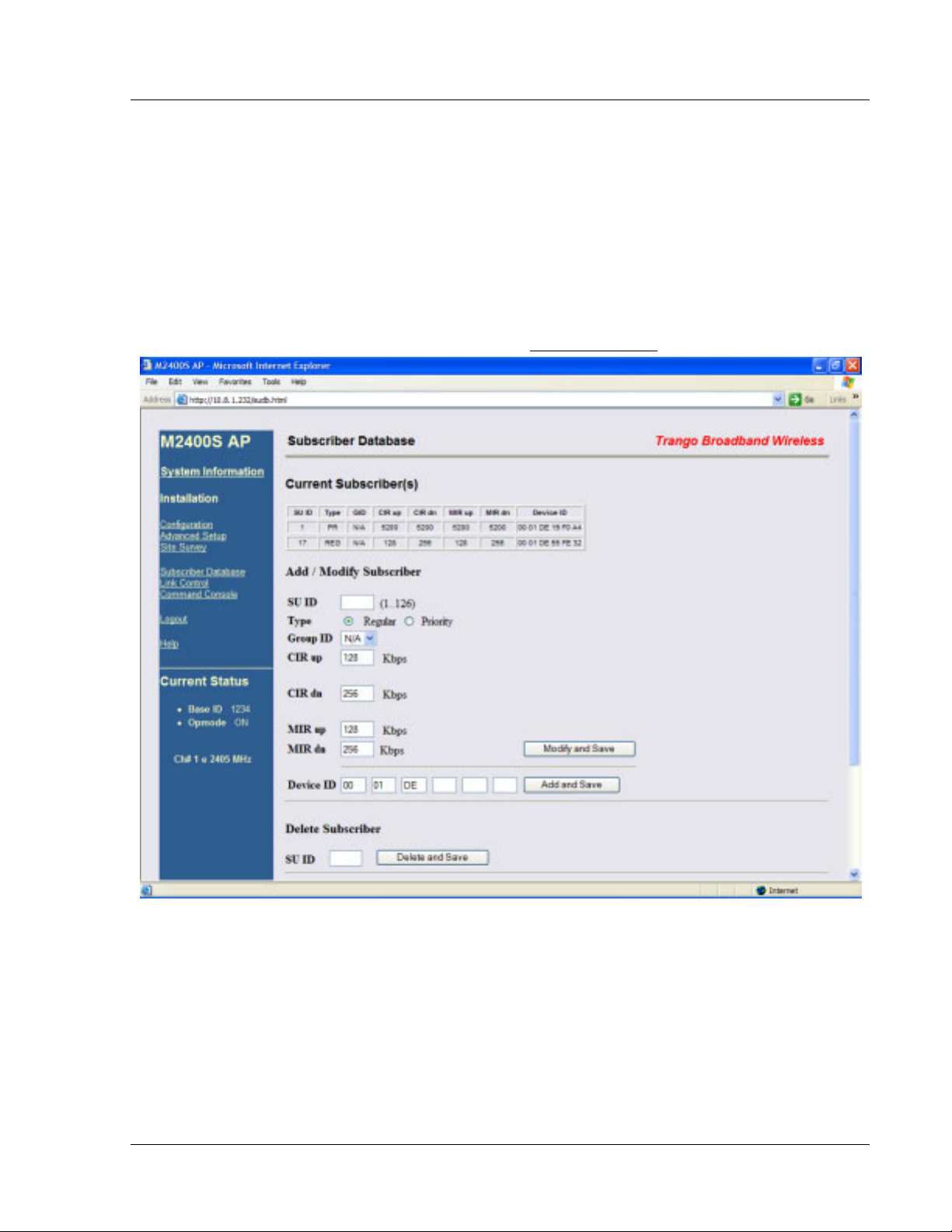
Prior to establishing a wireless link, the user must configure the SUDB in the AP with each SU’s MAC address and
related settings. The SUDB includes information about each SU. Click on the Subscriber Database
modify, or delete SUs. The key information for each SU includes the following:
SU ID: User definable Subscriber Unit ID (1…126)
TYPE: PR (Priority) or REG (Regular). Priority SUs are polled more frequently than regular SUs.
Priority SUs will generally respond to the AP with less latency than regular SUs.
Group: SU to SU Group # (1..F in hex) for SU to SU communications within the same sector. Note:
This SU to SU feature allows interconnectivity between multiple SUs in the same sector,
without the need for a router. Only SUs with same SU to SU group # may communicate with
each another. If you do not want the SUs to communicate with each other, choose N/A for
SU to SU group. In order to use SU to SU communication, AP switch #3 must be ON.
Default setting for switch #3 is OFF.
! Note: SUs using SU to SU communication must be on the same subnet.
CIR UP: Committed Information Rate from SU to AP. Minimum upstream rate (measured in Kbps) at
which the SU will attempt to deliver bandwidth to the AP. Maximum setting is 5200.
Trango Broadband Wireless — User Manual M2400S Rev A
page to add,
Page
11
Page 16
Basic Configuration via Browser Interface
CIR DOWN: Committed Information Rate from AP to SU. Minimum downstream rate (measured in Kbps)
at which the AP will attempt to deliver bandwidth to that SU. Maximum setting is 5200.
MIR UP: Maximum Information Rate from SU to AP. Maximum upstream rate (measured in Kbps) at
which the SU will attempt to deliver bandwidth to the AP. Maximum setting is 5200.
MIR DOWN: Maximum Information Rate from AP to SU. Maximum rate (measured in Kbps) at which the
AP will attempt to deliver bandwidth to that SU. Maximum setting is 5200.
DEVICE ID: MAC address of the SU.
Creating an SU in the SUDB
1. Connect to the AP (see Getting Started) and open the Subscriber Database page.
2. Enter the SU ID (range 1 – 126).
3. Select either PRIORITY or REGULAR.
4. If the SU will be part of an SU to SU group, enter the SU to SU group number.
5. CIR up (SU to AP Committed Information Rate) is the minimum upstream bandwidth for the SU in Kbps.
6. CIR dn (AP to SU Committed Information Rate) is the minimum downstream bandwidth for the SU in
Kbps.
7. MIR up (SU to AP Maximum Information Rate) is the maximum upstream bandwidth for the SU in Kbps.
8. MIR dn (AP to SU Maximum Information Rate) is the maximum downstream bandwidth for the SU in
Kbps.
Trango Broadband Wireless — User Manual M2400S Rev A
Page
12
Page 17

Basic Configuration via Browser Interface
9. Enter the Device ID (MAC Address of the SU).
10. Save and Activate changes.
Important! Always remember to Save and Activate changes, otherwise the SUDB will revert back to its
!
previous state after a power cycle or reboot.
Important! SUs using SU to SU communication must be on the same subnet.
!
Configure Other Basic AP Parameters
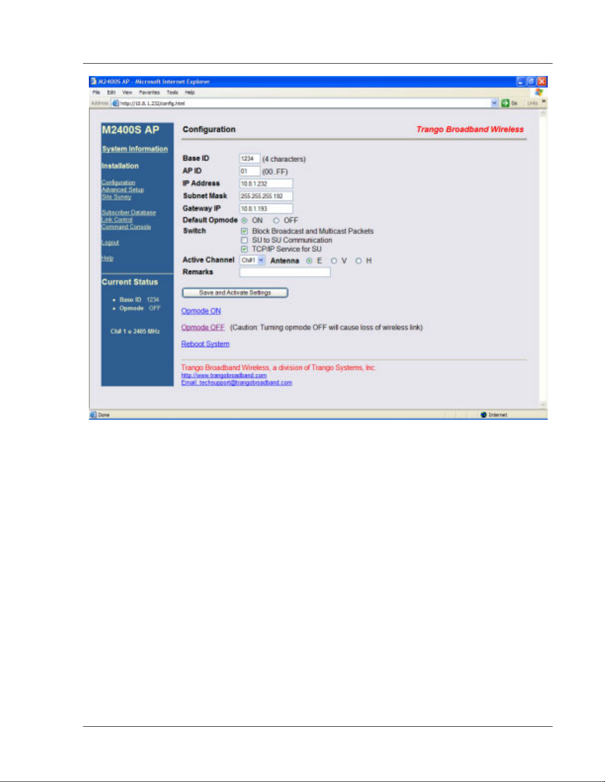
In addition to setting up the SU in the SUDB, the following settings from the AP’s Configuration page must be set
(or left at default).
Base ID: Base station ID, consisting of four user definable alphanumeric characters. Input of Base ID will
be in the format of xxxx. Where x is any character from the set : { 0..9; a..z; A..Z;
'!@#$%^&*()_+[]\<>,./?' } . The Base ID is typically assigned to a single AP or a group of APs at
a particular cell site. The Base ID in the AP must match the Base ID in the SU in order for a link to
be established. This parameter can only be changed while in Opmode "OFF."
AP ID: User definable AP ID (00-FF). Default is last two digits of MAC ID. Once authenticated, the AP
will automatically assign its AP ID to the SU. This parameter can only be changed while in
Opmode “OFF.”
IP Address, Subnet Mask, and Gateway:
The IP address used on the radio is for management purposes only. Since this is a layer-II device,
these parameters do not play a role in establishing the wireless link.
Default Opmode:
Will initiate Operation Mode of the radio after a power cycle or reboot. When the radio enters
Opmode "ON," it will be transmitting. When the radio enters Opmode "OFF," it will not be
transmitting. The radio can be put into Opmode "OFF" regardless of its default Opmode by
telnetting into the radio within the first 30 seconds after a power cycle or reboot.
Active Channel/Polarization:
Is the current channel and antenna polarization of the unit when in Opmode "ON."
To configure the AP’s other basic settings, complete the following steps:
1. Connect to the AP (see Getting Started) and open the Configuration
page.
Trango Broadband Wireless — User Manual M2400S Rev A
Page
13
Page 18
Basic Configuration via Browser Interface
2. Set Base ID, or choose default base ID of 0000 (must match the SU).
3. Set AP ID (00-FF HEX).
4. Set IP, Subnet, and Gateway, or leave at default settings. Keep in mind if you change the IP Settings of
the radio you will loose your HTTP session when you save and activate.
5. Choose Active Channel (1-8).
6. Choose Antenna Polarization (H or V) or choose E for an external antenna.
7. Ensure default Opmode is "ON."
8. Save and Activate Settings.
9. If this is the first SU to be added to the SUDB, reboot the AP.
After reboot, the AP will automatically enter its default Opmode, after approximately 40 seconds. At this time it
will begin actively searching for all SUs in its SUDB. Once an active SU is detected, the authentication and
association process will begin.
Trango Broadband Wireless — User Manual M2400S Rev A
Page
14
Page 19
Basic Configuration via Browser Interface
Configure Basic SU Parameters
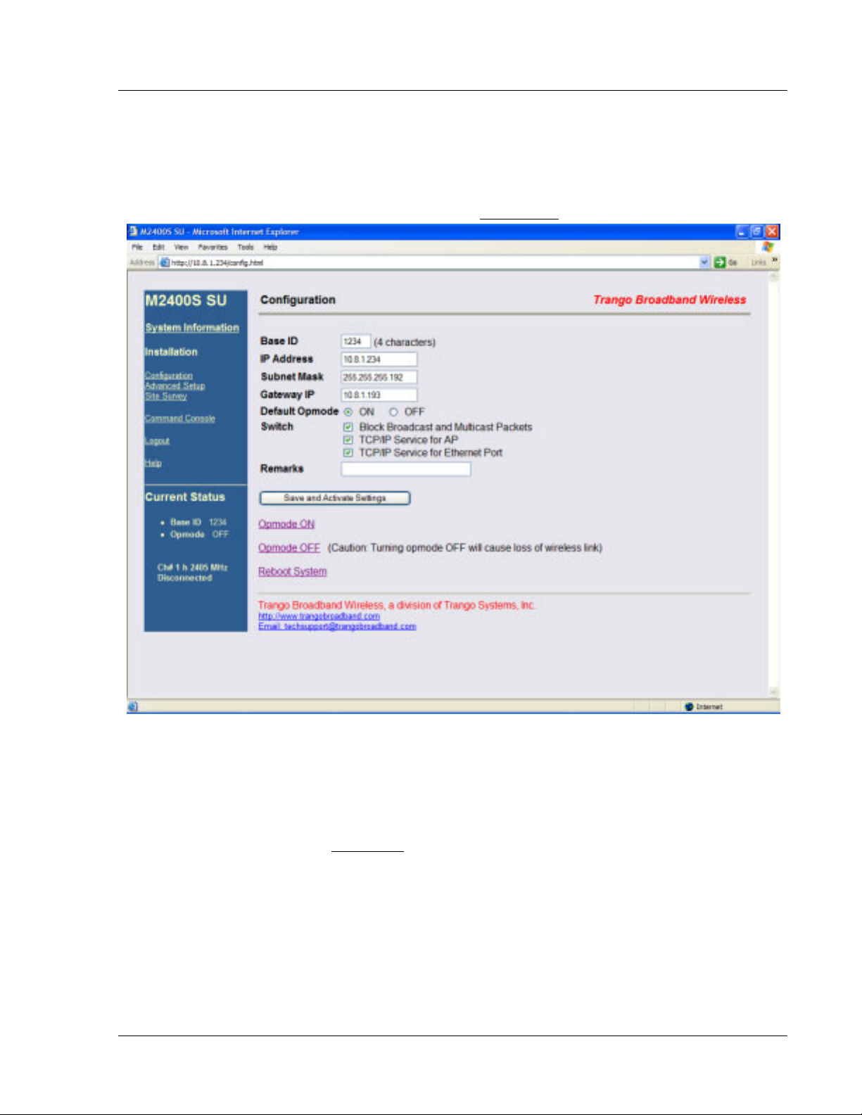
In order to establish a working link, the Base ID in the SU must match the Base ID of the AP.
SU Basic Setup:
1. Connect to the SU (see Getting Started) and open the Configuration page.
2. Set Base ID (must match the AP).
3. Set IP, subnet, and gateway, or leave at default settings. Keep in mind if you change the IP Settings of the
radio you will loose your HTTP session when you save and activate.
4. Ensure default Opmode is "ON."
5. Save and Activate Settings.
6. If Opmode is “OFF,” click Opmode ON
At this point, if all parameters have been set correctly and the radios are within range, a wireless link between the AP and
SU will automatically become established. Once this occurs the SU will be in “associated” status.
Allow approximately 60 seconds for the radios to complete the boot-up cycle and to associate. If the AP is busy
servicing many SUs, the association process may take slightly longer.
Trango Broadband Wireless — User Manual M2400S Rev A
.
15
Page
Page 20
Basic Configuration via Browser Interface
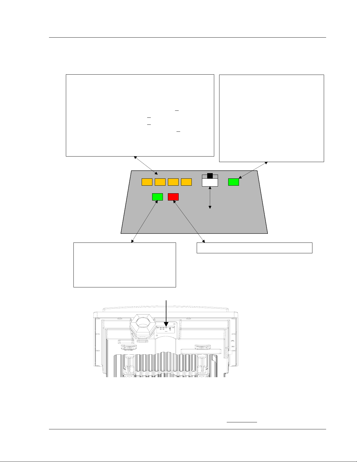
LED Summary
At this point it is useful to learn about the various LEDs that can be found on the bottom of the radio. These LEDs
can assist the user in determining radio and link status.
RSSI LEDs (YELLOW) - In all modes except "Survey,"
the unit's four yellow LEDs indicate the level of RF
signal being received from a valid AP.
Yellow LED 1 (rightmost): On when RSSI > -85 dBm
Yellow LED 2 : On when RSSI > -75 dBm
Yellow LED 3 : On when RSSI > -65 dBm
Yellow LED 4 (leftmmost): On when RSSI > -55 dBm.
In addition, these 4 LEDs will flash once to indicate the
'factory reset' button has been activated.
10/100 Link LED (GREEN) Illuminated when link speed is
negotiated at 100 BaseT. It is off
when link speed is 10 BaseT or not
connected.
LED / RESET BUTTON WINDOW
ASSOCIATION LED (GREEN)
Blinking once every second in
Opmode "OFF" (AP and SU).
Twice per second Opmode "ON" and
scanning for an AP (SU Only).
Solid after unit is associated with an
AP (SU Only).
Solid after unit is in Opmode "ON" (AP
Only).
RESET BUTTON - resets IP and
password to factory default
ACT LED (RED) - Ethernet Activity Light
Figure 7: LED Summary
Link Control Page
The radio’s firmware includes several useful tools to assist in determining which SUs are associated, and the
quality of each link. One method for verifying link quality is by using the Link Control
Trango Broadband Wireless — User Manual M2400S Rev A
page.
Page
16
Page 21
Basic Configuration via Browser Interface
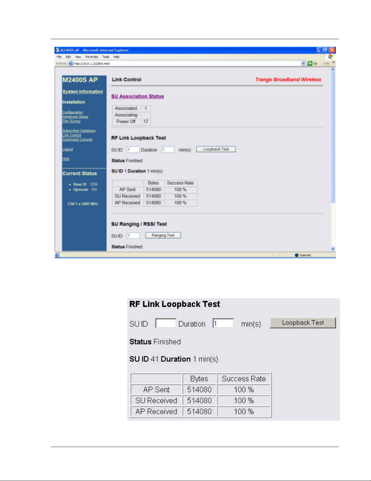
On this page the user can immediately see which SUs are currently associated. In the page shown, SU ID# 1 is
associated, and SU ID# 17 is not. Consider "Power Off" status synonymous with "not associated."
RF Link
Loopback Test
The RF Link Loopback
Test is one of the built-in
tools for evaluating the
quality of the wireless link.
Specify an SU ID and time
in minutes to conduct the
test. The test is prioritized,
so it will take precedence
over all other traffic. 1600
byte packets are sent and
received between the SU
and AP at 50 millisecond
intervals over the time
specified.
Trango Broadband Wireless — User Manual M2400S Rev A
Page
17
Page 22
Basic Configuration via Browser Interface
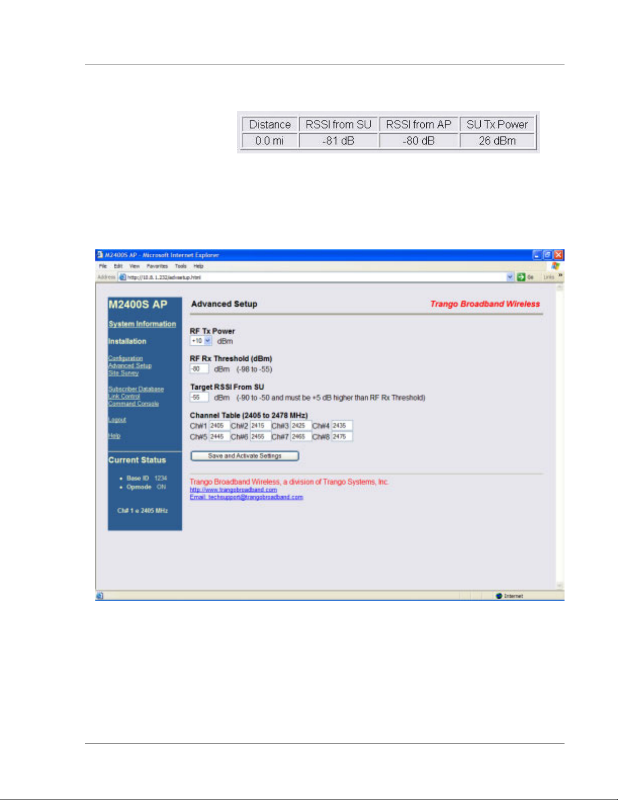
SU Ranging Test
This test reports the SUs distance
from AP in miles, received signal
strength for uplink and downlink,
and SU TX Power. Use a link budget calculator to analyze results. Significant differences between calculated and
actual values could indicate alignment or LOS issues!
Advanced Setup Page
The advanced set up page includes several important parameters including RF TX Power, RF RX Threshold,
target RSSI from SU (AP only), and Channel Table.
RF TX Power: Sets the conducted RF power output of the radio. Highest allowable setting is +23 dBm.
Lowest setting is +10 dBm. This value does not include antenna gain.
RF RX Threshold: Sets the receive threshold of the radio. The radio will not process signals received below
this level, so it is very useful for interference mitigation. For a smaller radius of
operation, use a higher threshold (-75 is higher than -80).
Target RSSI from SU: Used by the powerleveling process to automatically adjust the RF output power level of
all SUs in a sector so the signal strength from each SU, as measured at the AP, will be
roughly equal.
Trango Broadband Wireless — User Manual M2400S Rev A
Page
18
Page 23
Basic Configuration via Browser Interface
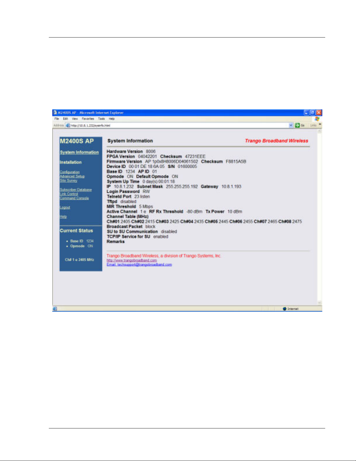
Channel Table: Assigns channel numbers to actual frequencies of operation. Default settings allow the
largest number of channels (8) within the band, while still maintaining a 10 MHz channel
spacing.
Other Key Parameters
This section describes the remainder of the parameters listed on the System Information page. Most of these
parameters are the same for both APs and SUs.
Hardware Version: Hardware version is factory-set and can not be changed by the user.
FPGA Version: Low level field programmable gate array firmware currently loaded on the radio. Normally the
FPGA firmware will not require upgrading.
Firmware Version: Main firmware. In this example, the version part of the string is 1p0 (v1.0), the hardware
code is H8006, and the remainder of the string is a date code.
Device ID: MAC address of the radio.
S/N: Serial number of the radio.
Telnetd Port: User changeable telnet port of radio.
TFTPd: Current status of TFTP daemon. Used for uploading firmware.
MIR Threshold: Shown in Mbps (0..5) Maximum Information Rate (MIR) Threshold. The MIR Threshold is the
aggregate throughput of the AP at which the AP will start to enforce CIR rules for the SUs.
Trango Broadband Wireless — User Manual M2400S Rev A
Page
19
Page 24
Basic Configuration via Browser Interface
Active Channel: The channel currently being used by the radio.
RFRX Threshold: Sets the receive threshold of the radio. The radio will not process signals received below this
level, so it is very useful for interference mitigation. For a smaller radius of operation use a higher threshold (-65 is
higher than -70).
Broadcast Packet: This software switch (0) enables/disables the blocking of Ethernet control packets, except
ICMP and ARP, to reduce the amount of unnecessary overhead introduced into the wireless link.
SU to SU Communication: If enabled (switch 3), SUs with matching SU to SU groups (except group 0) can
communicate in peer-to-peer mode through the AP without the need of a router behind the AP. SUs using SU to
SU communication must be on the same subnet.
TCP/IP Service for SU: If enabled, the AP can be accessed via TCP/IP (Telnet or HTTP) from the SU side of the
network via the wireless link.
Remarks: User definable radio information (i.e. customer name, address of installation, etc). A maximum of 28
characters can be stored.
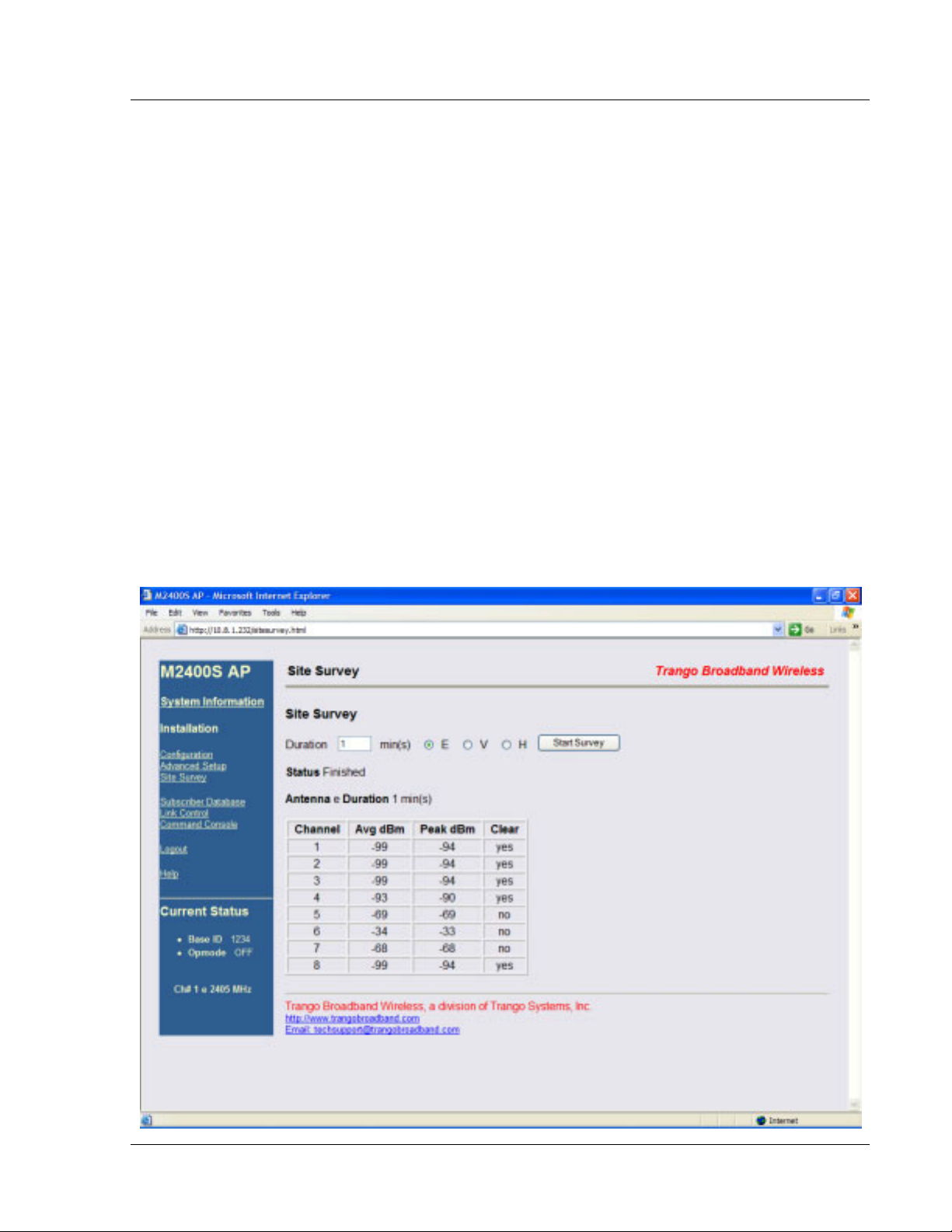
Site Survey Page
The Site Survey page provides a useful tool for detecting and measuring interference. The radio must be in
Opmode “OFF” in order to use this feature.
Enter the number of minutes desired for the survey, and select the polarization H, V, or E (for an external antenna).
Click "Start Survey." A survey of the default 8 channels will be performed. Results are reported in dBm per
channel as average and peak. A channel is reported to be "Clear" if the peak and average are below the RF RX
Threshold by more than 8 dB.
Trango Broadband Wireless — User Manual M2400S Rev A
Page
20
Page 25

Basic Configuration via CLI
Section 5 Basic Configuration via CLI
This section covers how to utilize the radio’s CLI interface to establish a working wireless link.
In this section, the most common settings using the CLI are discussed. Topics include:
• Access Point Basic Settings
• Subscriber Unit Database Settings
• Subscriber Unit Basic Settings
See Appendix A − Command Set Reference, for a complete listing of CLI commands.
See the “Getting Started” section for a description of how to access the radio using the telnet interface.
Access Point Basic Settings
After logging onto an AP or SU, it is good practice to type the sysinfo command to see the radio’s basic system
information. Example (Access Point):
#> sysinfo
[Hardware Version] 8006
[FPGA Version] 04042201 [Checksum] 47231EEE
[Firmware Version] AP 1p0x8H8006D04061502 [Checksum] F8815A5B
[Device ID] 00 01 DE 18 6A 05 [S/N] 01600005
[Base ID] 1234 [AP ID] 01
[System Up Time] 0 day(s) 01:37:29
[Opmode] on [Default Opmode] on
[IP] 10.8.1.232 [Subnet Mask] 255.255.255.192 [Gateway] 10.8.1.193
[Login Password] RW
[Httpd Port] 80 [Httpd Status] listen
[Telnetd Port] 23 [Telnetd Status] connected (10.8.0.60,1454)
[Tftpd] disabled
[RF Tx Power] 10 dBm
[RF Rx Threshold] -80 dBm
[MIR Threshold] 5 Mbps
[Ch#01] 2405 Mhz [Ch#02] 2415 Mhz [Ch#03] 2425 Mhz [Ch#04] 2435 Mhz
[Ch#05] 2445 Mhz [Ch#06] 2455 Mhz [Ch#07] 2465 Mhz [Ch#08] 2475 Mhz
[Default Channel] 1 e [Active Channel] 1 e
[Broadcast Packet] block [SU to SU] off [TCP/IP for SU] on
[Remarks]
[RF Rx] 0 kbps [RF Tx] 0 kbps [Eth Rx] 3 kbps [Eth Tx] 5 kbps
Many of these parameters can be changed by the user. A description of each of these changeable parameters, along
with the related command is shown in the table below.
Important! When changing settings, it is usually necessary to type the save ss command in order to update
!
the radio’s flash memory. If you do not type the save ss command, the setting will be lost the next time the
radio is rebooted or power cycled.
.
AP SYSTEM INFORMATION PARAMETERS AND RELATED COMMANDS
AP Parameter Description Related CLI Command
Device ID MAC Address of AP N/A
Base ID Specifies the cell or cluster to
which the AP belongs. Base ID
must match in AP and SU in
order to establish a wireless
link.
set baseid <baseid>
Example:
#>set baseid aa12
Trango Broadband Wireless — User Manual M2400S Rev A
Page
21
Page 26

Basic Configuration via CLI
AP SYSTEM INFORMATION PARAMETERS AND RELATED COMMANDS
AP Parameter Description Related CLI Command
AP ID This parameter provides a
unique number for each AP. If
Target AP is specified on SU,
the SU can only authenticate
with the specified AP. The
default AP ID is the last two
bytes of the MAC address.
Opmode Current Opmode of the radio.
Default Opmode Determines the Opmode (“ON”
or “OFF”) of the radio after
reboot/power cycle. When this
parameter is set to “ON,” the
radio will progress into
Opmode “ON” automatically
after a reboot/power cycle.
Opmode Start Determines the amount of time
the radio will remain in
Opmode “OFF” after
reboot/power cycle before
progressing to the default
Opmode.
IP
Subnet
IP, Subnet, and Gateway
address of the radio.
Gateway
TFTPD Status TFTPD status (on or off).
TFTPD should be turned on to
import a file into the radio
(such as new firmware).
Default is off. TFTPD will
revert to Off after rebooting.
set apid <apid> (00-FF in HEX)
Example:
#>set apid 33
opmode on y
This sets the radio to Opmode “ON.” If the radio is
accessed via the Ethernet port within the first 30
seconds after reboot/power cycle, the Opmode will
default to “OFF.”
set defaultopmode <on or off>
Example:
#>set defaultopmode on
set defaultopmode on [<time (sec)>]
Example:
#>set defaultopmode on 60
ipconfig [<new ip> <new subnet mask> <new
gateway>]
Example:
#>ipconfig 10.1.1.2 255.0.0.0 10.1.1.1
tftpd [<on|off>]
Example:
#>tftpd on
Trango Broadband Wireless — User Manual M2400S Rev A
Page
22
Page 27

Basic Configuration via CLI
AP SYSTEM INFORMATION PARAMETERS AND RELATED COMMANDS
AP Parameter Description Related CLI Command
MIR Threshold (Kbps) User specified MIR Threshold.
To specify total throughput
level that the AP will serve only
CIR (committed information
rate) to associated SUs.
When MIR Threshold is
disabled, the AP will serve MIR
for all its SUs.
When MIR Threshold is
activated, and the network
traffic exceeds the MIR
Threshold, the AP will only
serve CIR for all its SUs.
When MIR Threshold is
activated, and the network
traffic does NOT exceed the
MIR Threshold, the AP will
still serve MIR for all its SUs.
Active Channel Current RF channel
Antenna Current antenna selection:
(h)horizontal, (v)vertical,
(e)external
RF RX Threshold Specifies the receiver
sensitivity of the AP. It is a
powerful tool when the radio is
in a noisy environment. AP
will block out any signal
received which is below the RF
Rx threshold. Separate settings
exist for both ISM and UNII
bands.
RF TX Power Current transmit power of the
AP not including antenna gain.
Channel Table Assigned frequencies to
channels. All channels may be
re-assigned as desired by the
administrator.
Broadcast Packet Filter This software switch (0)
enables/disables the blocking of
Ethernet control packets, except
ICMP and ARP, to reduce the
amount of unnecessary
overhead introduced to the
wireless link.
SU to SU This software switch (3)
enables/disables the SU to SU
feature. When SU to SU is
turned on, multiple SU’s within
mirth [<0..3, Mbps>]
Example:
#>mirth 2
freq [<ch#> <v|h>]
Example:
#>freq 3
This command will change the channel of the AP to
3.
antenna [<v|h|e>]
rfrxth <-90|-85|-80|-75|-70|-65>
example:
#>rfrxth –70
power <set> <min|max|<dBm>
Example:
#>power set 10
freq writechannel [<ch#> <freq>]
Example:
#>freg writechannel 3 910
This command will change channel 3 to 910 Mhz.
sw 0 [<on|off>] (default is on)
Example:
#>sw 0 on
note: All switch settings (0-7) are set using the sw #
[<on/off>] command.
sw 3 [<on|off>] (default is off)
Example:
#>sw 3 on
Trango Broadband Wireless — User Manual M2400S Rev A
Page
23
Page 28

Basic Configuration via CLI
AP SYSTEM INFORMATION PARAMETERS AND RELATED COMMANDS
AP Parameter Description Related CLI Command
the same sector (meaning
associated to that AP) can
communicate with each other,
provided they have the same
SU2SU group number.
TCP/IP for SU This software switch (7) when
on, allows users on the SU side
of the network to telnet or
HTTP into the AP.
Remarks User definable radio
information (i.e. customer
name, address of installation,
sw 7 [<on|off>] (default is on)
Example:
#>sw 7 off
remarks [<remarks>]
Example:
#>remarks 123 Elm Street
and so on). A maximum of 28
characters can be stored.
Subscriber Unit Database Settings
Once you are familiar with the basic system information presented above, you are ready to add one or more SUs to
the SUDB. There are five basic commands related to the SUDB: sudb add, sudb cirmir, sudb defaultcirmir, sudb
view, and save sudb.
Adding an SU
You will need to know the following information to add an SU to the database:
1. MAC ID of the SU (printed on the back of the SU).
2. Polling priority: either PRIORITY or REGULAR.
! Note: SUs designated as PRIORITY will get polled more often by the AP.
To add an SU to the SUDB, use the following command and syntax:
sudb add <suid> <pr|reg> <device id>
suid: SU ID
pr: priority user
reg: regular user
<device id>: xx xx xx xx xx xx in hexadecimal (this is the MAC address of the SU)
Example:
#>sudb add 5 pr F3 3C 50 67 89 D4
In this example, SU ID 5 was added as a Priority SU. The MAC ID of that SU is F3 3C 50 67 89 D4.
! Note: You can add up to 126 entries in the SUDB
CIR / MIR Commands
The default CIR/MIR setting is 5000 Kbps for upstream and downstream values.
To change SU’s CIR/MIR settings, use the following command:
sudb cirmir <suid | all> <cir dn> <cir up> <mir dn> <mir up>
Example:
#>sudb cirmir 5 128 256 5000 5000
Trango Broadband Wireless — User Manual M2400S Rev A
Page
24
Page 29

Basic Configuration via CLI
In this example, SU #5’s CIR downstream is set to 128 and CIR upstream is set to 256. MIR upstream and
downstream are set to 5000.
To change the default CIR/MIR values, use the following command:
sudb defaultcirmir <default cir dn> <default cir up> <default mir dn> <default mir up>
Example:
#>sudb defaultcirmir 256 256 512 512
To view the entries in the SUDB, type the command sudb view.
To save the changes you have made to the SUDB, type save sudb
Other important SUDB related commands are sudb delete, sudb gid, and sudb modify. See Appendix A for
descriptions of these commands.
Important! After updating the SUDB, type the command save sudb to save the SUDB. If you do not save the
!
SUDB file will revert back to its previous state after power cycle or reboot.
Important! SUs using SU to SU communication must be on the same subnet.
!
Subscriber Unit Basic Settings
Once logged into the SU, you can receive a comprehensive snapshot of the system’s configuration info and status
by typing the command sysinfo.
#> sysinfo
[Hardware Version] 0006
[FPGA Version] 04042201 [Checksum] 47231EEE
[Firmware Version] SU 1p0x8H0006D04061502 [Checksum] 6DDF232C
[Device ID] 00 01 DE 19 F0 A4 [S/N] 01700004
[Base ID] 1234 [AP ID] 01 [SU ID] 1
[System Up Time] 0 day(s) 05:14:51
[Opmode] on [Default Opmode] on
[IP] 10.8.1.234 [Subnet Mask] 255.255.255.192 [Gateway] 10.8.1.193
[Login Password] RW
[Httpd Port] 80 [Httpd Status] listen
[Telnetd Port] 23 [Telnetd Status] connected (10.8.0.60,1738)
[Tftpd] disabled
'[RF Tx Power] 22 dBm
[RF Rx Threshold] -98 dBm
[Ch#01] 2405 Mhz [Ch#02] 2415 Mhz [Ch#03] 2425 Mhz [Ch#04] 2435 Mhz
[Ch#05] 2445 Mhz [Ch#06] 2455 Mhz [Ch#07] 2465 Mhz [Ch#08] 2475 Mhz
[Default Channel] 1 h [Active Channel] 1 v [Associated] Y
[Broadcast Packet] block [Auto Scan AP] on [TCP/IP for AP] on [TCP/IP for Local
Eth] on
[Remarks]
[RF Rx] 3 kbps [RF Tx] 2 kbps [Eth Rx] 0 kbps [Eth Tx] 0 kbps
[ARQ RF Tx Retry] 0 [ARQ RF Tx Retry Maxed Out] 0
Many of these parameters can be changed by the user. A description of each of these changeable parameters, along
with the related command, is shown in the table below.
Trango Broadband Wireless — User Manual M2400S Rev A
Page
25
Page 30

Basic Configuration via CLI
Important! When changing settings, it is usually necessary to type the save ss command in order to update
!
the radio’s flash memory. If you do not type the save ss command, the setting will be lost the next time the
radio is rebooted or power cycled.
SU SYSTEM INFORMATION PARAMETERS AND RELATED COMMANDS
SU Parameter Description Related CLI Command
Device ID MAC Address of the SU N/A
Base ID Specifies the cell or cluster to
which the SU belongs.
Target AP If unique AP ID selected, the
SU can only associate with
the specified AP. If ALL is
selected, the SU can
associate with any AP with a
matching BASE ID.
Opmode Current Opmode of radio. opmode on y - set Opmode to “ON.” (note: “y”
Default Opmode Determines the Opmode
(“ON” or “OFF”) of the radio
after reboot/power cycle.
When this parameter is set to
“ON,” the radio will progress
into Opmode “ON”
automatically after
reboot/power cycle.
IP
Subnet
IP, Subnet, and Gateway
address of radio.
Gateway
set baseid <baseid>
Example:
#>Set baseid aa12
targetap <apid>
Examples:
#>targetap 33
#>targetap all
is necessary if default Opmode is “OFF.”)
opmode off – set Opmode to “OFF.”
set defaultopmode <on or off>
Example:
#>set defaultopmode on
ipconfig [<new ip> <new subnet mask> <new
gateway>]
Example:
#>ipconfig 10.1.1.3 255.0.0.0 10.1.1.1
TFTPD TFTPD status (on or off).
TFTPD should be turned on
to import a file into the radio
(such as new firmware).
Default is off. TFTPD will
revert to off after
reboot/power cycle.
RF TX Power Current transmit power of the
SU not including antenna
gain. This is controlled by
the AP.
Active Channel Shows the channel used in
the current association, and
"Associated" or
"Disconnected" depending
on the association status.
Trango Broadband Wireless — User Manual M2400S Rev A
tftpd [<on|off>]
Example:
#>tftpd on
Informational Parameter – can not be manually
changed by user.
If Autoscan AP (SW 1) is on, the active channel
(and antenna selection) will be set once the SU
scans and begins the association process with an
AP.
If Autoscan AP is off, the active channel is set by
the user, using the freq command.
freq [<ch#> <v|h>]
Example:
Page
26
Page 31

Basic Configuration via CLI
SU SYSTEM INFORMATION PARAMETERS AND RELATED COMMANDS
SU Parameter Description Related CLI Command
#>freq 3
This command will change the channel of the AP to
3. Use the antenna command to select an antenna
polarization.
antenna [<h | v |e>]
Broadcast Packet Filter This software switch (0)
enables/disables the blocking
of Ethernet control packets,
except ICMP and ARP, to
reduce the amount of
unnecessary overhead
introduced into the wireless
link. Default setting is ON.
AP Autoscan This software switch (1) is to
turn AP autoscan on or off.
TCP/IP for AP This software switch (2)
when on, allows users at the
AP side of the network to
telnet or HTTP into the SU.
TCP/IP for Local
Ethernet Port
This software switch (6)
when on, allows users on the
wired side of the SU to telnet
or HTTP into the SU
regardless of the Opmode.
Remarks User definable radio
information (i.e. customer
name, address of installation,
and so on). A maximum of
28 characters can be stored.
Counters:
RF TX RF RX
Eth TX Eth RX
This is an average of wired
and wireless, transmitted and
received, traffic in kilobits
per second.
sw 0 [<on|off>]
Example:
#>sw 0 on
sw 1 [<on|off>] (default is on)
sw 2 [<on|off>] (default is on)
Example:
#>sw 2 off
sw 6 [<on|off>] (default is on)
remarks [<remarks>]
Example:
#>remarks 678 Oak Ave
Informational Parameter
Trango Broadband Wireless — User Manual M2400S Rev A
Page
27
Page 32

Mounting Hardware
)
Section 6 Mounting Hardware
1
2
3
4
Not Supplied
5
ITEM
NO.
1
Radio
2 5/16 x 3" Threaded Rod 4
3 5/16 Keps Nut 8
4 "V" Bracket 2
5
Mono Pod Mount (Not Supplied
PART NUMBER
QTY.
1
1
Figure 8: M2400S Mounting Hardware Assembly
Up/Down Tilt
4X Must Be loo sene d fo r
Up/Down Tilt
Figure 9: Articulation for M2400S with Mono Pod Mount (not supplied)
Trango Broadband Wireless — User Manual M2400S Rev A
Page
28
Page 33
Mounting Hardware
Cabling and Grounding Considerations
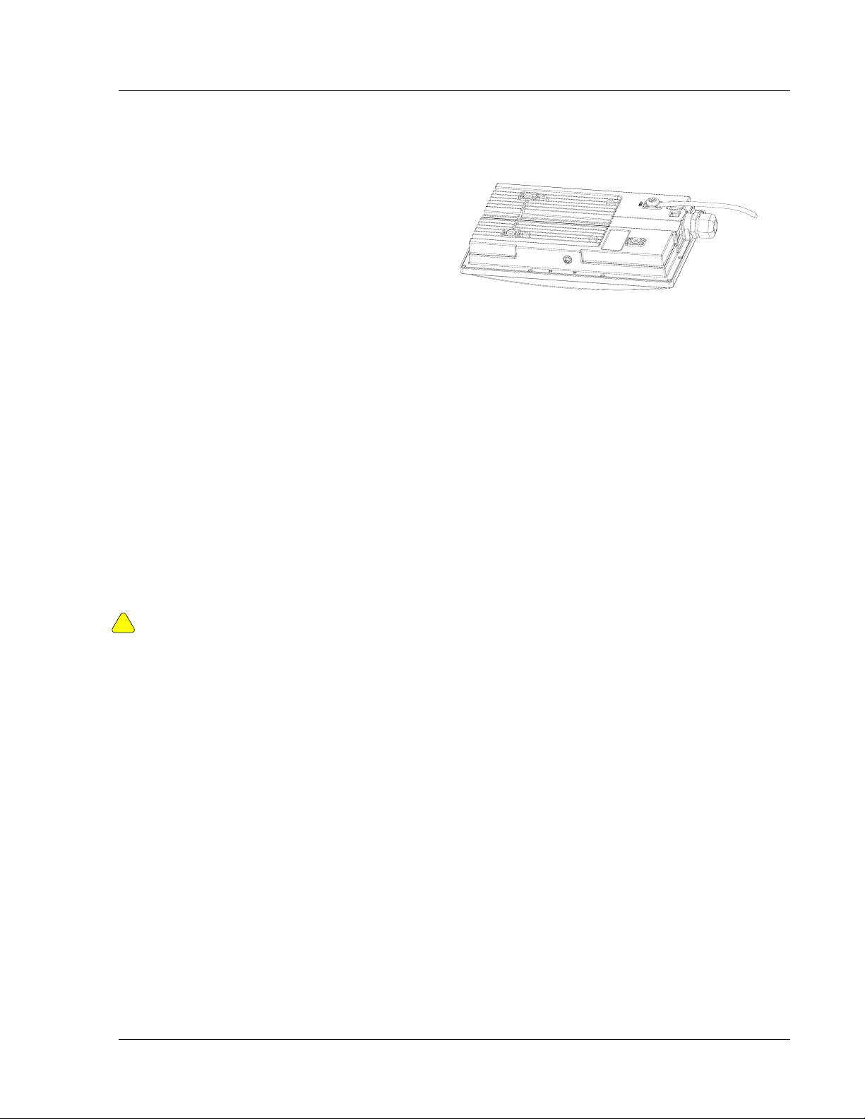
Grounding Example
Proper mounting of the radio includes
consideration for grounding. Please note that if
the radio is attached to a metal pole that is
earth-grounded, no other grounding is
necessary. If the radio is not earth-grounded
via the mounting bracket, you must attach a
grounding wire to the grounding stud on the
back of the radio as in the adjacent diagram.
Installation Notes
Access to the radio’s RJ-45 Port and LED status lights are purposely located at the bottom of the radio to minimize the risk of
water intrusion. Do not mount the radio upside down.
The J-Box is not a weatherized device and must be located either indoors or in a weather-protected cabinet.
Shielded twisted pair Cat-5 cable is recommended for all installations unless cable is placed in metal conduit.
The shield within the Cat-5 cable does not need to be grounded if the radio itself is grounded.
It is important to consider that most Cat-5 cable will deteriorate over time if exposed to the weather (especially direct
sunlight). Conduit (metal or PVC) is recommended to protect the cable.
!
It is important to provide strain relief and drip loop for STP Cat-5 cables. Do not mount the radio upside down.
Figure 10: Grounding of Radio
Important! The Ethernet port compression washer should be loosely tightened around the Cat-5 cable
to allow pressure equalization within the radio enclosure. Leave approximately 1 mm around the Cat-5.
Trango Broadband Wireless — User Manual M2400S Rev A
Page
29
Page 34

Deployment
Section 7 Deployment
Once you are familiar with the basic operation of the radios, you are ready for deployment in the field. The deployment
process consists of the following steps:
• Site Selection
• Site Survey
• Channel Planning
• SU Antenna Alignment
• Link Management Commands
Site Selection
Proper site selection for your AP will help ensure a successful deployment. Site selection will depend on a wide variety
of factors, but from the radio’s performance standpoint consider the following:
• Path from AP to SU should provide as few obstructions as possible. It is advisable to place the AP as high as
possible on a tall building or tower.
• Ethernet cable is limited to 300 feet from Ethernet device (router, switch) to radio.
• Radios require grounding for optimal performance.
• AP provides sector coverage of 60 degrees azimuth and 18 degrees elevation
• Consider nearby sources of interference that could degrade performance of radio. Mount radios as far from
sources of interference as possible.
• Perform a site survey to determine noise levels and the relative clarity of channels at the chosen installation
location.
Site Survey
Both the AP and SU provide a powerful on-board site survey tool. This tool will tell you if there is interference present in
the 2.4 GHz ISM band.
Command: survey <time> <antenna>
In order to use the survey command, the radio must be in Opmode “OFF.” The survey can be performed for up to 10
seconds per channel (incrementing by 5 MHz). The test can be run for either the (h) horizontal polarization, (v) vertical
polarization, or (e) external antenna.
Prior to performing the site survey, place the radio in the installation spot, and aim the radio in the desired direction.
The results of the test will provide you with a listing of each channel in the band, the average signal received, and the
maximum signal received during the survey period.
In general you will be looking for frequencies with interference signal strength of –85 dBm or lower. If interference is
present on various channels, it is recommended that you chose clean channels or alternate polarizations for your
deployment. If it is not possible to use a clean channel/polarization combination, there are various methods available to
mitigate the affects of interference. These methods include the use of the RFRX THRESHOLD settings, the use of
external shields, and/or external narrower beam antennas.
Trango Broadband Wireless — User Manual M2400S Rev A
Page
30
Page 35

Deployment
Site Survey Example:
#> survey 2 v
Press [space] then [enter] to stop
2350 MHz peak -94 dBm avg -99 dBm
2355 MHz peak -94 dBm avg -99 dBm
2360 MHz peak -94 dBm avg -99 dBm
2365 MHz peak -94 dBm avg -99 dBm
2370 MHz peak -94 dBm avg -99 dBm
2375 MHz peak -94 dBm avg -99 dBm
2380 MHz peak -94 dBm avg -99 dBm
2385 MHz peak -94 dBm avg -99 dBm
2390 MHz peak -94 dBm avg -99 dBm
2395 MHz peak -94 dBm avg -99 dBm
2400 MHz peak -94 dBm avg -99 dBm
2405 MHz Ch 1 peak -91 dBm avg -92 dBm
2410 MHz peak -69 dBm avg -75 dBm **
2415 MHz Ch 2 peak -61 dBm avg -66 dBm ***
2420 MHz peak -70 dBm avg -76 dBm *
2425 MHz Ch 3 peak -90 dBm avg -92 dBm
2430 MHz peak -94 dBm avg -99 dBm
2435 MHz Ch 4 peak -94 dBm avg -99 dBm
2440 MHz peak -94 dBm avg -99 dBm
2445 MHz Ch 5 peak -94 dBm avg -99 dBm
2450 MHz peak -94 dBm avg -99 dBm
2455 MHz Ch 6 peak -94 dBm avg -99 dBm
2460 MHz peak -94 dBm avg -99 dBm
2465 MHz Ch 7 peak -94 dBm avg -99 dBm
2470 MHz peak -94 dBm avg -99 dBm
2475 MHz Ch 8 peak -94 dBm avg -99 dBm
2480 MHz peak -94 dBm avg -99 dBm
2485 MHz peak -94 dBm avg -99 dBm
2490 MHz peak -94 dBm avg -99 dBm
2495 MHz peak -94 dBm avg -99 dBm
2500 MHz peak -94 dBm avg -99 dBm
2505 MHz peak -94 dBm avg -99 dBm
2510 MHz peak -94 dBm avg -99 dBm
2515 MHz peak -94 dBm avg -99 dBm
2520 MHz peak -94 dBm avg -99 dBm
2525 MHz peak -94 dBm avg -99 dBm
2530 MHz peak -94 dBm avg -99 dBm
2535 MHz peak -94 dBm avg -99 dBm
2540 MHz peak -94 dBm avg -99 dBm
2545 MHz peak -94 dBm avg -99 dBm
2550 MHz peak -94 dBm avg -99 dBm
#>
Once the site survey is completed you are ready to install your radios. It is recommended that APs be installed first. The
reason for this is that the SU has a built-in RSSI tool that will help you properly aim the SU toward the AP to achieve the
maximum signal strength.
In this example of a survey
on the vertical polarization
for 2 seconds for each 5
MHz portion of spectrum,
the largest amount of
energy is detected at
frequency 2415 MHz.
The asterisks (****) indicate
the highest avg amount of
energy detected and
corresponds to the number
of yellow colored LEDs lit.
Note: The survey also
covers spectrum outside of
the operational range of the
radio.
AP Search and SU Antenna Alignment
Once the AP is installed and aligned in the correct general direction, it is time to install the SU. The hardware installation
of the SU is identical to the AP, including considerations for line-of-sight, cable distances, cable type, weather sealing,
and grounding.
Trango Broadband Wireless — User Manual M2400S Rev A
Page
31
Page 36

Deployment
Once the SU is installed and aimed in the general direction of the AP it is time to perform an RSSI (relative signal
strength indicator) test to determine the signal strength from the AP. Now you can precisely align the SU antenna for
maximum signal strength.
Although it is possible to rely upon the Subscriber Unit’s LEDs for alignment, more precise RSSI readings are available
from the command rssi.
In conjunction with the rssi command, it is also useful to perform the apsearch command. This command will tell you
which AP is providing an adequate signal at the location of the SU.
AP Search
1. Ensure AP is in Opmode “ON.”
2. Run the apsearch command to verify which AP is providing the strongest signal strength.
#> apsearch
Press [space] then [enter] to stop
1 2405 Hz 1234 DE 18 6A 05 [H: -55 dBm] [V: -75 dBm] [E: -99 dBm]
2 2415 Hz ---- FF FF FF FF [H: -98 dBm] [V: -98 dBm] [E: -99 dBm]
3 2425 Hz ---- FF FF FF FF [H: -99 dBm] [V: -99 dBm] [E: -99 dBm]
4 2435 Hz ---- FF FF FF FF [H: -99 dBm] [V: -98 dBm] [E: -99 dBm]
5 2445 Hz ---- FF FF FF FF [H: -99 dBm] [V: -98 dBm] [E: -98 dBm]
6 2455 Hz ---- FF FF FF FF [H: -99 dBm] [V: -99 dBm] [E: -99 dBm]
7 2465 Hz ---- FF FF FF FF [H: -99 dBm] [V: -99 dBm] [E: -99 dBm]
8 2475 Hz ---- FF FF FF FF [H: -99 dBm] [V: -99 dBm] [E: -99 dBm]
#>
RSSI Command for Antenna Alignment
In this example, an AP is detected on channel 1 with
polarization horizontal. Furthermore, the Base ID is 1234
and the MAC address is 00 01 DE 18 6A 05.
Step 1 Telnet into the SU (while in Opmode “OFF”). Use the freq and antenna command to note current radio settings.
Step 2 Run the rssi command. The telnet session screen will begin a continuous readout of the received signal strength.
As you read the RSSI reading, move the antenna in the horizontal and vertical planes until the maximum RSSI reading is
achieved. To allow for plenty of fade margin we recommend a continuous RSSI reading of -78 dBm or better. An RSSI
of –88 dBm will allow you to establish a wireless link, but there may not be sufficient fade margin for reliable and
continuous operation.
Example 1 has the wrong freq and antenna settings:
#> rssi
[ 1] peak -99 dBm avg -99 dBm
[ 2] peak -99 dBm avg -99 dBm
[ 3] peak -99 dBm avg -99 dBm
Example 2 has the correct freq and antenna settings:
#> rssi
[ 1] peak -38 dBm avg -80 dBm *
[ 2] peak -38 dBm avg -75 dBm **
[ 3] peak -37 dBm avg -75 dBm **
Step 3 If it is not possible to receive an adequate RSSI reading it may be necessary to reorient the AP (up/down,
left/right) to increase the output power. Or move the SU to a location with better line-of-sight to the AP. Alternatively
consider using external antennas on either the AP or SU or both.
Once you are satisfied with the RSSI reading, tighten down the SU in the optimum position. To stop the RSSI continuous
readout hit SPACE ENTER.
Trango Broadband Wireless — User Manual M2400S Rev A
Page
32
Page 37
Deployment
SU Alignment Using LEDs
The LED RSSI indicators on the bottom of the radio provide a handy alignment tool. If all four LEDs are lit, the unit is
receiving –64 dBm or stronger. If no LEDs are lit, there is not sufficient signal strength to establish a wireless link.
Lit LEDs Signal Strength
0 LED -86 dBm or weaker
1 LED -76 to -85 dBm
2 LED -69 to -75 dBm
3 LED -66 to -70 dBm
4 LED -65 dBm and stronger
Note: RSSI tool (telnet or LEDs) will show all RF energy on
a given freq. i.e. – a nearby SU on the same freq. passing
traffic may give the appearance of a strong signal from your
AP when in fact it is not and cause a misalignment.
Link Management Commands
Once the radios are properly aligned for maximum RSSI, ensure the SU’s default Opmode is “ON” and that all
configuration parameters are correct.
Reboot the SU. Once the SU enters Opmode “ON” the authentication process will begin, and the two radios will begin to
associate. From the AP side, there are several basic diagnostics commands, such as su ping, su info, and su testrflink,
which can check if a reliable RF link has been established. It may take one minute or more for the association process to
complete. This process may take longer if there are many SUs in the sector.
If all tests show favorable results, the wireless link will automatically begin passing Ethernet traffic between the
radios.
In establishing and diagnosing the quality of the link between AP and SU(s), there are a few commands that are especially
useful. All of these commands are performed at the AP. A summary of these commands follows:
su
Displays the status of all SUs in the AP’s SUDB. SUs in the SUDB will appear by SU ID, and will be classified into one
of the following status categories: Associated, Associating, or OFF. All associated SUs will be indicated.
Example:
#> su
[Priority] 1
[0] 1
[1]
[2]
[3]
[4]
[5]
[Associating]
[Power Off] 17
Success.
su ping <suid>
AP will send 10 RF pings to the designated SU ID. The response from each ping will indicate latency (in micro-seconds)
and the received signal strength (RSSI) from the SU for each of the 10 pings. Note this command will also tell you the
distance from the AP to the SU.
Example:
#> su ping 1
[#Begin]
Trango Broadband Wireless — User Manual M2400S Rev A
Page
33
Page 38

Deployment
[001]
Ping #0 -> -52 dB 220 us 0.0 mi
Ping #1 -> -53 dB 219 us 0.0 mi
Ping #2 -> -53 dB 220 us 0.0 mi
Ping #3 -> -52 dB 220 us 0.0 mi
Ping #4 -> -53 dB 219 us 0.0 mi
Ping #5 -> -52 dB 220 us 0.0 mi
Ping #6 -> -50 dB 220 us 0.0 mi
Ping #7 -> -52 dB 220 us 0.0 mi
Ping #8 -> -52 dB 220 us 0.0 mi
Ping #9 -> -52 dB 220 us 0.0 mi
[#End]
Avg = -51 dB
Success.
su <suid>
AP will poll the SU for SU’s current status and will provide information such as SU range from AP, signal strength
received at SU from AP, SU temperature, etc.
Example:
#> su 1
[ 1] pr [as] y [d] 0.0 [rssi at ap] -50 dBm [rssi at su] -60 dBm
[ip] 10.8.1.234 [subnet] 255.255.255.192 [gateway] 10.8.1.193
[mac] 00 01 DE 19 F0 A4
[hw ver] 0006 [fpga ver] 04042201 [fpga chksum] 47231EEE
[fw ver] 1p0x8 [fw chksum] 6DDF232C [fw datecode] 04061502
[default channel and antenna] 1 h [active channel and antenna] 1 h
[tx power] 23 dBm
[ch#1] 2405 [ch#2] 2415 [ch#3] 2425 [ch#4] 2435 [ch#5] 2445 [ch#6] 2455
[ch#7] 2465 [ch#8] 2475
[remarks]
[RF Tx Retry at AP] 0 [RF Tx Retry Maxed Out at AP] 0
[RF Tx Retry at SU] 0 [RF Tx Retry Maxed Out at SU] 0
Success.
#>
su linktest <suid>
This command checks the integrity of the wireless link from the standpoint of performance (throughput) and over-the-air
packet loss. The AP will send 100 1600 byte packets to the SU, and the SU will return the packets it receives to the AP.
A perfect link (without dropped packets) will yield average throughput of 5,000 Kbps. If heavy packet loss occurs it may
be caused by interference or multi-path.
Example:
#> su linktest 1
[suid] 1 [pkt len] 1600 bytes [# of pkts per cycle] 100 [cycle] 10
0 [AP Tx] 100 [AP Rx] 100 [AP RxErr] 0 [SU Tx] 100 [SU Rx] 100 [SU RxErr] 0 5
00 ms 5120 kbps
1 [AP Tx] 100 [AP Rx] 100 [AP RxErr] 0 [SU Tx] 100 [SU Rx] 100 [SU RxErr] 0 5
00 ms 5120 kbps
2 [AP Tx] 100 [AP Rx] 100 [AP RxErr] 0 [SU Tx] 100 [SU Rx] 100 [SU RxErr] 0 5
00 ms 5120 kbps
3 [AP Tx] 100 [AP Rx] 100 [AP RxErr] 0 [SU Tx] 100 [SU Rx] 100 [SU RxErr] 0 5
00 ms 5120 kbps
Trango Broadband Wireless — User Manual M2400S Rev A
Page
34
Page 39

Deployment
4 [AP Tx] 100 [AP Rx] 100 [AP RxErr] 0 [SU Tx] 100 [SU Rx] 100 [SU RxErr] 0 5
00 ms 5120 kbps
5 [AP Tx] 100 [AP Rx] 100 [AP RxErr] 0 [SU Tx] 100 [SU Rx] 100 [SU RxErr] 0 5
00 ms 5120 kbps
6 [AP Tx] 100 [AP Rx] 100 [AP RxErr] 0 [SU Tx] 100 [SU Rx] 100 [SU RxErr] 0 5
00 ms 5120 kbps
7 [AP Tx] 100 [AP Rx] 100 [AP RxErr] 0 [SU Tx] 100 [SU Rx] 100 [SU RxErr] 0 5
00 ms 5120 kbps
8 [AP Tx] 100 [AP Rx] 100 [AP RxErr] 0 [SU Tx] 100 [SU Rx] 100 [SU RxErr] 0 5
00 ms 5120 kbps
9 [AP Tx] 100 [AP Rx] 100 [AP RxErr] 0 [SU Tx] 100 [SU Rx] 100 [SU RxErr] 0 5
00 ms 5120 kbps
[AP Total nTx] 1000 pkts
[AP Total nRx] 1000 pkts
[AP Total nRxErr] 0 pkts
[SU Total nTx] 1000 pkts
[SU Total nRx] 1000 pkts
[SU Total nRxErr] 0 pkts
[AP to SU Error Rate] 0.00 %
[SU to AP Error Rate] 0.00 %
[Avg of Throughput] 5120 kbps
#> Success.
su testrflink <suid>
This command also checks the integrity of the wireless link from the standpoint of over-the-air packet loss. In this test,
the AP will send 20 large (1512 byte) packets to the SU, and the SU will in turn send the same 20 packets back to the AP.
The expected result of an error free link is 20..20..20, indicating (in the following sequence) 20 packets sent from AP, 20
packets received back at AP, and 20 packets received at the SU. Any results other than 20..20..20 indicates a performance
problem, most likely due to interference or inadequate signal to noise ratio. For thorough results it is recommended you
run the command repeatedly for at least 1 minute or more to determine if packets are passing without error consistently
over time. This command will give results without the help from ARQ. Note: This test does not provide as much detail
as the linktest command.
The “r” is used in this command to repeat the RF link test repeatedly until the user terminates the test by hitting SPACE
ENTER.
Example:
#> su testrflink 1 r
Press [space] then [enter] to stop
[len] 1512
[suid] 1
[ 0] ...........[AP Tx] 20 [AP Rx] 20 [SU Rx] 20
[ 1] ...........[AP Tx] 20 [AP Rx] 20 [SU Rx] 20
[ 2] ...........[AP Tx] 20 [AP Rx] 20 [SU Rx] 20
[ 3] ...........[AP Tx] 20 [AP Rx] 20 [SU Rx] 20
[ 4] ...........[AP Tx] 20 [AP Rx] 20 [SU Rx] 20
[ 5] ...........[AP Tx] 20 [AP Rx] 20 [SU Rx] 20
Success.
#>
As another example, a result of 20..10..18 would indicate 20 packets sent from the AP, 18 packets received at the SU, and
10 packets received back to the AP. These types of results may be caused by Fresnel zone infringements, interference, or
multi-path.
Trango Broadband Wireless — User Manual M2400S Rev A
Page
35
Page 40

Management
ARQ with Selected Repeat and Multirate Feature
The M2400S features ARQ, or “Automatic Repeat Request,” which provides the ability to correct for missing or erred
packets of data by asking the sender to re-transmit the data.
Both the AP and SU units implement a form of ARQ known as Selective Repeat.
The units make a first attempt at transmitting a data frame using the 5.5 Mbps rate. Then, if a re-try is required, the 2nd
attempt will be at 5.5 Mbps as well. The 3rd and 4th attempts will be at a rate of 2.75 Mbps. After the 4th attempt there
will be no more re-tries. A counter describing “maximum retries reached” will be incremented.
• A minimum of 100ms is placed between re-transmission requests.
• The units buffer up to 1200 frames or 4 seconds worth of RF TX Data frames to support the ARQ algorithm.
• The AP unit maintains counters concerning the ARQ algorithm on a per SU basis. The counters shall include the
following data:
Total Transmitted Frames
Total Retransmission Attempts
Total “Maximum Attempts Reached”
The SU also maintains a counter concerning its use of the ARQ algorithm. Counters include the following data:
Total Transmitted Frames
Total Retransmission Attempts
Total “Maximum Attempts Reached”
Section 8 Management
Section Topics:
• Radio Management Access via TCP/IP
• SU Management from AP’s command set
• SNMP
Radio Management Access Via TCP/IP
The IP Address of an M2400S radio is for management purposes only. The IP address is not used for routing purposes or
passing traffic. Users should take care to set appropriate IP schemes for all management activities including upgrading
the radio’s firmware. It is not uncommon for users to assign public IP addresses to radios so that they can be accessed
from anywhere on the Internet. In order to gain TCP/IP access to the SU (from either side of the wireless network) ensure
that the SU switches 2 and 6 are turned on. In order to gain TCP/IP access to the AP from the SU side of the wireless
network ensure that AP switch 7 is turned on.
SU Management from AP
The AP provides several commands that permit the management of associated SUs. In fact, most system management
functions are performed by issuing commands from the AP. Presented below are a few examples of these commands:
su <all | suid, 1..126>
su info <suid, 1..126>
su linktest <suid, 1..126>
su password <suid | all> <rw|ro> <new password> <new password>
su ping <suid, 1..126>
su reboot <suid | all>
su sw <suid | all> <sw#, 0..7> <on | off>
su testrflink <suid, 1..126> <r>
su testrflink <all> <r>
Note: SU commands issued from the AP will automatically update the SU’s flash memory. No save ss command is
necessary.
Trango Broadband Wireless — User Manual M2400S Rev A
Page
36
Page 41

Management
You can remotely change the SUs password for a single SU or all SUs in a sector using the syntax below:
su password <suid | all> <rw | ro> <new password> <new password>
Example: su password all rw hello hello
To remotely change the read write password on all SUs to “hello.”
You can change the SUs IP, subnet, and gateway using the syntax below:
su ipconfig <suid> <new ip> <new subnet> <new gateway>
Example: su ipconfig 7 192.168.10.10 255.255.255.0 192.168.10.1
In this example SU ID 7’s IP address was changed to 192.168.10.10, the subnet mask to 255.255.255.0, and the gateway
to 192.168.10.1.
A complete description of these commands and many others can be found in Appendix A − Command Set Summary.
Loading Multiple SU’s into SUDB using DLOAD Command
To load a full database of SU entries into the AP’s SUDB, you will need to create an SUDB in ASCII text file format. As
shown below, each row represents all information for one SU. Each column is an information field, which includes: SU
ID, SU to SU group, service level, CIR, MIR, and MAC address.
005 re a 1 3000 3000 3000 3000 0000 00 01 de 16 e3 60 --- Subscriber 1
007 re a 1 3000 3000 3000 3000 0000 00 01 de 16 e3 7c --- Subscriber 2
009 re a 1 3000 3000 3000 3000 0000 00 01 de 16 e3 7b --- Subscriber 3
000 --- End of file indicator
--- -- - - ---- ---- ---- ---- ---- ---------------- | | | | | | | | | |
| | | | | | | | | |
| | | | | | | | | ----------------- MAC Address
| | | | | | | | |
| | | | | | | | |
| | | | | | | | ----------------------- Reserved (should be 0000)
| | | | | | | |
| | | | | | | |
| | | | | | | ---------------------------- mir uplink
| | | | | | |
| | | | | | |
| | | | | | --------------------------------- mir downlink
| | | | | |
| | | | | |
| | | | | -------------------------------------- cir uplink
| | | | |
| | | | |
| | | | ------------------------------------------- cir downlink
| | | |
| | | |
| | | ---------------------------------------------- su2su group id
| | |
| | |
| | ------------------------------------------------- rate (currently not supported,
| | value should be a)
| |
| ---------------------------------------------------- pr priority/regular user
|
|
------------------------------------------------------- su id (1..127)
1. Telnet into the AP, and run the command tftpd on to enable tftp process.
Trango Broadband Wireless — User Manual M2400S Rev A
Page
37
Page 42

Management
2. Tftp the file to the AP from your DOS prompt (example: tftp <IP of AP> put mySUs.txt).
3. From the AP telnet session run command sudb dload to load and activate the database.
4. Run command sudb view to verify the database entries.
5. Run the command save sudb to write the database to non-volatile memory.
SNMP
The M2400S supports Simple Network Management Protocol (SNMP) for network management. Network management
consists of the following 4 categories: configuration, accounting, alarm, and monitoring and control. These capabilities
allow the network operator to provide superior services through higher network availability and an integrated accounting
system. For more information on SNMP and its uses you can visit http://www.faqs.org/faqs/snmp-faq/.
The Trango SNMP solution supports MIB-II (system only) and the Trango proprietary Management Information Base
(MIB). The SNMP agent resides on the AP ONLY. It gathers health, status and performance statistics from all SUs
locally. The agent then responds back to the SNMP manager upon request.
Users interested in using the SNMP functionality should review the entire M2400S MIB for a complete understanding of
its features. The M2400S MIB is available for download at:
http://www.trangobroadband.com/support/downloads.htm
The following is an overview of a few of the more commonly used SNMP objects in the M2400S system.
Objects for Monitoring and Control
SU Bandwidth Monitoring
• suRFInOctets – Number of octets of payload transmitted from AP’s RF port.
• suRFOutOctets – Number of octets of payload received on AP’s RF port.
AP Bandwidth Monitoring
• aptrafficEthInOctets – Number of octets of payload received on the Ethernet port.
• aptrafficEthOutOctets – Number of octets of payload transmitted from the Ethernet port.
• aptrafficRFInOctets – Number of octets of payload received on the RF port.
• aptrafficRFOutOctets – Number of octets of payload transmitted from the RF port.
Link Status Monitoring –Various traps are defined as follows:
• SU Link Up – When SU associates to the AP
• SU Link Down – When SU disassociates from the AP
AP and SU Control – SNMP also provides several control capabilities. The majority of the features available on the CLI
are also available in SNMP. Here are a few of these features:
• Add/delete subscriber
• Change channel
• Set power
• Set radio sensitivity
Review the Trango M2400S MIB for the complete listing of MIB Objects.
SNMP Setup
Trango Broadband provides only the MIB portion of the SNMP Management system. The radios act as individual agents,
and it is up the user to provide an SNMP Manager software from a third party vendor. Below is an example of the setup
process for SNMPc from Castle Rock™.
1. Unzip trangopkg.zip file to a local temporary directory.
2. Go to your local temporary directory. You will find 4 files as shown below.
a. trango_m2400sap_1p0.mib – M2400S AP MIB file
Trango Broadband Wireless — User Manual M2400S Rev A
Page
38
Page 43

Management
b. trango.ico – M900S AP icon
c. autoico.txt – instruction file (Selects Trango icon automatically during initial set-up.)
d. readme.pdf
3. Copy trango_m2400sap_1p0.mib file to C:\Program Files\SNMPc Network Manager\mibfiles
4. Copy autoico.txt file to C:\Program Files\SNMPc Network Manager\mibfiles
5. Copy trango.ico file to C:\Program Files\SNMPc Network Manager\bitmaps
6. The MIB needs to be compiled into the SNMPc database
By default, the Read Community is set to “public,” and the Write Community is set to “private” in the AP. The Trap
Community is “SNMP_trap.” The manager needs to have the same settings in order to communicate with the AP
successfully.
To send traps from the AP set the following:
• trap destination IP (Trango MIB object trapconfig–trapconfigInfo)
• trap community string (Trango MIB object trapconfig–aptrpTable-AptrpEntry)
• enable each trap (Trango MIB object traponfig–aptrpTable-AptrpEntry)
Trango Broadband Wireless — User Manual M2400S Rev A
Page
39
Page 44

Appendix A Command Set Reference
(ro = read only access, rw = read write access)
Command Radio Description Access
? AP/SU
? <command> AP/SU Display specific command syntax ro/rw
antenna AP/SU Display current antenna setting
antenna <e | h | v> AP/SU Select antenna mode
aprssi <ch#> <antenna, h | v | e> AP/SU Scan two strongest APs
apsearch AP/SU Scan all channels to look for APs
arq AP/SU Display current ARQ settings ro/rw
arq <on|off> AP/SU Enable/disable ARQ rw
bye AP/SU Same as “logout” ro/rw
eth link AP/SU Display current Ethernet setting ro/rw
eth link <100fdx|100hdx|10fdx|10hdx|aneg> AP/SU Change Ethernet duplex setting rw
exit AP/SU Same as “logout” ro/rw
freq AP/SU Display current channel ro/rw
freq <ch#> AP/SU Change current channel rw
freq channeltable AP/SU Display channel table ro/rw
freq writechannel [<ch #> <freq>]… AP/SU Modify center frequency of channel.
help AP/SU Display complete list of commands and syntax ro/rw
help <command> AP/SU Display specific command syntax ro/rw
ipconfig [<new ip> <new subnet mask> <new
gateway>]
linktest <txrx|rxtx> [<pkt len, bytes> [<# of
pkts> [<# of cycle>]]]
logout AP/SU Log out of radio ro/rw
maclist AP/SU Display current MAC table (MAC addresses of attached devices) ro/rw
maclist reset AP/SU Display or reset current MAC table ro/rw
mirth AP Display MIR (Maximum Information Rate) Threshold ro/rw
mirth <0..3, Mbps> AP Assign MIR Threshold
opmode AP/SU Display current Opmode ro/rw
opmode on [<y>] AP/SU Set Opmode to be “ON” and use “y” if Opmode is not as same as
password <rw|ro> <new pwd> <new pwd> AP/SU Specify new password (max 15 octs)
ping <ip address> AP/SU Ping local Ethernet device
power AP/SU Display current TX power level
power set <min|max|<dBm> AP/SU Specify TX power for both band
AP/SU Assign radio’s IP, subnet mask, and gateway IP rw
AP/SU Loopback test to check quality of the wireless link. Variable
Display complete list of commands and syntax ro/rw
ro/rw
(h=horizontal, v=vertical, e=external )
rw
(h=horizontal, v=vertical, e=external)
ro/rw
(Opmode “OFF” only)
ro/rw
(Opmode “OFF” only)
rw
<ch #> = 1..8
<freq> = 2405..2475
Note: This command automatically writes to flash memory.
ro/rw
parameters include:
pktlen = 64..1760,
# 0 pkts = 1..500
# of cycles = 1..100000
rw
default = 3 Mbps
mirth 0 = Always On
mirth 3 = Disable MIR Threshold
ro/rw
default Opmode
rw
rw=read/write password, ro=read only password
ro/rw
Note: This command only works for local Ethernet devices, not SU
or any device behind SU.
ro/rw
default = max. power value
rw
Note: SU’s power will be adjusted by AP during association process
(power leveling)
Trango Broadband Wireless — User Manual M2400S Rev. A
Page
40
Page 45

Command Radio Description Access
pppoeonly SU Display current PPPoE filter setting ro/rw
pppoeonly <on | off> SU Change PPPoE filter setting
With PPPoE filter set to ON, only PPPoE packets will pass Default:
off – Pass All Packets
reboot AP/SU Reboot unit ro/rw
remarks AP/SU Display remarks ro/rw
remarks <str,31 octs> AP/SU Overwrite remarks rw
reset AP/SU Reset radio’s system settings back to factory defaults, then reboot rw
rfrxth AP/SU Display current RF RX Threshold ro/rw
rfrxth <-98..-55> AP/SU Change current RF RX Threshold
default = -98 dBm
rssi AP/SU Display current RX RSSI for packets received during a 1s window
Opmode “OFF” only on AP
save <mainimage | fpgaimage> <current
chscksum> <new checksum>
save sudb AP Save SUDB into flash memory rw
save <systemsetting | ss> AP/SU Save current configuration into flash memory rw
set apid <ap-id> AP Set AP ID, <ap-id> = 1..255 rw
set baseid <base-id, 4 oct> AP/SU Set base station id Base ID = XXXX where X = any alphanumeric
set defaultopmode <on | off> AP/SU Set default Opmode to “ON” or “OFF”
set httpport [<port #>] AP/SU Set or display HTTPD port number
set snmpcomm <read | write | trap id# |trap all> AP/SU Set SNMP read or write or trap community string rw
set telnetport [<port #>] AP/SU Specify telnet port, <port #> = 1..65534
snmpsample <min, 1..60> AP/SU Set SNMP sample period rw
su password <suid | all> <rw | ro> <new
password> <new password>
su <all | suid> AP Display all or specific SU information in SUBD ro/rw
su info <suid> AP Command issued from the AP to gather information about specific
AP/SU Save new firmware. This command gets new firmware image from
TFTP buffer, verifies checksum and writes to flash memory at main
or FPGA image section.
character except “/”
Factory set default Opmode is “OFF”
port # = 1..65534
default port = 80
Default port = 23
AP Change read/write or read-only password of all or a specific
subscriber
SUs.
1. Distance
2. RSSI at AP
3. RSSI at SU
4. IP address
5. Subnet address
6. Gateway address
7. Device ID
8. Hardware version
9. FPGA version
10. FPGA checksum
11. Firmware version
12. Firmware checksum
13. Firmware datecode
14. Broadcast/multicast packet filter on/off
15. Auto scan AP on/off
16. TCP/IP for AP on/off
17. HTTPD on/off
18. TCP/IP service for Ethernet port on/off
19. Default channel and antenna
20. Active channel and antenna
21. TX power
rw
rw
ro/rw
rw
rw
rw
rw
rw
rw
ro/rw
Trango Broadband Wireless — User Manual M2400S Rev. A
Page
41
Page 46

Command Radio Description Access
22. Remarks
23. RF TX retry at AP, RF TX retry maxed out at AP
RF TX retry at SU, RF TX retry maxed out at SU
su ipconfig <suid> <new IP> <new
subnet> <new gateway>
su linktest <suid> AP Perform linktest for specified SU ro/rw
su ping <suid> AP Request SU’s ranging and RSSI information ro/rw
su reboot <all | suid> AP Reboot a specific SU or all SUs rw
su sw <suid> <sw #> <on | off> AP Change switch settings on specified SU rw
sudb add <suid> <pr|re> <mac> AP Add new SU to SUDB rw
sudb cirmir <<suid>|all> <cir dn> <cir up>
<mir dn> <mir up>
sudb defaultcirmir AP Display default CIR and MIR in SUDB ro/rw
sudb defaultcirmir <cir_dn, 0..3000> <cir_up,
0..3000> <mir_dn, 0..3000> <mir_up, 0..3000>
sudb defaultcirmir <default cir dn> <default cir
up> <default mir dn> <default mir up>
sudb delete <suid | all> AP Delete SU in SUDB rw
sudb dload AP Download SUDB file from TFTP buffer and write to flash memory.
sudb gid <suid | all> <0..15> AP Change SU’s gid rw
sudb view AP Display all SUDB ro/rw
survey <search time, sec> <antenna, h | v | e> AP/SU Spectrum analysis of the entire band (and near band)
Sw AP/SU Display current sw setting ro/rw
sw 0 [<on | off>] AP/SU set sw #0 – enable or disable packet filter for broadcast/ multicast
sw 1 [<on | off>] SU Enable or disable SU’s autoscan AP feature
sw 2 [<on | off>] SU Enable or disable SU’s TCP/IP service for AP
sw 3 [<on | off>] AP Enable or disable SU to SU (peer to peer) service
sw 5 [<on | off>] AP/SU Enable or disable HTTPD (browser interface)
sw 6 [<on | off>] SU Enable or disable TCP/IP service for Ethernet port while SU is in
sw 7 [<on | off>] AP Enable or disable TCP/IP service for SU. Allows TCP/IP access to
sysinfo AP/SU Display system configuration ro/rw
targetap SU Display the SU current setting for target AP ro/rw
targetap all SU SU will associate with any AP with the same Base ID
targetap only <mac1, hex> [<mac2, hex>] SU SU will only associate with AP with specified MAC addresses. rw
targetrssi AP Display SU Target RSSI in dBm. This setting is used in the SU
targetrssi <dBm, -90..-50> AP Change target RSSI. Note: Target RSSI must be +5 dB more than
AP Change IP, subnet, gateway for specified SU rw
AP Change SU’s CIR/MIR settings rw
AP Change default CIR and MIR rw
AP Set MIR/CIR values to default values rw
rw
This command is used to load a text file that contains the SUDB into
the AP. This command can be useful if there are large numbers of
SUs in the sector.
ro/rw
<search time> = 1..10 sec per channel
Opmode “OFF” only
rw
packets
on = filtering
default = on
rw
If on, SU will automatically scan each channel and antenna port
searching for AP.
default=on
rw
Allows TCP/IP access to SU from AP side of network via wireless
link.
default = on
rw
default = off
rw
default = on
rw
Opmode “ON”
default = on
rw
AP from SU side of network via wireless link.
default = on
rw
“all” is the default setting.
ro/rw
power leveling process.
rw
rfrxth (RFRX Threshold).
Trango Broadband Wireless — User Manual M2400S Rev. A
Page
42
Page 47

Command Radio Description Access
default = -60
tftpd AP/SU display current TFTPD status (status is either on or off) This
command will also list any contents of the TFTP buffer.
tftpd <on | off> AP/SU enable or disable TFTPD service. TFTPD must be on in order to
upload new firmware or new SUDB file.
updateflash <systemsetting | ss> AP/SU Save current settings. This command can be issued in several ways:
save ss, updateflash systemsetting, save systemsetting, and
updateflash ss
updateflash <mainimage | fpgaimage>
<current chscksum> <new checksum>
updateflash sudb AP Save SUDB into flash memory rw
ver AP/SU Display firmware and date codes
AP/SU Retrieve uploaded firmware from TFTP buffer, verify checksum,
and write to flash memory at main or FPGA image section.
1. Version number and date code
2. Firmware and FPGA version code
3. Firmware and FPGA image checksum
ro/rw
rw
rw
rw
ro/rw
Trango Broadband Wireless — User Manual M2400S Rev. A
Page
43
Page 48

Appendix B Specifications
All specifications apply to M2400S-AP and M2400S-SU unless otherwise noted.
Radio Transmit Specifications
Storable Channels: 8 memory locations
Agility: 2405 to 2475 MHz in 1 MHz increments
Default channels-
Channel 1: 2405 MHz
Channel 2: 2415 MHz
Channel 3: 2425 MHz
Channel 4: 2435 MHz
Channel 5: 2445 MHz
Channel 6: 2455 MHz
Channel 7: 2465 MHz
Channel 8: 2475 MHz
Power Control Range: Max: +23 dBm +/- 1
Pout: +23 dBm max
Ant. Gain: 13 dBi (AP), +15dbi (SU)
EIRP: +36 dBm (4 Watt) (AP), 38.5 dbm (SU w/ internal antenna)
Freq. Stability: +/- 2.5 ppm PLL stabilized over temperature
Freq. Plan: Upconversion from BB to 426 MHz IF to 2400 MHz
Modulated BW: 10 MHz (null to null, 40 dB down)
2
nd Harmonic atten: Per CFR47 part 15.247
LO Supression: Per CFR47 part 15.247
Receiver Specifications
Storable Channels: 8 memory locations
Agility: 2405 to 2475 MHz in 1 MHz increments
Default channels-
Channel 1: 2405 MHz
Channel 2: 2415 MHz
Channel 3: 2425 MHz
Channel 4: 2435 MHz
Channel 5: 2445 MHz
Channel 6: 2455 MHz
Channel 7: 2465 MHz
Channel 8: 2475 MHz
Cascade Noise Figure: < 5 dB
Receiver Sensitivity:
5.5 MBPS Rate: - 88 dBm typical-1600 byte packet
-6
(1x10
BER) - 88 dBm typical-64 byte packet
2.25 MBPS Rate: - 91 dBm typical-1600 byte packet
-6
(1x10
BER) - 91 dBm typical-64 byte packet
Image Rejection: > 90 dB
Frequency Plan: Down conversion from 2400 MHz to 426 MHz IF to BB
Min: +10 dBm +/- 2 Step: 1 dB
Trango Broadband Wireless — User Manual M2400S Rev. A
Page
44
Page 49

LO stability: +/- 2.5 ppm PLL stabilized over temperature
Ethernet I/O Specifications
Data Input/Output:
Connector: Shielded RJ-45 Jack
Signaling Format: IEEE802.3i (10baseT) and IEEE802.3u (100baseT) compliant
Filtering: PPPoE per RFC 2516 (SU only)
Auto-Negotiation: Fully supports IEEE802.3-2002 Sect. 2 Clause 28
Bridging Frame Size: 60 to 1600 bytes
Mngmt Frames: 60 to 1472 bytes. (includes PING, TELNET, TFTP, HTTP)
Protection: Bi-directional transient voltage protection diodes on all data lines
compliance with:
IEC61000-4-2 (ESD)
IEC61000-4-4 (EFT)
IEC61000-4-5 (Lightning)
Power Specifications
Input Voltage: Input voltage range at unit is 10.5 VDC to 24 VDC max
Power is supplied via unused pins of the RJ-45 Jack. Power is
injected into Ethernet cable using a junction box (J-Box) provided.
Current Cons.: 500 mA in transmit and receive modes at max power using 20 V
standard adapter (10 W) and 10 ft cable from J-Box to unit
Protection: 28 volt Transient Voltage Suppression (TVS) diode on power input
Note: Voltages above 28 volts will cause damage to unit.
Mechanical and Environmental Specifications
General
Material: High temp polycarbonate radome and diecast metal enclosure
Size: 12.5” x 8” x 2.75” including mounting studs
Weight: 4 lb
Mounting: 2 U-Brackets, all-thread rod, nuts and washers
Connectors/Indicators
RF Output: Integral internal patch antenna per Part 15C, 15.203
External RP-SMA-f connector for external antenna
FCC Compliance: The transceiver complies with the following:
FCC Part 15.247
FCC Part 15.207(a)
Environmental
Operating Temp: -40 to 60 deg C
Storage: -40 to 85 deg C
Humidity: 100 % when sealed properly
NEMA Rating: NEMA 4
Shock: Sustain 3 axis drop from 5 feet
Standard External Power Supply
20 Volt DC Power adapter and J-Box supplied with product.
Trango Broadband Wireless — User Manual M2400S Rev. A
Page
45
Page 50

Type: Linear wall mount transformer
Input: 120 VAC
Output: 20 VDC +/- 1 V
Max current: 600 mA
Connector: 5mm DC barrel-type plug
Standard External Power-over-Ethernet Junction Box
Type: In-line female-to-female RJ-45 adapter for CAT-5 Ethernet cable
Connectors:
Eth. In: Shielded RJ-45 Jack
DC Input: 5mm DC Barrel-type Jack
Eth. Out & DC Out: Shielded RJ-45 Jack
Pinout for Eth. Out: Power (+) on pins 7+8, ground (-) on pins 4+5, and eth. data on
Indicators: 2 LEDs to indicate power and a connection to radio
Protection: Resettable fuse for DC input
Integrated Antenna AP
Type: Air-loaded Patch Antenna
Polarization: Vertical or Horizontal Polarization (electrically selectable)
Frequency: 2405 to 2475 MHz
Gain: +13 +/- 1 dBiL
Az Beamwidth: 60 degrees (3 dB pts)
El Beamwidth: 18 degrees (3 dB pts)
Cross Pol: >15 dB
Front/Back Ratio: 12 dB
VSWR: < 2.0:1 over bandwidth
Integrated Antenna SU
Type: Air-loaded Patch Antenna
Polarization: Vertical or Horizontal Polarization (electrically selectable)
Frequency: 2405 to 2475 MHz
Gain: +15 +/- 1 dBiL
Az Beamwidth: 32 degrees (3 dB pts)
El Beamwidth: 18 degrees (3 dB pts)
Cross Pol: >15 dB
Front/Back Ratio: 12 dB
VSWR: < 2.0:1 over bandwidth
pins 1,2,3 & 6
Trango Broadband Wireless — User Manual M2400S Rev. A
Page
46
 Loading...