

Page 1
6
7
32
May 2013 © 2013Trane RT-SVU03H-EN
All rights reserved
Model Number: YSC036E - YSC060E YHC036E - YHC072E
YSC072F - YSC120F YHC120E
YHC048F - YHC060F YHC072F - YHC102F
SAFETYWARNING
Only qualified personnel should installand service the equipment.The
installation, starting up, andservicing of heating, ventilating, and airconditioning equipment can be hazardousand requires specific
knowledge and training. Improperly installed,adjusted or altered
equipmentby anunqualified person couldresult indeath orserious injury.
When workingon the equipment,observe all precautionsin the literature
and on the tags, stickers, and labels that are attached to the equipment.
4 5
1
Owner Manual
Packaged Rooftop Air Conditioners
Precedent™- Gas/Electric
3-10Tons-60Hz
Cautions, Warnings and Notices
Important: Environmental Concerns! Scientific research hasshown
that certainman-made chemicals can affectthe earth's naturallyoccurring
stratospheric ozone layer whenreleased to the atmosphere. In particular,
several of the identified chemicals that may affectthe ozone layer are
refrigerants that contain Chlorine, Fluorineand Carbon (CFCs) and those
containing Hydrogen, Chlorine, Fluorine andCarbon (HCFCs). Not all
refrigerants containing these compoundshave the same potential impact
to the environment.Trane advocatesthe responsible handling of all
refrigerants-including industry replacements forCFCs such as HCFCs and
HFCs.
Important: Responsible Refrigerant Practices!Trane believes that
responsible refrigerant practices are importantto the environment, our
customers, and the air conditioningindustry. All technicians who handle
refrigerants must be certified.The Federal CleanAir Act (Section 608) sets
forththe requirementsfor handling,reclaiming, recoveringand recyclingof
certain refrigerants and theequipment that is used in these service
procedures. Inaddition, some statesor municipalities mayhave additional
requirements thatmust also beadhered to forresponsible managementof
refrigerants. Know the applicable lawsand follow them.
WARNING
Indicates a potentially hazardous situationwhich, if not avoided, could
result in death or seriousinjury
CAUTION
Indicates a potentially hazardous situationwhich, if not avoided, could
result in minor or moderateinjury. It may also be used toalert against
unsafe practices.
NOTICE
Indicates a situation that couldresult in equipment or property-damage
only accidents.
General Information
Important: Remember the following instructions atall times.
WARNING
Hazard of Explosion orFire!
Do notstore or usegasoline or otherflammable vapors and liquidsin the
vicinity of this or anyother appliance.
IFYOU SMELL GAS, follow instructions below:
• Do not try to light any appliance.
• Do not touch any electrical switch.
• Do not use any phone in your building.
• Open windows and doors.
• Alert others and evacuate building immediately.
• From a phone outside of the building, immediatelycall your gas
supplier. Follow the gas supplier's instructions. If you can not reach
your gas supplier,call the fire department.
Failure to follow recommendationslisted above could result in death or
serious injury and equipment orproperty damage.
WARNING
Safety Hazards!
• Do not use thisfurnace if any portionhas been under wateras it may
have rendered the unit hazardousto operate. Immediately call a
qualified service technicianto inspect the furnace andto replace any
part orthe control system and anygas control whichhas been under
water.
• Should overheating occur, or theunit gas valve fail to shut off, close
the gas valve tothe furnace before shutting off the electrical supply.
Failure to follow recommendationscould result in death, serious injury
and equipment or propertydamage.
Yourunit is of complex design.Toensure that it performs safelyand gives
long lastingservices, someof themaintenance work mustbe performedby
a qualified service person.
When aservice person isreferred toin this manualit is describinga service
technicianwho has hadspecial training ora number ofyear sexperience in
servicingthis type ofequipment. Itis yourresponsibility toselect aqualified
service company that canprovide a service person of this caliber.
WARNING
Safety Hazards!
• Never perform anymaintenance proceduresuntil theelectrical power
to the unit is turnedoff.
• Never perform anymaintenance procedures untilthe gas valveis the
gas supply line isturned off.
• Never remove any panels from the unit whileit is operating.
• Never remove panels or partsfrom the unit that arenot discussed in
this manual.
• Never cover the unit since it is designedto operate year round.
Failure tofollow recommendations couldresult in deathor serious injury.
Thermostat
Room thermostats are delicatetemperature sensing controls. Theirmain
function is to energizeand de-energize the heating or cooling circuit to
maintain the temperature settingyou select.
Manythermostats containa roomthermometer toindicate theapproximate
room temperature and atemperature scale at the adjustment indicator to
select the desired indoor airtemperature. In addition, most thermostats
have a selector mode switch with Heat, Offand Cool positions and a fan
switch with Onand Off positions.
When theswitch is positioned atOff your unitwill not operate ineither the
heat or cool modes. Ifthe selector switch is set at Heatthe unit will
automatically cycleon and offto maintain thedesired temperature setting.
The unit will also operateautomatically when the selector switch is
positioned at Cool.
The fanselector switch canbe used to operatethe indoor fancontinuously
by positioning it at On.When set to Autothe fan will only operate when
required during the heating orcooling cycles.
Toensure that the thermostat operates properly, it mustbe level and
positioned to avoid theinfluence of such external heat sources as lamps,
televisions or other heat producingappliances.
Air Filters
Filters are tobe used with this unit. Unitsship from the factory withfilters
installed.
It isvery important tok eepthe central ductsystem air filters clean.Be sure
to inspect them at leastonce each month when the system isin constant
operation. (Innew homes,check thefilters every weekfor thefirst 4 weeks.)
See Table 1for the required filter size(s).
If youhave disposabletype filters,replace themwith newfilters of thesame
type and size. Donot attempt to clean disposable filters.
Permanent type filters canbe cleaned by washing them with a mild
detergent and water.Ensure that the filters are thoroughly dry before
reinstalling them in the unit(or duct system).
It maybe necessaryto replace permanentfilters annuallyif washing failsto
clean the filter,be sure to use the same type and sizeas was originally
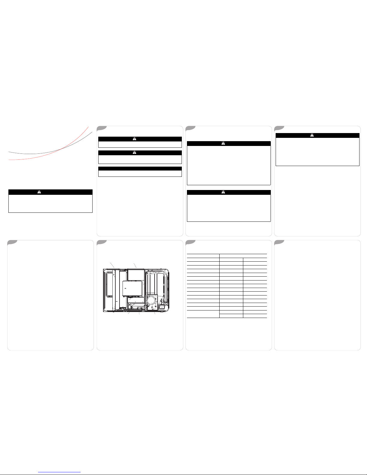
Figure 1. Gas unit overview
RETURN AIR
SUPPLY AIR
PRESSURE SWITCH
GAS VALVE
COMPRESSOR
installed.
Table1. Recommended standard filters
Unit Model Number Filter Size
Inches Millimeters
YH/SC036E*, YHC037E* (2) 20x30x2 (2) 508x762x50
YSC048E* (2) 20x30x2 (2) 508x762x50
YSC060E* (2) 20x30x2 (2) 508x762x50
YHC047E*, YHC048* (4) 16x25x2 (4) 406x635x50
YHC060*, YHC067E* (4) 16x25x2 (4) 406x635x50
YSC072F* (4) 16x25x2 (4) 406x635x50
YSC090F* (4) 16x25x2 (4) 406x635x50
YHC072F* (4) 20x25x2 (4) 508x635x50
YSC092F* (4) 20x25x2 (4) 508x635x50
YSC102F* (4) 20x25x2 (4) 508x635x50
YSC120F* (4) 20x25x2 (4) 508x635x50
YHC092F* (4) 20x25x2 (4) 508x635x50
YHC102F* (4) 20x25x2 (4) 508x635x50
YHC120E* (2) 20x30x2 (2) 508x762x50
(3) 20x25x2 (3) 508x635x50
Heating System
Heating Cycle Operation
Yourunit's heating system hasa solid-state electronic ignitioncontrol that
lights thefurnace burnerseach timethe thermostatcalls forheat. Atthe end
of each heatingcycle the furnace burners are extinguished.This type of
system is called Direct SparkIgnition (DSI).
A normal heating cyclebegins when the air temperature drops below the
thermostat setting.The thermostat then energizes theheating electrical
circuit thatstarts andcontrols thefurnace burners.Shortly afterthe burners
ignite theindoor fanstarts and circulateswarm airthrough the conditioned
space.
When theair temperature risesto the thermostatsetting thethermostat de-
energizes the heating electricalcircuit, which in turn extinguishes the
burners.The indoor fan continues to circulate warm airuntil most of the
heat is removed fromthe unit's combustion chamber.
Safety Controls
• Your unit is equipped with anautomatic reset safety limit control to
prevent overheating.When this control opens, it shuts down the
heating electrical circuit until theunit cools down sufficiently.
Inadequate airflow (i.e., caused bydirty filters or defective fan motor)
maycause theunit tocycle onand offas thelimit tripsand automatically
resets. If you suspect thatthe unit is cycling on its limit control,
immediately contact a service personfor instructions.
• If flames from the burner are not properly drawninto the heat
exchanger, aFlame Rollout Protection Control will open causing the
furnace to shut off.The cause mustbe investigated by a qualified
service person.
• If installed, the condensate overflow switch willshut down the unit
before a drain pan overflowoccurs.
Page 2

8 9 10 11
The manufacturer optimizesthe performance of homes andbuildings around the world. Abusiness of
Ingersoll Rand,the leader in creatingand sustainingsafe, comfortableand energyefficient environments,
the manufacturer offers a broad portfolio of advanced controls and HVAC systems, comprehensive
building services,and parts. Formore information, visitwww.IRCO.com.
The manufacturer hasa policyof continuous productand product dataimprovement andreserves the rightto change
design andspecifications withoutnotice.
© 2013Trane All rightsreserved
RT-SVU03H-EN 13 May2013
Supersedes RT-SVU03G-EN(18 July2012)
Weare committed tousing
environmentally consciousprint
practices thatreduce waste.
Heating System Start-Up
Because your unit has anautomatic ignition system, it is easy to startthe
heating cycle at the beginningof the heating season. In order for the unit
to operate properly andsafely, the furnace needs air forboth combustion
and ventilation. Check to makesure that all air openings areunobstructed
and there is adequate clearancearound the unit to provide good air flow.
1. Set the thermostat's heating adjustmentlever at its lowest setting.
2. Move the selector switchto the Off position.
3. Turn offall electric power to the unit.
4. This unit isequipped with an ignition devicewhich automatically lights
the burners.
5. Remove the access panel thatcontains the following label:
6. Change the ON/OFF switchto the OFF position.
WARNING
HazardousVoltage w/ Capacitors!
Disconnectall electricpower, includingremote disconnectsand discharge
all motor start/run capacitors beforeservicing. Follow proper
lockout/tagout procedures toensure the power cannot be inadvertently
energized.Verify with an appropriate voltmeter that allcapacitors have
discharged. Failureto disconnect power anddischarge capacitors before
servicing could result in deathor serious injury.
WARNING
Risk of Burn!
NEVER attempt to manuallylight the burner! Failure to follow this
recommendation could result in seriousinjury.
Figure 2. Label
REMOVE THIS PANEL
TO GAIN ACCESS TO
THE GAS VALVE
Note: Somevalves requirethe knobto be pushedin slightlybefore turning.
7. Wait (5) minutesto clear outany gas. If youthen smell gas,STOP! Refer
to thewarnings providedin the “GeneralInformation” section.If you do
not smell gas, goto the next step.
8. Change the ON/OFF switchto the ON position.
9. Replace panel removed in step5 above.
10.Turnon all electric power to unit.
11.Set thermostat to desired temperatureand move the selector switchto
the ON position.The unit will now operate automatically.
12.If the unit willnot operate, follow the instructions "ToTurnOff Gas To
Unit" (underHeating SystemShutdown) andcall your servicetechnician
or gas supplier.
Important: The unit is to be adjustedto obtain an air rise within that
specified on the nameplate.
Heating System Shutdown
Toshut down theheating system forbrief periodsof time simplyadjust the
thermostat selector switchto the "Off" position.
NOTICE
Property Damage!
If theunit is shut downduring the cold weathermonths, provisions must
be taken to prevent freeze-upof all water pipes and water receptacles.
Whenever your house or buildingis to be vacant, arrange to have
someone inspect your structure forproper temperature. This isvery
importantin below freezingweather.If for any reason yourfurnace should
fail to operate, damage such as frozen waterpipes could result.
HowToTurn Off GasTo Unit
1. Set the thermostat to lowestsetting.
2. Turn offall electric power to the unit if service isto be performed.
3. Remove the access panel thatcontains the label shown in Figure 2.
4. Change ON/OFF switch tothe "OFF" position.
5. Replace panel removed in step3 above.
WARNING
HazardousVoltage w/ Capacitors!
Disconnectall electricpower, includingremote disconnectsand discharge
all motor start/run capacitors beforeservicing. Follow proper
lockout/tagout procedures toensure the power cannot be inadvertently
energized.Verify with an appropriate voltmeter that allcapacitors have
discharged. Failureto disconnect power anddischarge capacitors before
servicing could result in deathor serious injury.
Heating System Maintenance
Complete the following unit inspectionsand service routines at the
beginning of eachheating season.
Refer to the warningsin “General Information” regarding combustible
materials and what to doif you smell gas.
Important: These steps should only be performedby a qualified service
technician.
1. Inspect the control panel wiring andheating controls to make sure
connections are tight and wiringinsulation is intact.
2. Turnthe unit on and offat the thermostatto be sure the ignitioncontrol
and spark electrode are operatingproperly.
3. Turn offthe gas supply with the unit operating toverify that the gas
valves closes and that are-ignition cycle is initiated by the ignition
control.
4. Check the operation ofthe gas ignition system.
5. Check the burnermanifold pressure. A 1/8inch pipe plug is providedin
the gas valve forthis purpose.
6. Visually inspect allof the unit'sflue product passageways for excessive
deposit build up and corrosion.If build up or corrosion is apparent,
perform the necessary repairs.
7. Arrange fora qualifiedserviceman toinspect theunit everyother heating
season to maintain safe andefficient operation.
8. Visually checkthe mainburner flames.Theyshould bebright blueflames
extending into the heat exchanger sections.
9. Never storeanything flammable orcombustible around ornear the unit.
Condensate Overflow Sensor (Optional)
If installed,the Condensate overflow switchwill shut down theunit before
a drain pan overflowoccur s.
 Loading...