

Page 1
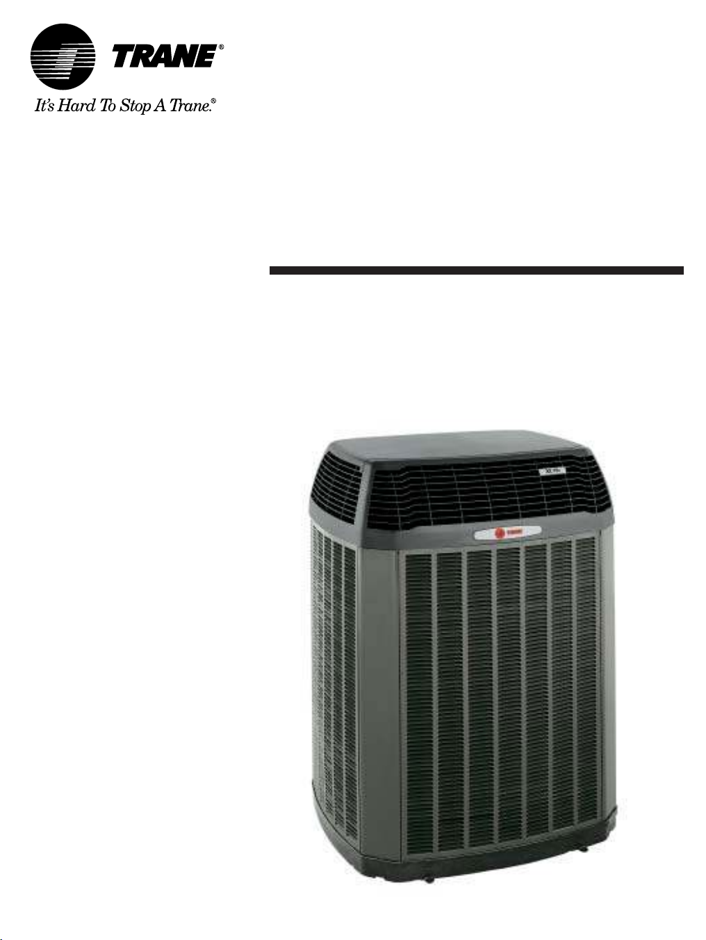
Application Guide
XL19i-APG02-EN
Low Outdoor Operating Temperature
Unit Mounting
Minimum Clearances
Refrigerant Piping Limitations
Trane XL19i heat pumps and cooling units
Page 2

The purpose of this bulletin is to provide cumulative application criteria as related to the Trane XL19i
cooling units and heat pumps.
This bulletin discusses:
I. Off Season Cooling Operation
II. Unit Mounting
III. Minimum Operating Clearances
IV. Refrigerant Piping Limitations
ISSUED BY:
Product Training and Application Department
Trane
Tyler, Texas
Pg. 2
Page 3
Section I - Off Season Cooling Operation
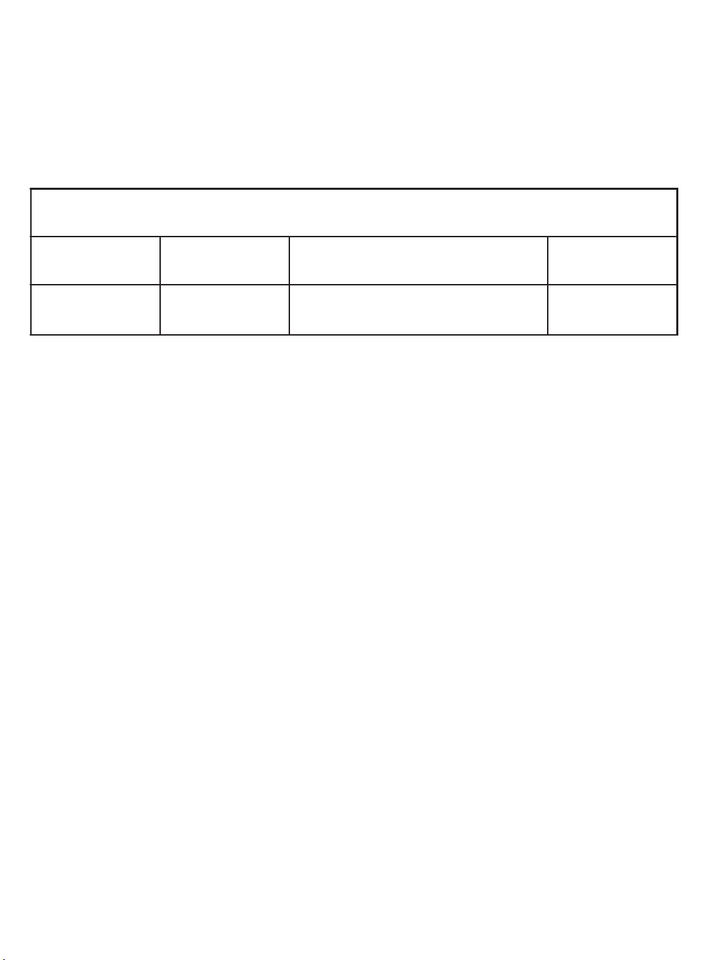
The Trane XL19i may be operated in the cooling mode to 45oF as shipped from the factory. These units
shall only be matched with variable speed air handling units and variable speed furnace / coil combinations.
The coils have factory supplied non - bleed TXV’s
Please refer to the accessory table below when determining if the XL19i will operate at the specified
conditions as well as required accessories.
ERUTAREPMETDO@SEIROSSECCADERIUQER
ledoM54
0
F04/03
0
F0
i91LX deppihSsACDE
Evaporator Defrost Control Kits (EDC)
AY28X079 - Cooling only
AY28X084 - Heat pumps
Compressor Crankcase Heater Kit - BAYCCHT
The Trane XL19i is factory supplied with compressor crankcase heat
Compressor Hard Start Kits - BAYKSKT
XL19i’s are factory supplied with compressor start components.
0
F
toN
devorppA
Pg. 3
Page 4
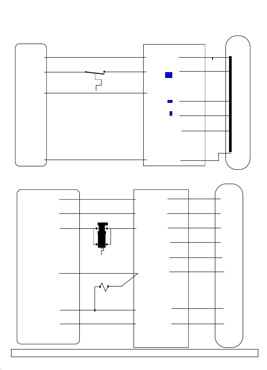
Typical wiring when using the evaporator defrost control (EDC) for operation as specified on page 3.
Cooling Split System and AY28X079 Evaporator Defrost Control
2TTZ9
Red
TWE-E
R
EDC
Y 1
Y
Red (R)
Y low
Y
Green (G)
White (W1)
White (W2)
White (W3)
B
Blue (B)
Heat Pump Split System and AY28X084 Evaporator Defrost Control
2TWZ9
TWE-E
Red (R)
Thermostat
R
Y1
Y2
G
W
W2
B
Thermostat
XT500C
R
Yellow / Red
Yellow
X2
EDR-1
EDC
EDR
Y
Y Low
Green (G)
White (W1)
White (W2)
Y 2
Y 1
G
W1
X2
White (W3)
Blue
Orange
This diagram indicates the correct wiring for the evaporator defrost control. Refer to the installation manual for complete control wiring.
Blue (B)
Orange (O)
Pg. 4
B
O
Page 5
SECTION II - Unit Mounting:
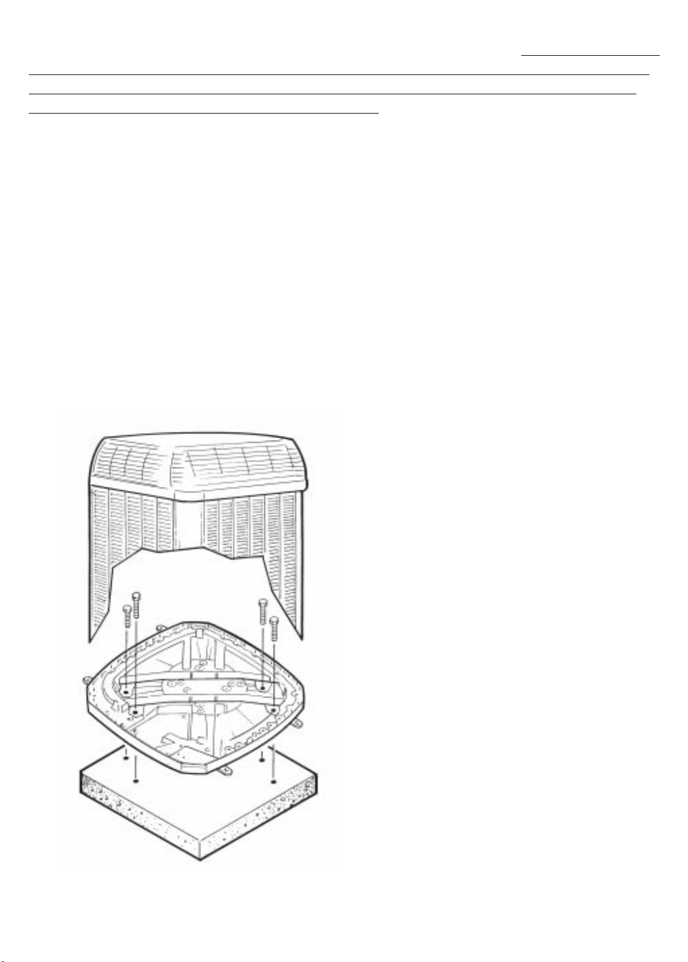
This section describes appropriate methods for mounting and securing the XL19i. However, if these units
are to be mounted in a region where high winds are an issue, please refer to the Trane BAYECMT001
extreme conditions mounting kit. If seizmic restraint is required, please refer local code authority. This
application may require a local P.E.’s approval and stamp.
When mounting or securing the Trane condensing units and heat pumps please observe the following.
1. Anytime the unit is to be supported from the edge, the supporting material shall extend minimum two
inches under the perimeter of the unit’s base.
2. The mounting hole locations are molded in the basepan, however, they must be drilled through.
a) Hole locations are identified on page 6.
b) Hole diameter is 5/16”
3. Washers should be placed in between the fastener head and the basepan.
4. Trane recommends supporting the center of the unit.
5. Base 3 and 4 pans have four mounting holes.
Refer to the dimension tables for actual unit size.
Please refer to the following illustrations for dimensions and general information.
Drawing for illustration purposes only.
Pg. 5
Page 6
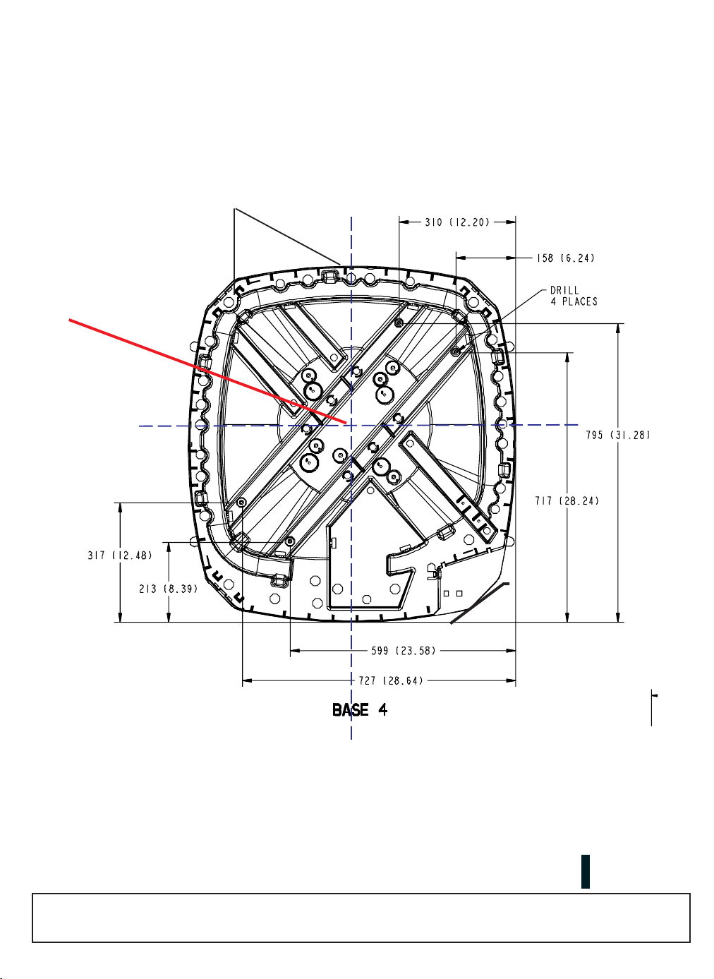
BASE PAN MOUNTING HOLE LOCATIONS
( location only, holes must be drilled )
support must extend 2” from the basepan perimeter
support center of unit
If supporting the base pan from the perimeter, the support must extend under the base pan at least 2”. Trane recommends supporting the middle of the base pan with a cross member.
Pg. 6
Page 7

Section III - Minimum Operating Clearances
This section discusses applying a condensing unit / heat pump in installations where there are space
constraints.
These concerns must be addressed:
1. System Operation - Adequate airflow must be provided to the condensing unit / heat pump in order
to enable appropriate heat transfer. If this is accomplished, head pressure will remain at an effective
operating range.
2. System Servicability - Proper space must be allowed for HVAC service technician to properly
maintain the condensing unit / heat pump. Furthermore, space must be allowed for major component
change out in the event of a failure. Working space is determined by the National Electric Code
3. Space Maintenance - Appropriate area must be allowed in order maintain the ground area where the
units are positioned to prohibit debris from collecting on the panels, thus further providing unobstructed
airflow to the condensing unit.
4. State, Local Codes, and National Codes shall prevail. Check with the local jurisdiction before
installation to assure compliance.
Numerous projects require reduced clearances between outdoor units and adjacent walls, fences and other
units. The obstruction in question is usually one of the following:
1. Deck.
2. One or more walls of an adjacent building.
3. Fences or barriers provided to reduce sound transmission or visually screen the equipment.
4. Other outdoor units in a multi-unit installation.
5. A combination of the above.
The prime considerations involved in establishing minimum clearances are:
1. Adequate airflow to the outdoor coil with minimum recirculation.
2. Service access to the equipment.
3. Compliance with the National Electric Code and other applicable codes.
4. Design temperature - Design temperatures greater than 105F require additional consideration.
I. In order to assure that adequate airflow reaches the XL19i condensing unit, size free air passages at 300
feet per minute velocity (FPM). See condensing unit airflow performance on page 16 of this document; or,
for the most current information, consult the unit’s product data manual.
II. The importance of providing proper service access to equipment cannot be overemphasized. The HVAC
service technician’s job may be performed with greater ease if adequate service space is allowed.
III. Knowledge of the National Electric Code and other applicable codes for the job sight location is a
necessity in order to satisfy local inspectors. These codes are in place for service as well as safety.
IV. Be sure to read all provisions and footnotes contained in this document. When ambient temperatures
exceed 105F, more space may be required for minimum operating clearances.
Pg. 7
Page 8
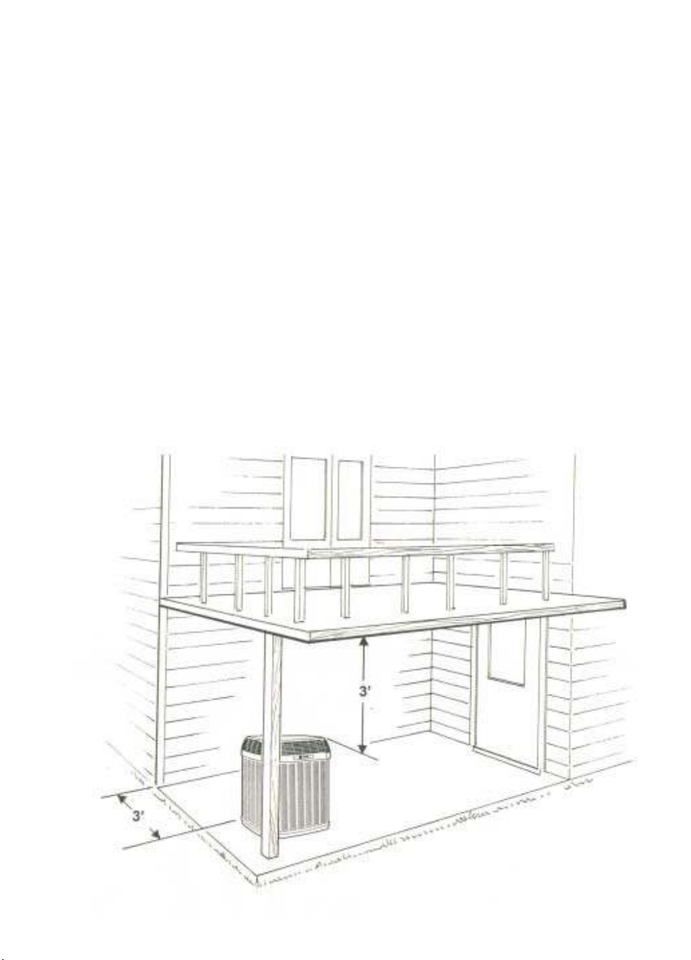
A. Installation of single XL19i unit under a deck.
1. Single XL19i units may be installed under a deck provinding the following criteria is met:
a) 3 feet minimum top clearance is provided.
b) 3 feet away from obstructions such as a wall, or shrubbery on two sides.
c) The other two sides left unobstructed.
d) Decking material overhanging the unit not to exceed two feet on two sides.
e) Servicability - Adequate space provided for annual service and maintenance. National Electric
Code (NEC) requires minimum 3 feet service clearance for personnel safety. This distance may be
increased under certain conditions. Please refer to the most current edition of the National Electric
Code for more information. Page 15 of this document contains some NEC information.
f) Condensing unit shall be set on firm foundation independent from building strucutre, not directly
on ground surface. (Photo below for illustration purposes only)
g) Consult with local building department to assure the installation will comply with local code
before installing the equipment.
Illustrations provided to designate required clearances. Trane recommendeds mounting the unit on a pad
that is independent of the structure. Reference section III.A.1.F on pg 8 of this document.
Pg. 8
Page 9
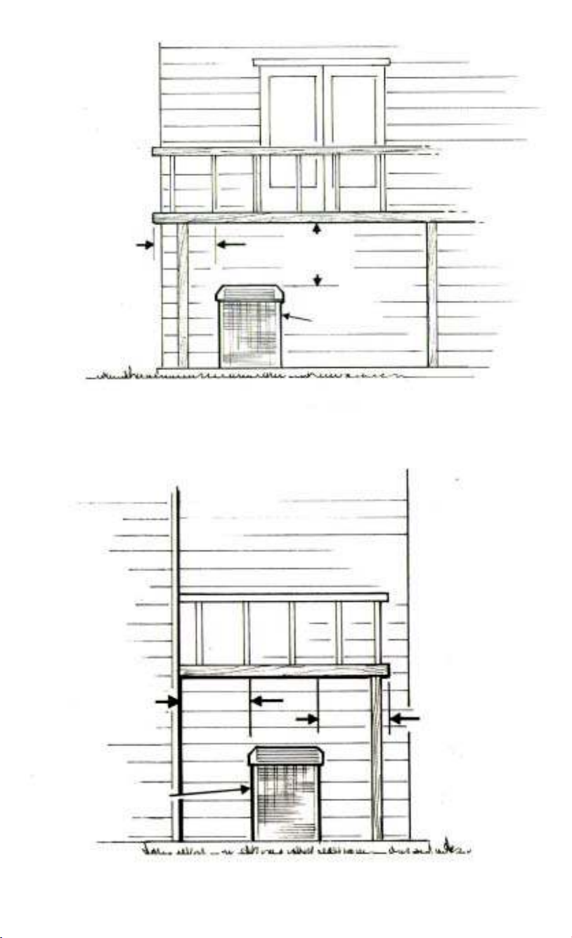
2’ feet maximum
overhang from
side of unit to deck.
3’ minimum
from top of
unit to deck
Outdoor Unit
3’ Minimum clearance from 2 sides of unit to walls
Front View
3’ minimum from
side of unit to
wall of home
Outdoor Unit
Illustrations provided to designate required clearances
2’ maximum
deck overhang
to side of unit
SIDE VIEW
Pg. 9
Page 10
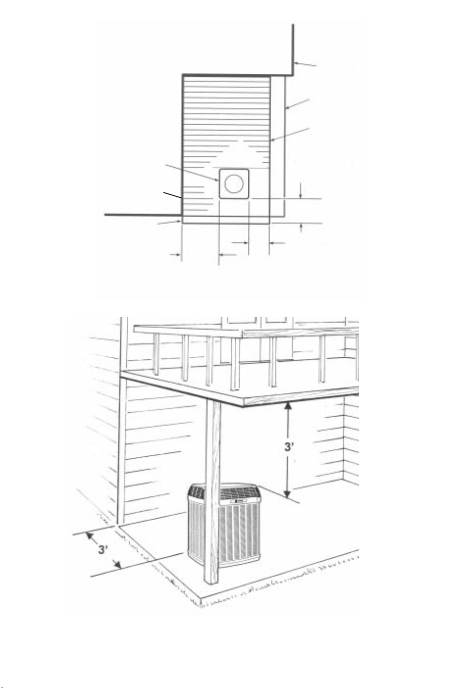
Wall of home
Patio Edge
Deck Edge
Outdoor Unit
Outdoor wall
of home
Deck Edge
3’ Minimum Clearance
from side of unit to
wall of structure
2’ Maximum overhang
from side of unit to
edge of deck
2’ Maximum overhang
from side of unit to
edge of deck
TOP VIEW
ISOMETRIC VIEW
Illustrations provided to designate required clearances. Trane recommendeds mounting the unit on a pad
that is independent of the structure. Reference section III.A.1.F on Pg 8 of this document.
Pg. 10
Page 11
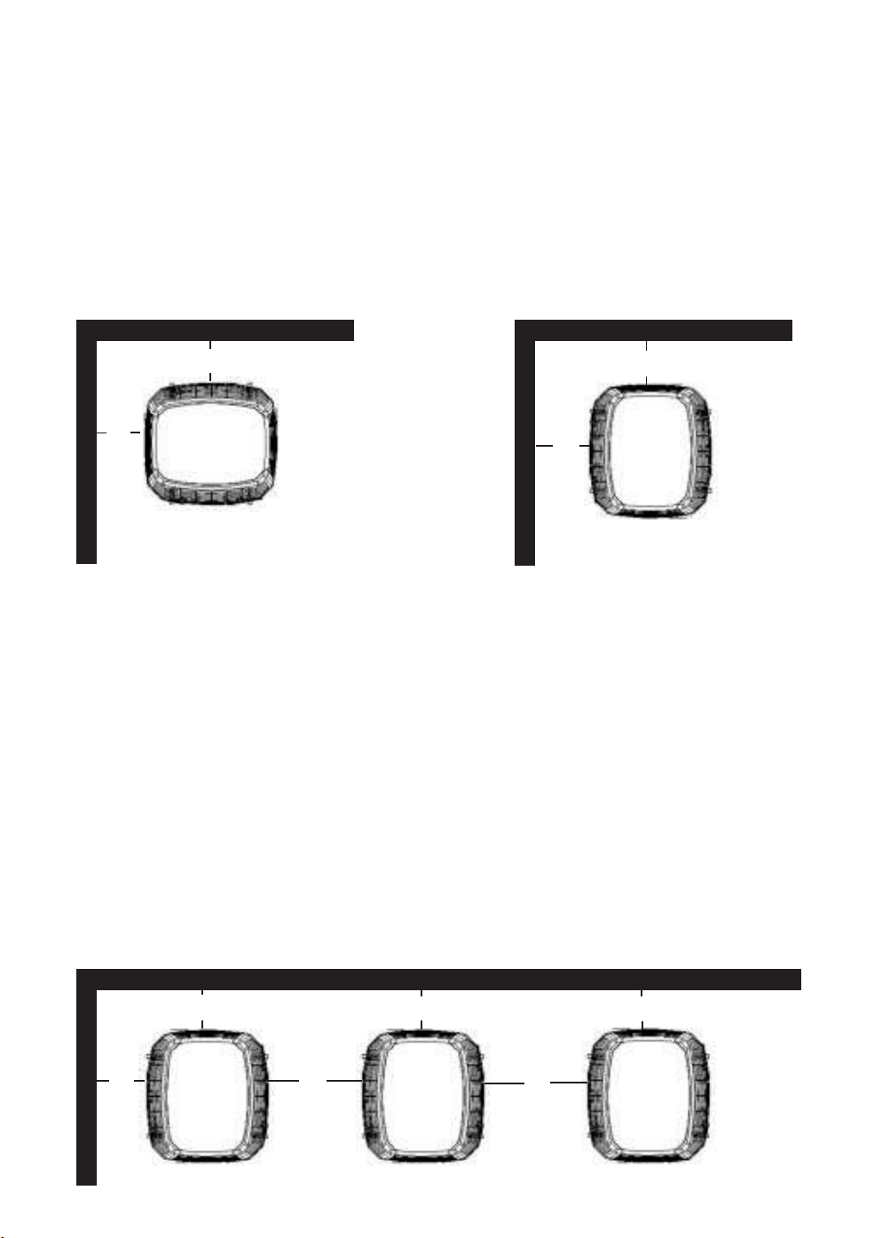
2. Single XL19i condensing unit / heat pump in a corner with unrestricted top clearance
A) For locations where the design ambient temperature is below 105F:
1) 1.5 feet clearance from both walls.
2) Other two sides left unrestricted
B) For locations where the design ambient temperature exceeds 105F:
1) 2.0 feet clearance from both walls.
2) Other two sides left unrestricted.
C) If unit is located in such a way that service panel is facing the wall
1) NEC requires minimum 3 feet between the unit and the wall
a) This space may be increased to 3 1/2 feet. Consult the National Electric Code for more
information regarding minimum clearances for working spaces.
-1.5’min
min
-1.5’-
Service Panel
-1.5’min
Service Panel
min
-1.5’-
3. Installation of two or more XL19i units where two adjacent walls form a corner.
A) For locations where the design ambient temperature is below 105F:
1) Corner unit shall have1.5 feet clearance from both walls.
2) 3.0 feet clearance in between units. ( if service panels face each other, this clearance may be
increased to 4.0 feet per NEC)
3) 2.0 feet clearance from other side to any obstruction
B) For locations where the design ambient temperature exceeds 105F:
1) 2.0 feet clearance from both walls.
2) 3.0 feet clearance in between units. ( if service panels face each other, this clearance may be
increased to 4 feet per NEC)
3) 2.0 feet clearance from other side to any obstruction.
C) If unit’s are located in such a way that the service panels are facing the wall
1) NEC requires minimum 3.0 feet between the unit and the wall
a) This space may be increased to 3 1/2 feet. Consult the most current edition of the National
Electric Code for more information regarding minimum clearances for working spaces.
-1.5’min
min
-1.5’-
min
-1.5’-
-3.0’min
SERVICE ACCESS PANEL SIDE
Pg. 11
-3.0’min
min
-1.5’-
Page 12
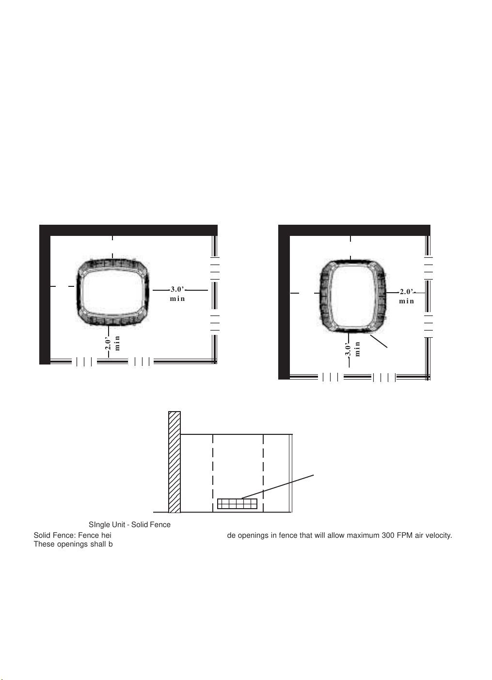
4. Single XL19i condensing unit / heat pump in a fenced corner with unrestricted top clearance
3
3
3
3
3
4
4
4
4
4
4
4
4
4
4
4
4
4
4
4
4
4
4
4
4
7
A) For locations where the design ambient temperature is below 105F:
1) 1.5 feet clearance from both walls.
2) 2.0 feet fence clearance - openings shall be provided to allow free air passage to unit. ( Free air
passage shall be sized @ 300 FPM Velocity)
3) Service access shall be 3.0 feet minimum
B) For locations where the design ambient temperature exceeds 105F:
1) 2.0 feet clearance from both walls.
3) 3.0 feet clearance from fence. openings shall be provided to allow free air passage to unit. ( Free
air passage shall be sized @ 300 FPM Velocity)
2) Service access shall be 3.0 feet minimum.
C) If unit is located in such a way that service panel is facing the wall
1) NEC requires minimum 3 feet between the unit and the wall
a) This space may be increased to 3 1/2 feet. Consult the National Electric Code for more
information regarding minimum clearances for working spaces.
-1.5’min
-1.5’-
min
-2.0’-
min
Service Panel
-3.0’min
2
2
-1.5’min
2
2
2
min
-1.5’-
min
-3.0’-
-2.0’min
Service Panel
* If removable panels are used and acceptable to local inspection agency, the clearance to the removable
panel may be reduced to 2.0 feet
23
23
23
23
23
23
23
23
23
23
23
23
23
23
23
23
23
23
23
23
opening size @
300 FPM maximum
velocity
23456
SIngle Unit - Solid Fence
Solid Fence: Fence height not to exceed top of unit. Provide openings in fence that will allow maximum 300 FPM air velocity.
These openings shall be located at the lower portion of the fence. If acceptable, the lower portion of the fence may be cut to
provide open bottom clearance provided that debris, grass and vegetation will not obstruct air passageway.
Pg 12
Page 13
4
4
4
4
4
4
4
4
4
4
4
4
4
4
4
4
4
4
4
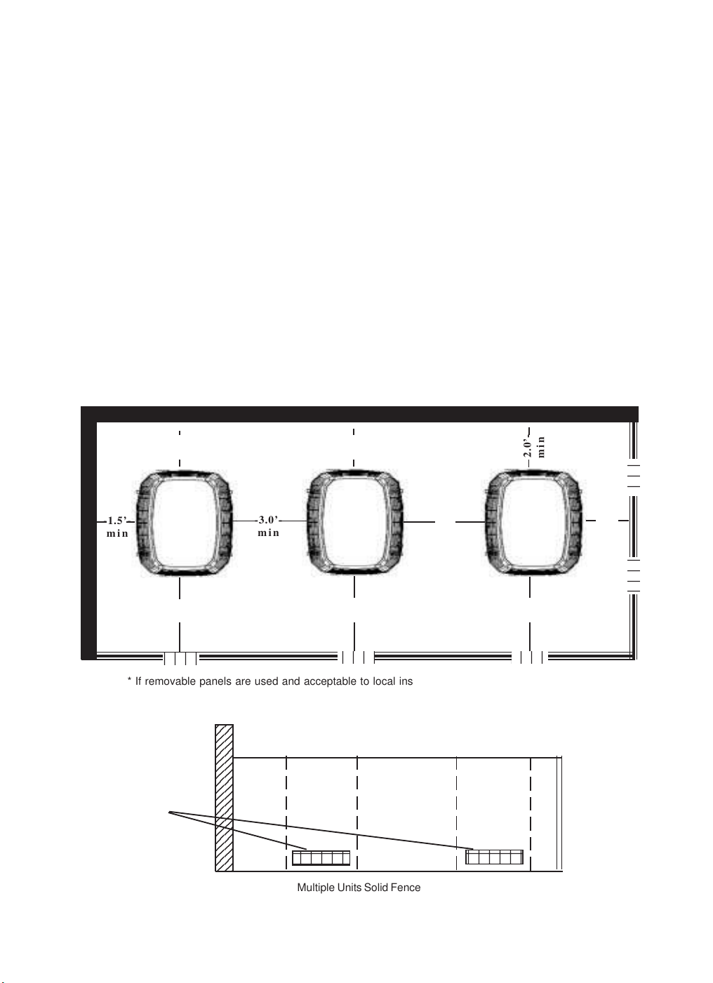
5. Installation of two or more XL19i units where two adjacent walls form a fenced corner
A) For locations where the design ambient temperature is below 105F:
1) Corner unit shall have1.5 feet clearance from one wall and 2.0 feet clearance from the other wall.
2) 3.0 feet clearance in between units.
3) NEC requires 3 feet clearance for service. This may be reduced to 2.0 feet if removable panels
are used.
4) Free air passage shall be cut in order to allow maximum 200 FPM air velocity
B) For locations where the design ambient temperature exceeds 105F:
1) Corner unit shall have 2.0 feet clearance from one wall and 2.5 feet clearance from the other
wall.
2) 3.5 feet clearance in between units.
3) NEC requires 3 feet clearance for service. This may be reduced to 2.5 feet if removable panels
are used.
C) If unit’s are located in such a way that the service panels are facing the wall
1) NEC requires minimum 3.0 feet between the unit and the wall
a) This space may be increased to 3 1/2 feet. Consult the most current edition of the National
Electric Code for more information regarding minimum clearances for working spaces.
-1.5’min
min
-2.0’-
min
-3.0’-
-3.0’min
min
-2.0’-
min
-3.0’-
-3.0’min
min
-2.0’-
min
-3.0’-
-1.5’min
SERVICE ACCESS PANEL SIDE*
* If removable panels are used and acceptable to local inspection agency, the clearance to the
removable panel may be reduced to 2.0 feet
23
23
23
23
23
23
23
23
opening size @
300 FPM maximum
velocity
Solid Fence: Fence height not to exceed top of unit. Provide openings in fence that will allow maximum 300 FPM air velocity. These
openings shall be located at the lower portion of the fence. If acceptable, the lower portion of the fence may be cut to provide open
bottom clearance provided that debris, grass and vegetation will not obstruct air passageway.
23
23
23
23
23
23
23
23
23
23
23
Multiple Units Solid Fence
Pg 13
Page 14
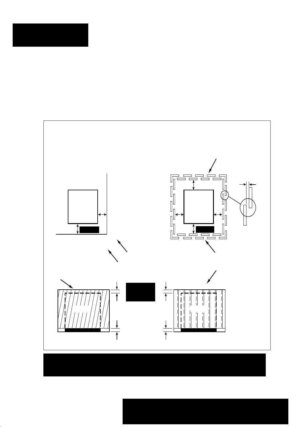
D) Fence construction.
1) Height shall not exceed the top of the unit.
2) Free air passages shall be size at no greater than 300 FPM velocity.
3) Free air passages shall be cut at the lower portion of the fence.
4) Fence may also be undercut to allow free air passage provided grass, vegetation, or debris will
not obstruct the free air passage.
5) Shrubbery shall not be planted within one foot of the fence.
6) If removable panel is utilized, the distance from the unit’s service panel to the removable panel
may be reduced to 2.0 feet. (3.0 feet if geographical location’s design outdoor dry bulb is greater
than 1050 F.
E) Windshields:
If low ambient operation to 30F is required, windshields may be required to block prevailing winds
from impacting system performance at low outdoor temperatures.
SHIELD DESIGN FOR
HIGHLY DIRECTIONAL WINDS
SERVICE
ACCESS
AREA
SEE NOTES
UNIT
12" MIN.
1.5’
1.5’ 1.5’
PREVAILING
WIND DIRECTION
SOLID PANEL
Shadow Box Fence shall
24" MAXIMUM
not exceed unit’s top
UNIT
4" MINIMUM
height
SHIELD DESIGNED FOR
NON-DIRECTIONAL WINDS
SERVICE
ACCESS
AREA
SEE NOTES
UNIT
1.5’
12" MIN.
REMOVEABLE PANEL
OR GATE
FOR SERVICE
2 1/2" MIN.
SHADOW BOX FENCE
33% MIN. FREE AREA
EACH SIDE
UNIT
2" MINIMUM
4" MAXIMUM
Notes:
Note:
• Service access working clearance (3 feet) for electrical and refrigerant components must meet NEC Article 110-16
requirements and local codes.
Minimum working clearance must be in compliance with the National Electric Code. Currently,
the minimum clearance between a wood or suitable grounding material type fence requires
minimum 3 feet. If other material is used to form the windshield, the minimum space may be
increased to 3.5 feet. Please consult the 2002 or current Edition of the National Electric Code,
Article 110 for the most up to date information
Pg 14
66
22-3237-02
Page 15
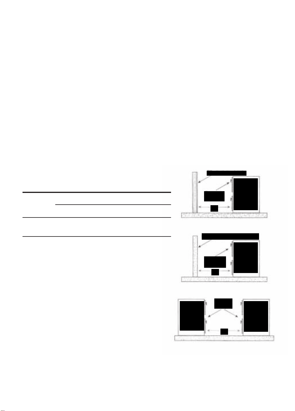
Electrical Code Information
Compliance with Local, State, and National Codes is a must on every HVAC Installation. This page
discusses the criteria regarding minimum working spaces as defined in the 2002 National Electric Code.
The main concern is the safety of the HVAC service / maintenance person. Minimum working clearances
are specified in the National Electric Code (NEC) Article 110.26
For electrical equipment that from ground to power the voltage is 600 volts or less:
The National Electric Code specifically states that service area around electrical equipment shall provide
sufficient access, and shall be properly maintained in order to permit safe operation and maintenance of the
equipment. Table 110.26 as well as the figures beside the table describe the minimum clearance for proper
service and access to electrical equipment.
Trane residential and light commercial condensing units ranging from 1 to 6 ton require access to the side
service panel as indicated on the previous pages to gain access to the electrical controls.
The table and figure below are excerpts from the National Electric Code 2002:
Table 110.26(A)(1) Working Clearances
Nominal
Voltage to
Ground
0-150 900 mm (3 FT) 900 mm (3 FT) 900 mm (3FT)
151-600 900 mm (3FT) 1 M (3.5FT) 1.2 mm (4FT)
Note: Where the conditions are as follows
Condition 1 - Exposed live parts on one side and no live or grounded parts
on the other side of the working space, or exposed live parts on both sides
effectively guarded by suitable wood or other insulating materials. Insulated
wire or insulated busbars operating at not over 300 volts to ground shall not
be considered live parts
Condition 2 - Exposed live parts on one side and grounded parts on the
other side. Concrete, brick, or tile walls shall be considered as grounded.
Condition 3 - Exposed live parts on both sides of the work space (not
guarded as provided in Condition 1) with the operator between.
Condition 1 Condition 2 Condition 3
Minimum Clear Distance
(Space would increase to 3 1/2 ft for 151 - 600 V)
(3 ft min. for 151 - 600 V)
Exposed
Live Parts
Electric
switchboard
150V nominal
or less
Effectively Insulated
Electric
switchboard
Exposed
Live Parts
3’
Condition 1
Grounded parts, concrete, etc
3’
Condition 2
Exposed
Live Parts
150V nominal
or less
Electric
switchboard
150V nominal
or less
Electric
switchboard
150V nominal
or less
3’
(Space would increase to 4 ft for 151 - 600 V)
Condition 3
Reprinted with permission from NFPA 70-2002, National Electrical Code®, Copyright © 2001, National Fire
Protection Association. This reprinted material is not the complete and official position of the NFPA on the
referenced subject, which is represented only by the standard of it’s entirety.
National Electrical Code and NEC are registered trademarks of the National Fire Protection Association, Quincy, MA.
Pg. 15
Page 16
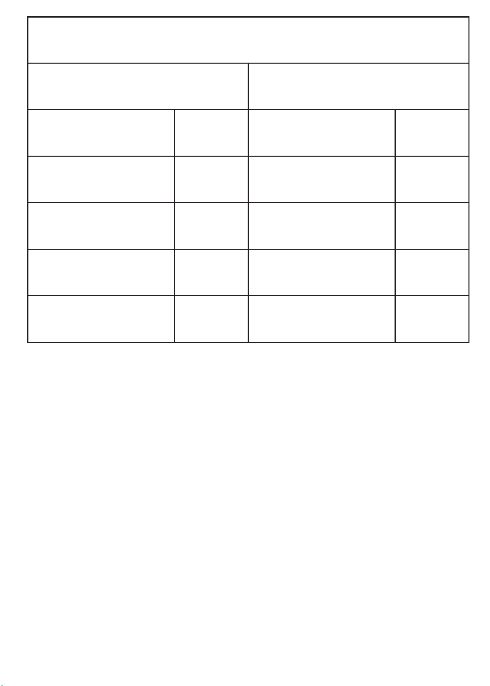
elbaTwolfriAtinUroodtuOi91LX
stinUgnilooCstinUpmuPtaeH
rebmuNledoMtinUMFCrebmuNledoMtinUMFC
A0001A0309ZTT25704A0001A0309ZWT25704
A0001A6309ZTT25704A0001A6309ZWT25704
A0001A8409ZTT25704A0001A8409ZWT25704
A0001A0609ZTT25704A0001A0609ZWT25704
*Table produced Jan. 2003. For the most current information, please refer to specific equipment Product Data.
Required Opening = CFM / 300 FPM
Example:
Given:
Qty of 2 units in an area surrounded by a fence on two sides and solid walls on the other two sides. Units
are 2TTZ9030A100A’s -
Required:
Determine free air opening space required in fence -
Solution:
4075CFM X Qty of 2 = 8150 CFM
8150 CFM / 300 FPM = 27.17 square feet
Round 27.17 to 27 square feet of free air opening in the 2 fence sections surrounding the units.
Pg. 16
Page 17

XL19i Unit Dimensions
ledoMtinUesaBABC ledoMtinUeziSesaBABC
A0001A0309ZTT24"8/794"4/173"4/143A0001A0309ZWT24"8/794"4/173"4/143
A0001A6309ZTT24"8/794"4/173"4/143A0001A6309ZWT24"8/794"4/173"4/143
A0001A8409ZTT24"8/794"4/173"4/143A0001A8409ZWT24"8/794"4/173"4/143
A0001A0609ZTT24"8/794"4/173"4/143A0001A0609ZWT24"8/794"4/173"4/143
Pg. 17
Page 18
Section IV - Refrigerant Piping
A. Purpose
1. Liquid line - The purpose of the liquid refrigerant line is to convey refrigerant, in the liquid state, from
the outdoor unit to the indoor unit in the cooling mode and from the indoor unit to the outdoor unit in the
heating mode.
2. Gas line - The purpose of the gas line is to convey refrigerant in the gas state and oil from the indoor unit
to the outdoor unit in the cooling mode and from the outdoor unit to the indoor unit in the heating mode.
B. Limitations:
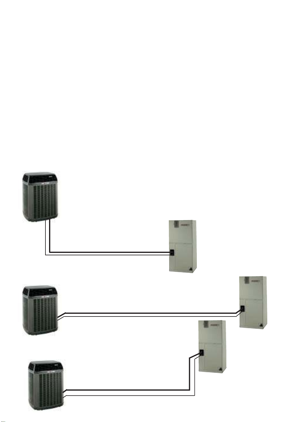
1. The XL19i contains two compressors that share the same refrigeration circuit, however, do not operate
simultaneously. Therefore, it is crucial that refrigerant lines are properly sized and do not exceed the length
set forth in the unit’s installation manual.
2. Line length limits:
A. Gas line = 80 feet linear length / of the linear length, 25 feet may be installed vertical.
B. Liquid line = 80 feet linear length / of the linear length, 25 feet may be installed vertical.
3. No exceptions shall be allowed to these piping limitations.
C. Explanation:
1. Refrigerant lines shall not exceed 80 feet total line length. / 25 feet of the 80 feet may be vertical. .
2. Liquid subcooling may not be achieved on first stage if the liquid line exceeds 80 feet.
3. Oil return may be sacrificed during first stage operation if the gas line exceeds 80 feet.
25 Ft. Max
55 Ft. Max
80 Feet Max.
25 Ft. Max
vertical
55 Ft. Max
Pg. 18
Page 19
NOTES
Pg. 19
Page 20
Trane
6200 Troup Highway
Tyler, TX 75707
http://www.trane.com
Literature Order Number
File Number XL19i-APG02-EN 03/04
Supersedes XL19i-APG01-EN 01/03
Stocking Location
Since Trane has a policy of continuous product improvement, it reserves the right to change
design and specifications without notice
 Loading...