


Installation
Operation
Maintenance
RTUB 207-224 - Liquid chillers with helical rotary compressors
RTCA 108-216 - Remote air-cooled condenser
RLC-SVX03A-E4
Foreword
These installation, operation and maintenance instructions are given as a guide to good practice in the installation, putting into service, operation, and maintenance by the user ofTrane RTUB and RTCA units. They do not contain full service procedures necessary for the continued successful operation of this equipment;The services of a qualified technician should be employed through the medium of a maintenance contract with a reputable service company.
Warranty
Warranty is based on the general terms and conditions of Société Trane orTrane UK Ltd.The warranty is void if the equipment is repaired or modified without the written approval ofTrane, if the operating limits are exceeded or if the control system or the electrical wiring is modified.
Damage due to misuse, lack of maintenance or failure to comply with the manufacturer's instructions or recommendations is not covered by the warranty obligation.
If the user does not conform to the rules of chapter "Maintenance", it may entail cancellation of warranty and liabilities byTrane.
Reception of the unit
On arrival, inspect the unit before signing the delivery note. Specify any damage on the delivery note, and send a registered letter of protest to the last carrier of the goods within 72 hours of delivery. Notify the localTrane Sales Office at the same time.The unit should be totally inspected within 7 days of delivery. If any concealed damage is discover, send a registered letter of protest to the carrier within 7 days of delivery and notify the localTrane Office.
Units are shipped with the refrigerant operating or holding charge and should be examined with an electronic leak detector to determine the hermetic integrity of the unit.The refrigerant charge is not included in the standardTrane Warranty Cover.
Cautions and warnings
Cautions and warnings appear at appropriate places in this instruction manual.Your personal safety and the proper operation of this machine require that you follow them carefully.The constructor assumes no liability for installations or servicing performed by unqualified personnel.
Refrigerant
The refrigerant provided by Société Trane orTrane UK Ltd meets all the requirements of our units. When using recycled or reprocessed refrigerant, it is advisable to ensure its quality is equivalent to that of a new refrigerant. For this, it is necessary to have a precise analysis made by a specialized laboratory. If this condition is not respected, the SociétéTrane UK Ltd warranty could be cancelled.
©American Standard Inc. 2002 |
RLC-SVX03A-E4 |
Contents
Foreword |
2 |
|
|
Warranty |
2 |
|
|
Reception of unit |
2 |
|
|
Cautions and warnings |
2 |
|
|
Refrigerant |
2 |
General information
Unit Inspection |
5 |
|
|
Inspection Checklist |
5 |
|
|
Loose Parts Inventory |
6 |
|
|
Description of the Unit |
6 |
|
|
General Data RTUB |
7 |
|
|
General Data RTCA |
8 |
Installation
Installation Responsibilities |
9 |
|
|
Storage |
9 |
|
|
Special Lifting and Moving Instructions |
10 |
|
|
Isolation |
10 |
|
|
Foundation |
10 |
|
|
Clearances |
11 |
|
|
Drainage |
12 |
|
|
Releasing the Nitrogen Holding Charge |
12 |
|
|
Water Connections (RTUB) |
12 |
|
|
Flow Switch Installation |
13 |
|
|
Water Pressure Gauges |
13 |
|
|
Refrigeration Safety Valves |
14 |
|
|
Water Pressure Relief Valves |
14 |
|
|
Installing and ConnectingTemperature Sensors |
14 |
|
|
Connecting RTUB with the Remote Air-cooled Condenser |
15 |
RLC-SVX03A-E4 |
3 |
Contents
Operation
Pre-start Checkout |
21 |
|
|
Unit Voltage Power Supply |
21 |
|
|
Unit Voltage Imbalance |
21 |
|
|
Unit Voltage Phasing |
21 |
|
|
Water System Flow Rates |
22 |
|
|
Water System Pressure Drop |
22 |
|
|
Daily Unit Start-up Procedure |
22 |
|
|
Seasonal Unit Start-up Procedure |
23 |
|
|
Temporary Shutdown and Restart |
23 |
|
|
Extended Shutdown Procedure |
23 |
|
|
System Restart after Extended Shutdown |
23 |
Maintenance
Periodic Maintenance |
25 |
|
|
Refrigerant and Oil Charge Management |
27 |
|
|
R134a Field-charging Procedure |
28 |
|
|
Charge Isolation on the High or Low Side of the System |
28 |
|
|
Filter Replacement Procedure |
29 |
|
|
Lubrication System |
29 |
|
|
Oil Charging Procedure |
29 |
|
|
Safety Recommendations |
32 |
|
|
Maintenance Contract |
32 |
|
|
Training |
32 |
4 |
CG-PRC010-E4 |

General information
This manual describes installation, operation, and maintenance of RTUB and RTCA units.
A separate manual is available for the use and maintenance of the RTUB controls (UCM-CLD).
Unit Inspection
When the unit is delivered, verify that it is the correct unit and that it is property equipped. Compare the information that appears on the unit nameplate with the ordering and submittal information. A typical unit nameplate is shown in Figure 1. Inspect all exterior components for visible damage. Report any apparent damage or material shortage to the carrier and make a "unit damage" notation on the carrier's delivery receipt. Specify the extent and type of damage found and notify the appropriateTrane Sales Office. Do not proceed with installation of a damaged unit without sales office approval.
Inspection Checklist
To protect against loss due to damage incurred in transit, complete the following checklist upon receipt of the unit.
• Inspect the individual pieces of the shipment before accepting the unit. Check for obvious damage to the unit or packing material.
• Inspect the unit for concealed damage as soon as possible after delivery and before it is stored. Concealed damage must be reported within 15 days.
If concealed damage is discovered, stop unpacking the shipment. Do not remove damaged material from the receiving location.Take photos of the damage, if possible.The owner must provide reasonable evidence that the damage did not occur after delivery.
• Notify the carrier's terminal of the damage immediately, by phone and by mail. Request an immediate, joint inspection of the damage with the carrier and the consignee.
RLC-SVX03A-E4 |
5 |

Figure 1 - Typical Unit Nameplates
RTUB


 é
é
General information
•Notify theTrane sales representative and arrange for repair. Do not repair the unit, however, until damage is inspected by the carrier's representative.
Loose Parts Inventory
Check all the accessories and loose parts that are shipped with the unit against the shipping list. Included in these items will be water vessel drain plugs, rigging and electrical diagrams, and service literature, which are placed inside the control panel and/or starter panel for shipment.
been assembled and wired in the factory.The discharge piping is blocked at the oil separator outlet. Water connections - chilled water inlet and outlet - are blocked for transportation. Both RTUB and RTCA units are dried and vacuum-pumped in the factory, and contain a nitrogen holding charge when shipped.
Description of the Unit
The RTUB units are liquid chillers equipped with two helical rotary compressors and an evaporator designed to operate with remote RTCA air-cooled condensers or other manufacturers' remote condensers. The RTUB is shipped once it has
RTCA
6 |
RLC-SVX03A-E4 |
General information
Table 1 - General data - RTUB
Unit size |
|
207 |
208 |
210 |
211 |
212 |
214 |
Compressor |
|
|
|
|
|
|
|
Type/quantity |
|
|
|
Helical rotary/2 |
|
|
|
Nominal size |
(tons) |
35/35 |
40/40 |
50/50 |
60/50 |
60/60 |
70/70 |
Evaporator |
|
|
|
|
|
|
|
Evaporator Model |
|
EG 120 |
EG 120 |
EG 140 |
EG 170 |
EG 170 |
EG 200 |
Water Storage |
(l) |
105 |
105 |
365 |
220 |
220 |
200 |
Minimum Flow |
(l/s) |
4.5 |
4.5 |
6.0 |
7.0 |
7.0 |
9.0 |
Maximum Flow |
(l/s) |
13.4 |
13.4 |
18.0 |
21.0 |
21.0 |
25.0 |
Evaporator inlet diameter |
(inches) |
5 |
5 |
6 |
6 |
6 |
6 |
Evaporator outlet diameter |
(inches) |
5 |
5 |
6 |
6 |
6 |
6 |
Minimum Starting/ |
|
|
|
|
|
|
|
Operating Ambient |
(°C) |
|
|
|
5 |
|
|
Refrigerant |
|
|
|
|
R134a |
|
|
Number of Independent |
|
|
|
|
|
|
|
Refrigerant Circuits |
|
|
|
|
2 |
|
|
Percent Minimum Load |
(%) |
|
|
|
17 |
|
|
Refrigerant Charge |
(kg) |
26 |
26 |
40 |
40 |
40 |
40 |
Oil Charge |
(l) |
12 |
12 |
14 |
14 |
14 |
16 |
Operating Weight |
(kg) |
2130 |
2130 |
2845 |
2845 |
2845 |
3250 |
Shipping Weight |
(kg) |
1860 |
1860 |
2570 |
2570 |
2570 |
2975 |
Unit size |
|
216 |
217 |
218 |
220 |
222 |
224 |
Compressor |
|
|
|
|
|
|
|
Type/Quantity |
|
|
|
Helical rotary/2 |
|
|
|
Nominal size |
(tons) |
70/85 |
85/85 |
100/85 |
100/100 |
120/100 |
120/120 |
Evaporator |
|
|
|
|
|
|
|
Evaporator Model |
|
EG 200 |
EG 200 |
EG 250 |
EG 250 |
EG 340 |
EG 340 |
Water Storage |
(l) |
200 |
200 |
415 |
415 |
560 |
560 |
Minimum Flow |
(l/s) |
9.0 |
9.0 |
11.0 |
11.0 |
14.0 |
14.0 |
Maximum Flow |
(l/s) |
25.0 |
25.0 |
33.0 |
33.0 |
43.0 |
43.0 |
Evaporator inlet diameter |
(inches) |
6 |
6 |
6 |
6 |
6 |
6 |
Evaporator outlet diameter |
(inches) |
6 |
6 |
6 |
6 |
6 |
6 |
Minimum Starting/ |
|
|
|
|
|
|
|
Operating Ambient |
(°C) |
|
|
|
5 |
|
|
Refrigerant |
|
|
|
|
R134a |
|
|
Number of Independent |
|
|
|
|
|
|
|
Refrigerant Circuits |
|
|
|
|
2 |
|
|
Percent Minimum Load |
(%) |
|
|
17 |
|
|
|
Refrigerant Charge |
(kg) |
40 |
40 |
46 |
46 |
50 |
50 |
Oil Charge |
(l) |
16 |
16 |
16 |
16 |
19 |
22 |
Operating Weight |
(kg) |
3250 |
3250 |
3880 |
4050 |
4480 |
4550 |
Shipping Weight |
(kg) |
2975 |
2975 |
3405 |
3575 |
3855 |
3925 |
RLC-SVX03A-E4 |
7 |
General information
Table 2 - General data - RTCA
Unit size |
|
108 |
109 |
111 |
113 |
115 |
116 |
Condenser |
|
|
|
|
|
|
|
Condenser type |
|
|
|
Aluminium fins/copper tubes |
|
|
|
Fin spacing |
(fins/ft) |
168 |
168 |
144 |
168 |
168 |
144 |
Frontal surface area |
(m²) |
5.7 |
6.9 |
6.9 |
11.3 |
11.7 |
13.7 |
Airflow |
|
|
|
|
|
|
|
Standard unit |
(m3/h) |
42500 |
50400 |
69300 |
77200 |
84700 |
98500 |
Low noise unit |
(m3/h) |
34500 |
40900 |
56300 |
62700 |
68800 |
80000 |
Condenser fans |
|
|
|
|
|
|
|
Number of fans |
|
4 |
4 |
6 |
8 |
8 |
12 |
Fan speed |
|
|
|
|
|
|
|
Standard unit |
(rpm) |
|
|
|
690 |
|
|
Low noise unit |
(rpm) |
|
|
|
560 |
|
|
Nominal fan power |
|
|
|
|
|
|
|
Standard unit |
(kW) |
|
|
|
0.85 |
|
|
Low noise unit |
(kW) |
|
|
|
0.54 |
|
|
Current fan amps |
|
|
|
|
|
|
|
Standard unit |
(A) |
|
|
|
2.4 |
|
|
Low noise unit |
(A) |
|
|
|
1.2 |
|
|
Minimum Starting/ |
|
|
|
|
|
|
|
Operating Ambient (1) |
(°C) |
|
|
7 Standard units/-18 Low ambient units |
|
|
|
Refrigerant |
|
|
|
|
R134a |
|
|
Number of Independent |
|
|
|
|
|
|
|
Refrigerant Circuits |
|
1 |
1 |
1 |
1 |
1 |
1 |
Refrigerant Charge |
(kg) |
22 |
26 |
36 |
44 |
52 |
72 |
Operating Weight (2) |
(kg) |
810 |
890 |
1090 |
1535 |
1770 |
2050 |
Shipping Weight (2) |
(kg) |
1020 |
1100 |
1300 |
1870 |
2170 |
2450 |
Hot gas connection |
(inches) |
1 5/8 |
1 5/8 |
1 5/8 |
1 5/8 |
1 5/8 |
1 5/8 |
Liquid connection |
(inches) |
1 1/8 |
1 1/8 |
1 1/8 |
1 1/8 |
1 1/8 |
1 1/8 |
Unit size |
|
208 |
209 |
211 |
213 |
215 |
216 |
Condenser |
|
|
|
|
|
|
|
Condenser type |
|
|
|
Aluminium fins/copper tubes |
|
|
|
Fin spacing |
(fins/ft) |
168 |
168 |
144 |
168 |
168 |
144 |
Frontal surface area |
(m²) |
5.7 |
6.9 |
6.9 |
11.3 |
11.7 |
13.7 |
Airflow |
|
|
|
|
|
|
|
Standard unit |
(m3/h) |
42500 |
50400 |
69300 |
77200 |
84700 |
98500 |
Low noise unit |
(m3/h) |
34500 |
40900 |
56300 |
62700 |
68800 |
80000 |
Condenser fans |
|
|
|
|
|
|
|
Number of fans |
|
2 x 2 |
2 x 2 |
2 x 3 |
2 x 4 |
2 x 4 |
2 x 6 |
Fan speed |
|
|
|
|
|
|
|
Standard unit |
(rpm) |
|
|
|
690 |
|
|
Low noise unit |
(rpm) |
|
|
|
560 |
|
|
Nominal fan power |
|
|
|
|
|
|
|
Standard unit |
(kW) |
|
|
|
0.85 |
|
|
Low noise unit |
(kW) |
|
|
|
0.54 |
|
|
Current fan amps |
|
|
|
|
|
|
|
Standard unit |
|
|
|
|
2.4 |
|
|
Low noise unit |
|
|
|
|
1.2 |
|
|
Minimum Starting/ |
|
|
|
|
|
|
|
Operating Ambient (1) |
(°C) |
|
|
7 Standard units/-18 Low ambient units |
|
|
|
Refrigerant |
|
|
|
|
R134a |
|
|
Number of Independent |
|
|
|
|
|
|
|
Refrigerant Circuits |
|
2 |
2 |
2 |
2 |
2 |
2 |
Refrigerant Charge |
(kg) |
2 x 11 |
2 x 13 |
2 x 18 |
2 x 22 |
2 x 26 |
2 x 36 |
Operating Weight (2) |
(kg) |
810 |
890 |
1090 |
1535 |
1770 |
2050 |
Shipping Weight (2) |
(kg) |
1020 |
1100 |
1300 |
1870 |
2170 |
2450 |
Hot gas connection |
(inches) |
1 5/8 |
1 5/8 |
1 5/8 |
1 5/8 |
1 5/8 |
1 5/8 |
Liquid connection |
(inches) |
1 1/8 |
1 1/8 |
1 1/8 |
1 1/8 |
1 1/8 |
1 1/8 |
(1)Based on a 2.2 m/s wind across the condenser
(2)With aluminium fins
8 |
RLC-SVX03A-E4 |
Installation
Installation responsibilities
Generally, the contractor must do the following when installing an RTUB/RTCA unit.
•Install the units on a flat foundation, level (within 1/4" [6 mm] across the length of the
unit), and strong enough to support unit loading.
•Install the units per the instructions contained in the Installation section of this manual.
•Install any optional sensors and make electrical connections at the UCM-CLD.
•Where specified for the RTUB, provide and install valves in the water piping upstream and downstream of the evaporator water connections, to isolate the evaporator for maintenance and to balance and trim the system.
•Furnish and install a flow switch and/or auxiliary contacts to prove chilled-water flow.
•Furnish and install pressure gauges in the inlet and outlet piping of the evaporator (for RTUB).
•Furnish and install a drain valve to the bottom of the evaporator water box (for RTUB).
•Supply and install a vent cock to the top of the evaporator water box (for RTUB).
•Furnish and install strainers ahead of all pumps and automatic modulating valves.
•Furnish and install check valves on the discharge lines (between oil separators and condenser) in order to avoid any refrigerant migration leading to catastrophic damages to evaporator and/or compressor (due to freeze-up or liquid slugging).
•Interconnect the RTUB and the remote condenser.
•Provide and install field wiring.
•Install heat tape and insulate the chilled-water lines and any other portions of the system, as required, to prevent sweating under normal operating conditions or freezing during low-ambient temperature conditions.
•Start the unit under the supervision of a qualified service technician.
Storage
If the chiller is stored for a long period of time prior to installation, the following precautionary measures must be taken:
•Store the unit in a safe place sheltered from bad weather
•At least every three months (quarterly), check the pressure in the refrigerant circuits to verify that the nitrogen holding charge is intact. If it is not, contact a qualified service organization and the appropriateTrane sales office.
•Close the discharge and liquid-line isolation valves.
RLC-SVX03A-E4 |
9 |
Installation
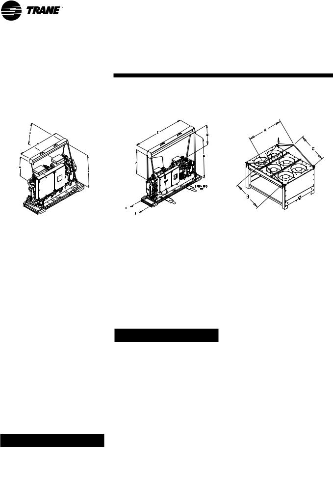
Figure 2- Rigging the unit - RTUB 207-208 |
Figure 3- Rigging the unit - RTUB 210-224 |
Figure 4- Rigging the unit - RTCA 108-216 |
|
Table 3 - Sling Lengths (mm) for lifting |
|
|
|
|
|
|
|
|
A |
B |
C |
D |
E |
|
|
RTUB unit size |
|
|
|
|
|
|
|
207-208 |
2200 |
3000 |
2600 |
2100 |
- |
|
|
210-211-212 |
2400 |
3000 |
2550 |
3150 |
3650 |
|
|
214-216-217 |
2500 |
3000 |
2550 |
3150 |
3650 |
|
|
218-220 |
2450 |
3050 |
2600 |
3150 |
3650 |
|
222-224 |
2450 |
3100 |
2650 |
3150 |
3650 |
|
|
|
RTCA unit size |
|
|
|
|
|
|
|
108/109/111/208/209/211 |
2240 |
1700 |
1700 |
- |
- |
|
113/115/115/213/215/216 |
2240 |
2800 |
2800 |
- |
- |
|
|
|
|
|
|
|
|
|
|
Special Lifting and Moving Instructions
A specific lifting method is recommended as follows:
1.Four lifting points are built into the unit.
2.Slings and spreader bar to be provided by rigger and attached to the four lifting points.
3.Minimum rated lifting capacity (vertical) of each sling and spreader bar shall be no less than the tabulated unit shipping weight.
CAUTION
This unit must be lifted with the utmost care. Avoid shock load by lifting slowly and evenly.
WARNING
To prevent any damage, position the lifting bar so that the slings do not touch the unit.
Isolation
The most effective form of isolation is to locate the unit away from any sound-sensitive area. Structurally transmitted sound can be reduced by elastomeric vibration eliminators. Spring isolators are not recommended for units equipped with helical rotary compressors. Consult an acoustical engineer in critical sound applications. For maximum isolation effect, isolate water lines and electrical conduit. Wall sleeves and rubberisolated piping hangers can be used to reduce the sound transmitted through water piping.To reduce the sound transmitted through electrical
conduit, use flexible electrical conduit. State and local codes on sound emissions should always be considered.
Foundation
Provide rigid, non-warping mounting pads or a concrete foundation of sufficient strength and mass to support the unit's operating weight (that is, including completed piping, and full operating charges of refrigerant, oil, and water). After it is in place, the unit must be level within 1/4" [6 mm] over its length and width. Use shims if necessary. The manufacturer is not responsible for equipment problems resulting from an improperly designed or constructed foundation.
Note for RTCA:The unit must be positioned so that the airflow through the condensation coils is not hindered by any obstacle.The
10 |
RLC-SVX03A-E4 |
 Loading...