

Page 1
February 2003 MS-SVN004-EN
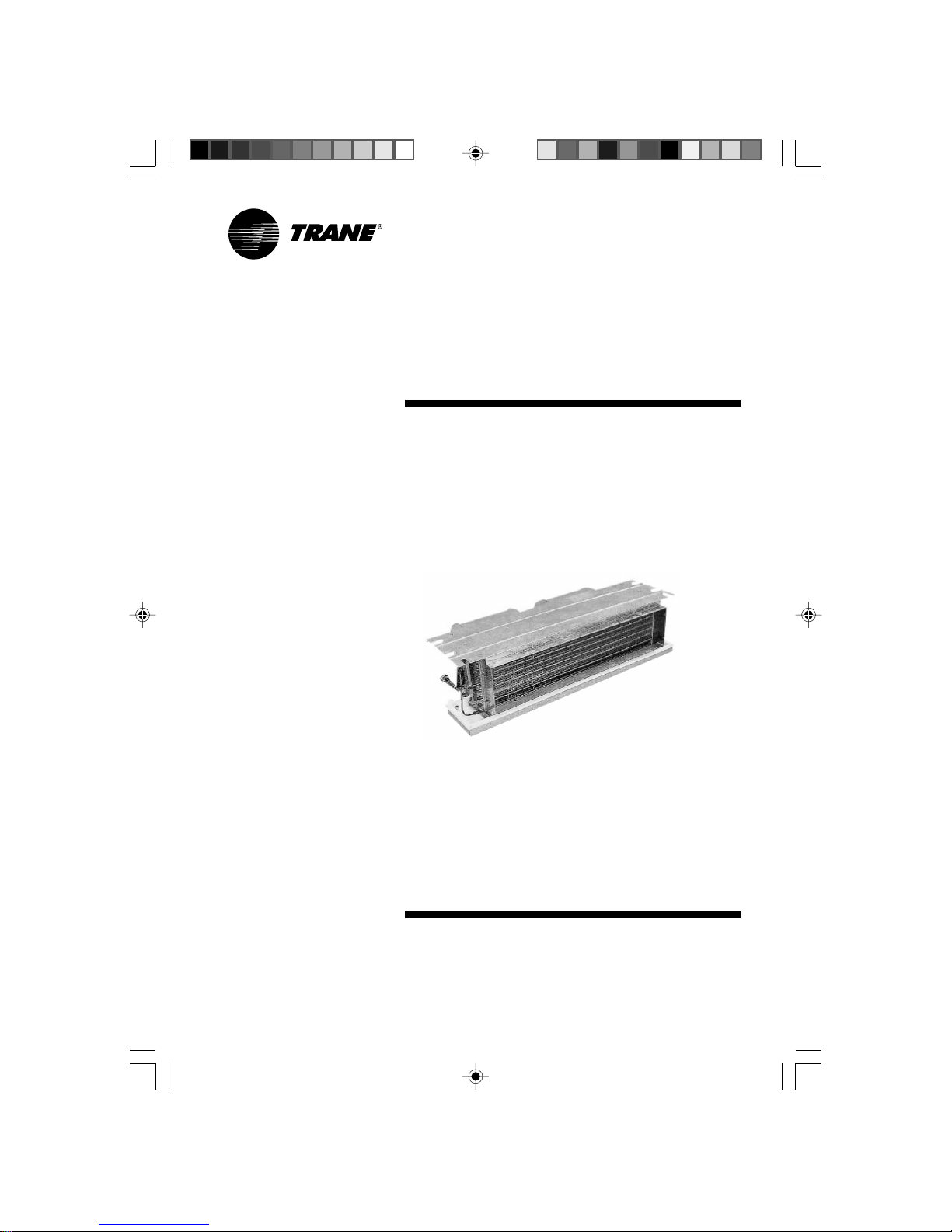
Installation Manual
ILLUSION
Split System
Concealed Type
MCD Series 50/60 Hz
Cooling Only/Cooling Heating
50 Hz Models
MCD 512 DB
MCD 518 DB
MCD 524 DB
MCD 530 DB
MCD 536 DB
MCD 048 DB
MCD 060 DB
Cooling Only/Cooling Heating
60 Hz Models
MCD 512 D1
MCD 518 D1
MCD 524 D1
MCD 530 D1
MCD 536 D1
MCD 048 D1
MCD 060 D1
L/O- 02091985TRA 21/4/03, 2:44 PM1
Page 2
General Information
Introduction
This Installation Manual is given as a
guide to good practice in the
installation by the installer of MCD
mini-split system. Installation
procedures should be performed in
the sequence that they appear in this
manual.
For installing the unit to operate
properly and reliably, it must be
installed in accordance with these
instructions. Also, the services of a
qualified service technician should be
employed, through the maintenance
contract with a reputable service
company.
Read these installation instructions
completely before installing the
air conditioning system.
About the Unit
These MCD units are assembled,
pressure tested, dehydrated, charged
and run tested before shipment.
The information contained in this
manual applies to MCD units are
designed to operate in cooling mode
only and in cooling or heating
modes.
Important
This document is customer property
and is to remain with unit. Please
place in service information pack upon
completion of work.
These instructions do not cover all
variations in systems, nor do they
provide for every possible contingency
to be met in connection with
installation.
Should further information be
desired or should particular
problems arise which are not
covered sufficiently in this manual,
the matter should be referred to
your authorized Trane dealer.
Reception
On arrival, inspect the unit before
signing the delivery note. Specify any
damage of the unit on the delivery
note, and send a registered letter of
protest to the last carrier of the goods
within 72 hours of delivery. Notify the
dealer at the same time.
The unit should be totally inspected
within 7 days of delivery. If any
concealed damage is discovered,
send a registered letter of protest to
the carrier within 7 days of delivery
and notify the dealer.
Warranty
Warranty is based on the general
terms and conditions by country.
The warranty is void if the equipment
is modified or repaired without the
written approval of
The Trane Company, if the
operating limits are exceeded or if
the control system or the electrical
wiring is modified.
Damage due to inappropriate
installation, lack of knowledge or
failure to comply with the
manufacturer’s instructions, is not
covered by the warranty obligation.
If the installation does not conform to
the rules described in Installation
Manual, it may entail cancellation of
warranty and liabilities by
The Trane Company.
About this Manual
Cautions appear at appropriate places
in this Installation Manual.
Your personal safety and the
proper operation of this machine
require that you follow them
carefully.
The Trane Company assumes no
liability for installations or servicing
performed by unqualified personnel.
All phases of the installation of this air
conditioning system must conform to
all national, provincial, state and local
codes.
Warning
Warnings are provided at appropriate
places in this manual to indicate to
installers, operators and service
personnel of potentially hazardous
situations which, if not avoided,
COULD result in death or serious
injury.
Caution
Cautions are provided at appropriate
places in this manual to indicate to
installers, operators, and service
personnel of potentially hazardous
situations which, if not avoided, MAY
result in minor or moderate injury or
malfunction of the unit.
MS-SVN004-EN© American Standard Inc.2000
L/O- 02091985TRA 21/4/03, 2:44 PM2
Page 3
3MS-SVN004-EN
Contents
General Information 2
System Appearance 4
Location and Preparation of Units 6
Units Installation 7
Connection of Refrigerant Tubing 9
Condensate Drain Piping 10
Electrical Installation 11
Wiring Diagram 12
Dimensional Data 15
Maintenance 18
L/O- 02091985TRA 21/4/03, 2:44 PM3
Page 4
4 MS-SVN004-EN
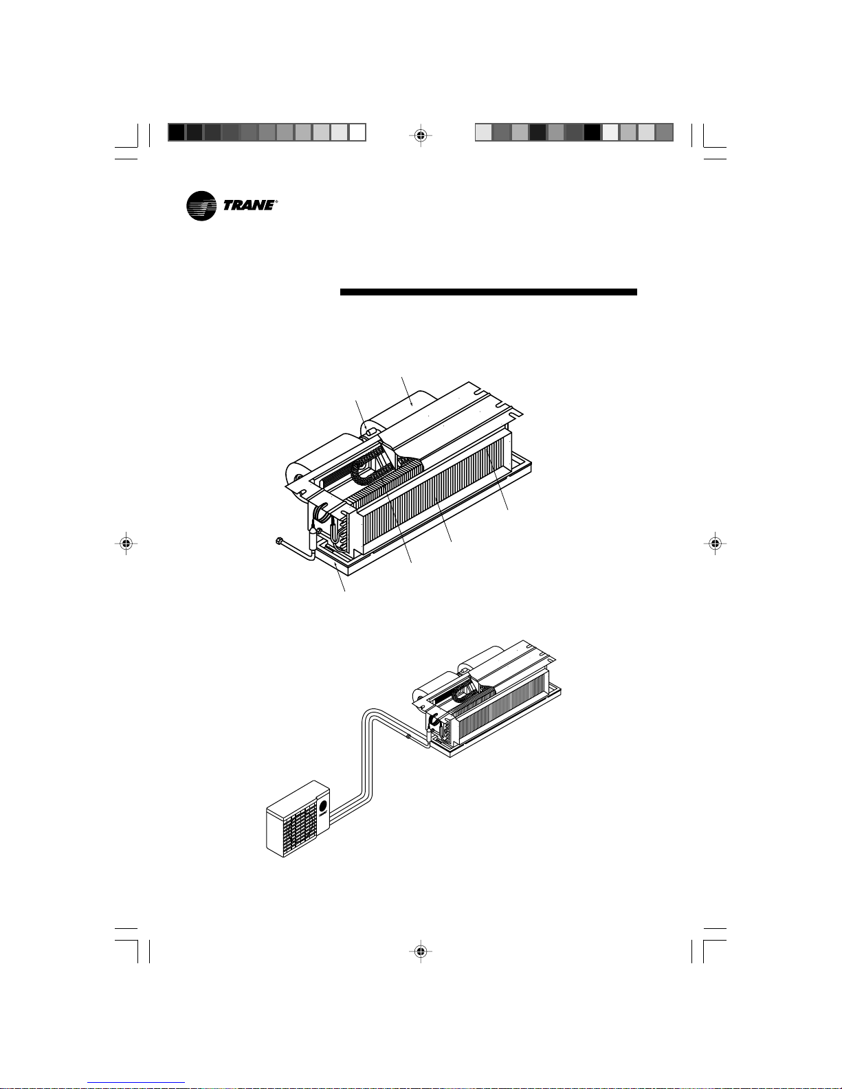
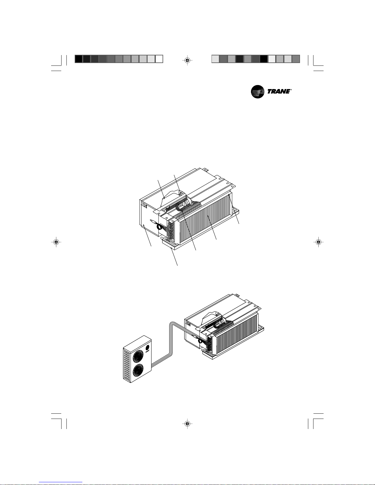
System Appearance
MCD 512-536 DB/D1
Condensate Drain Pan
Electric Heater
(Option)
Evaporator Coil
Outlet Collar
Motor
Blower
Outdoor Unit
Indoor unit
L/O- 02091985TRA 21/4/03, 2:44 PM4
Page 5
5MS-SVN004-EN
MCD 048-060 DB/D1
Blower
Return Air Plenum
(Standard)
Outdoor Unit
Indoor Unit
Electric Heater
(Option)
Condensate Drain Pan
Motor
Evaporator Coil
Outlet Collar
L/O- 02091985TRA 21/4/03, 2:44 PM5
Page 6
6 MS-SVN004-EN
Location and Preparation of Units
Indoor Unit
1. Select a convenient location that
allows the air to reach every corner
of the room and where it is easy to
route the refrigerant tubing, wiring
and drain to the outside.
2. The ceiling construction should be
strong enough to support the
weight of the unit.
3. The refrigerant tubing, drain piping
and wiring conduit are connected
through the wall.
4. Refrigerant tubes between the
indoor and the outdoor units and
drain pipes should be as short as
possible (Figure 1).
5. If a refrigerant charge adjustment is
necessary, follow the Installation
Manual for the Outdoor Unit.
Outdoor Unit
See instructions for location and
preparation of the unit in the Installation
Manual for the Outdoor Unit.
Installation Method:
Indoor Unit
After selecting the location to place
the unit, follow these steps:
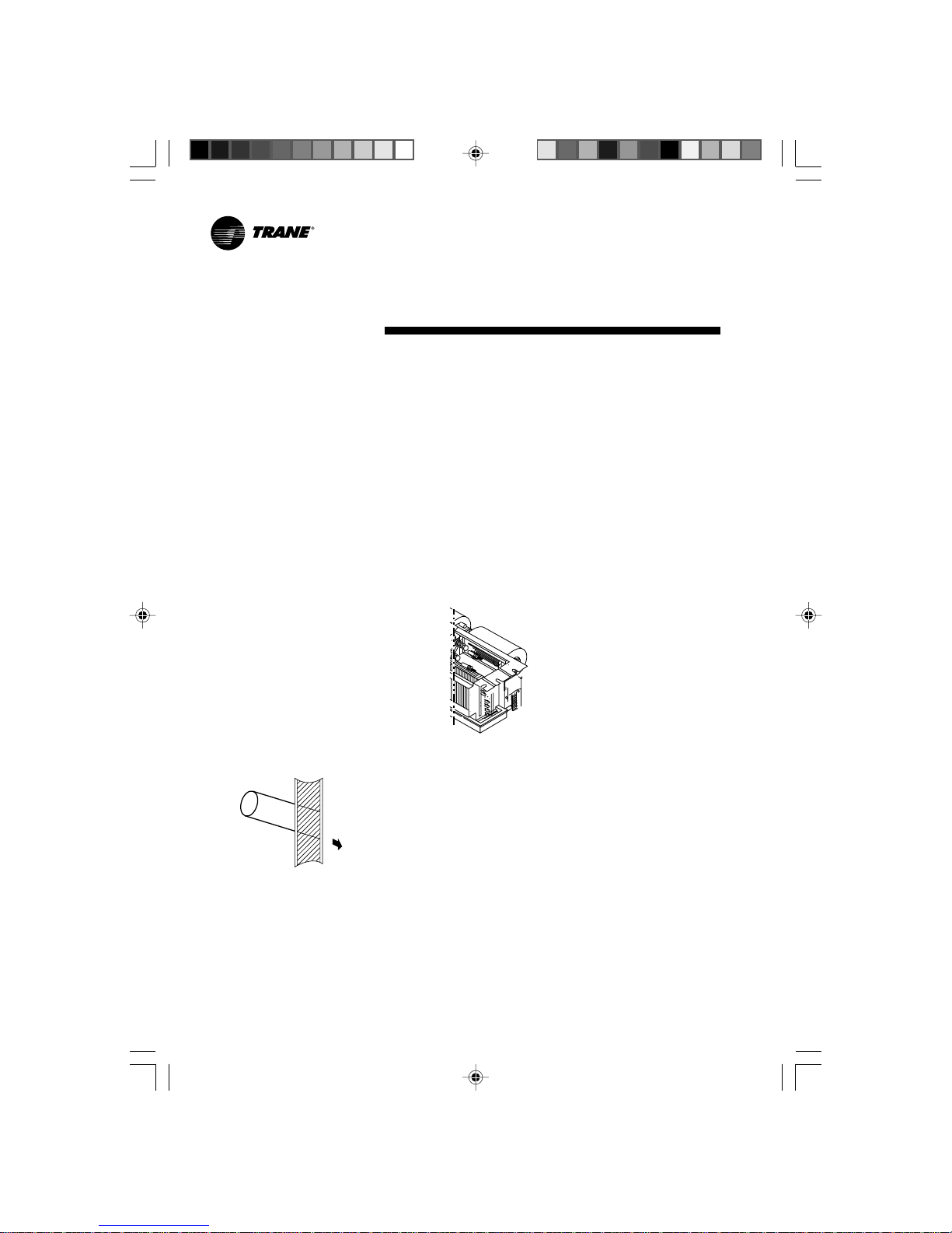
1. Make a hole in the wall to route
tubing and wiring through a locally
purchased PVC pipe. The hole
should slope downwards slightly,
towards the outside (Figure 2).
Figure 1
2. Before cutting, check that no pipes
or studs are directly behind the
place to be cut. Avoid areas where
electrical wiring or conduits are
located.
3. Hang the unit on a solid and level
roof. Noise, vibration or leakage
could occur on and unstable
foundation (Figure 3,4).
For correct installation of duct
work see (Figure 6).
4. Support the unit solidly.
5. To have access to electrical
terminals, remove the right side
junction box (Figure 2).
6. Note that refrigerant tubing,
interconnecting wiring and drain
hose should go through the wall.
Shape these items so that they will
easily fit through the wall.
Figure 2
Outdoor Unit
See the proper installation method
provided in the Installation Manual
for the Outdoor Unit.
Installation Requirements
Important
- Read the Installation Manual
completely before installing and
operating the system.
-Turn on the mains power at least
five (5) hours before operating
the system.
Installation Requirements
Following is a brief outline of where
and how to install the unit. Please read
over the entire set of instructions for
indoor and outdoor units and make
sure all accessory parts list are with
the unit before beginning.
1. Tools Required for Installation
(not supplied)
- Level
- Hole saw or saw
- Core bits
- Hammer
- Drill
-Torque wrench
- Adjustable wrench
- Standard screwdriver
- Phillips head screwdriver
- Knife or wire stripper
-Tape measure
-4 Anchor bolts for ceiling
mounting
2. Refrigerant Piping and Insulation
Material
- See the Installation Manual
included with the Outdoor Unit.
- The length of wiring will determine
the wire size. See local codes and
refer to Section Electrical
Installation.
Caution
Check local electrical codes and
regulations before buying any wire.
Also check for any specitic wiring
instructions or limitations.
3. Additional Materials Required
for Installation
- Saddles or clamps to secure
refrigerant tubing.
- Insulated clamps or staples for
connecting wire. See local codes.
- Ceiling mount: Use nuts and bolts
as required to mount the unit on the
ceiling. Use 4 (3/8) fasteners or
closest standard metric with nuts
and lock washers. The length will
vary with application.
- Refrigerant oil and tape
(insulation).
- Putty or similar filler.
L/O- 02091985TRA 21/4/03, 2:44 PM6
Page 7

7MS-SVN004-EN
J
K
F
E
E
H
G
C
D
D
A
B
K
Min.750 Min. 800 100 150 50 200 Min. 100 Min. 50Min. 200 Min. 300 Min. 300
NOTE: FOR DUCT LENGTH PLEASE SEE PAGE 15, 16 AND 17
IJHABCDEFG
DISTANCE (M.M.)
I
CELING
WALL
DRAIN PIPE
DRAIN PIPE
RETURN PLENUM
WITH FILTER
DETAIL "X"
FLEXIBLE CONNECTER
CHAMBER
CHAMBER
FILTER
FILTER
RETURN AIR GRILLE
SLANT 1 : 50
SUPPLY
DUCT
SUPPLY DUCT
FIGURE 3 (SIDE VIEW)
FIGURE 4 (TOP VIEW)
Unit Installation
L/O- 02091985TRA 21/4/03, 2:44 PM7
Page 8

8 MS-SVN004-EN
Units Installation
6
L/O- 02091985TRA 21/4/03, 2:44 PM8
Page 9

9MS-SVN004-EN
Connection of Refrigerant Tubing
Proper installation prodecure is
recommended in the Installation
Manual Package, usually provided
together with the outdoor unit. It is
advisable to read bofore installing.
The indoor unit refrigerant connections
are located on the left hand side when
facing the unit (Figure 7).
Figure 7
Connecting the Units with
Flaring Procedure.
1. Cut the copper tube to the required
length with a tube cutter. It is
recommended to cut approx.
20-30 cm. longer than the tubing
length.
2. Remove burrs at the end of the
copper tube with a tube reamer
or file, as shown in Figure 8.
Figure 8
Copper
Tubing
Reamer
When reaming, hold the tube end
downward and be sure that no copper
scraps fall into the tube (Figure 9).
Deburring
Before
After
Figure 9
3. Remove the flare nut from the unit
and be sure to insert on the copper
tube.
4. Make a flare at the end of the copper
tube with a flare tool (Figure 10).
Flare Nut
Copper Tubing
Flare Tool
Figure 10
A good flare should have the
following characteristics:
• Inside surface is glossy and smooth.
• Edge is smooth.
•Tapered sides are of uniform
length.
Cautions Before Connecting
Tightly
1. Be sure to apply a sealing cap or
water-proof tape to prevent dust or
water from getting into the tubes
before they are used.
2. Be sure to apply refrigerant
lubricant to the matching surfaces
of the flare and union before
connecting them together. This is
effective for reducing gas leaks
(Figure 11).
Figure 11
Apply refrigerant lubricant here
3. For proper connection, align the
union tube and flare tube straight
with each other, then screw in the
flare nut lightly at first to obtain a
smooth match (Figure 12).
Union Flare Nut
Figure 12
4. Tighten the flare nuts, using the
appropriate wrench.
Connecting the Unit with
Brazing Prodecure
1. Cut the copper tube to the required
length with a tube cutter. It is
recommended to cut approx.
20-30 cm. longer than the tube length.
2. Remove burrs at the end of the
copper tube with a tube reamer
(Figure 8).
3. There are 2 ways to connect the
copper tube
- Use a coupling between the
copper tube of Fan Coil Unit and
the copper tube used for
installation (Figure 13).
Copper Tube
of Fan Coil
Unit
Solder Coupling
Copper Tube of
Condensing Unit
Figure 13
- Expand the copper tube by
using a swaging tool set as in
Figure 14.
Swaging Tool
Tube Holder
(Clamp)
Copper Tube
Figure 14
4. To braze the copper tube, before
brazing a copper tube to a solder
coupling or a copper tube to an
expanded tube, do not forget to
keep them tight as shown in
Figure 15.
COMMET 3
Torch
Solder Coupling
Copper Tube from
Condensing Unit
Solder Rod
Figure 15
Copper Tube
from Fan
Coil Unit
L/O- 02091985TRA 21/4/03, 2:44 PM9
Page 10

10 MS-SVN004-EN
Condensate Drain Piping
Condensate Drain Piping
1. The drain hose should run straight
down the wall to a level where the
run off will not stain the wall.
2. These should have water traps.
Avoid putting the end of the hose in
water.
3. To conveniently drain the system,
the drain piping must slant
downward, with a slope of at least
1:50 to prevent leakage.
4. When the drain hose is placed in
the room, insulate the hose with
foam polyethylene to avoid damage
to the ceiling or furniture.
5. After completing installation of
refrigerant lines, wiring and drain
connections, bind the tubing,
wiring and drain piping (check if
local codes permit binding) into a
bundle by using tape at 100 or 200
mm (4" to 8") intervals. Make sure
the drain tube is at the bottom of
the bundle (Figure 16).
Figure 16
P.V.C.
Conduit
Control Wiring
Power Wiring with
Ground Wiring
Suction Line Tube
Insulation Tube
P.V.C. Tape
Liquid Line Tube
Water Condensated
Drain Tube
(P.V.C. Tube)
L/O- 02091985TRA 21/4/03, 2:44 PM10
Page 11

11MS-SVN004-EN
Electrical Installation
Electrical Installation
All wiring and grounding must comply
with local electrical codes.
Wiring Important Safeguards:
- Check the unit nameplate for
electrical rating. Be sure wiring is
done according to local codes and
wiring diagram.
- Use a separate power line with
circuit breaker for each air
conditioning unit.
- Connect electrical ground to all
units.
- Wiring should not touch refrigerant
tubing, compressor, motors or
moving parts.
- The manufacturer will accept no
responsibility for problems caused
by unauthorized changes in the
internal wiring.
- Connect the wiring firmly.
Indoor Unit
Remove the right side junction box
(see previous instructions) to access
the terminal base.
System Wiring Routing
- Pass the system wiring through the
PVC pipe, referred to in the Section
of Installation Method (both power
and control lines) to interconnect
indoor and outdoor units.
- Connect the wire terminals to the
terminal base. See connection
indication on system wiring
diagram.
- Make sure all connections are tight.
Outdoor Unit
See the electrical installation
instructions in the Installation Manual
for the Outdoor Unit.
L/O- 02091985TRA 21/4/03, 2:44 PM11
Page 12

12 MS-SVN004-EN
Wiring Diagram
CONCEALED FAN COIL UNITS
COOLING ONLY
MCD 512-536 DB/D1
MCD 048-060 DB/D1
Remove HI-BR wire from TB-1 and replace
with EXTRA HI-BLK wire when high speed/cfm
is required in the field.
EXTRA–HI
BLK
HI
MED
LOW
COM
BR
BL
RD
WH
BLOWER
MOTOR
1
2
3
4
L2 L1 C1 C2
THERMOSTAT
3 SPEED SWITCH
POWER SUPPLY
200-240V/1PH/60Hz
220-240V/1PH/50Hz
200-240 VAC
CONTROL WIRING
TO CONDENSING
UNIT.
NOTE :
1. Power wiring and grounding of equipment
must comply with local codes.
2. Ensure that power supply agrees with
equipment nameplate.
3. Use only copper conductors.
LEGEND :
FIELD WIRING
FACTORY WIRING
LOW MEDHI
L/O- 02091985TRA 21/4/03, 2:44 PM12
Page 13

13MS-SVN004-EN
CONCEALED DX AIR HANDLER
COOLING-HEATING
MCD 512-524 DB/D1
EXTRA–HI
BLK
HI
MED
LOW
COM
BR
BL
RD
WH
BLOWER
MOTOR
BLK
RD
RD
1
2
3
4
5
6
REMOVE HI-BR WIRE FROM TB-1 AND REPLACE
WITH EXTRA HI-BLK WIRE WHEN HI SPEED/CFM
IS REQUIRED IN THE FIELD.
HEATER THERMAL OVERLOAD
PROTECTOR (MANUAL RESET)
(MAX.20AMP. NON-INDUCTIVE
FULL LOAD CURRENT)
HEATER THERMAL OVERLOAD
PROTECTOR (AUTO RESET)
(MAX.20AMP. NON-INDUCTIVE
FULL LOAD CURRENT)
HEATER
HC HC
10
2468
HEAT
COOL
TO HEATING
TO COOLING
THERMOSTAT
COOLING-HEATING
SWITCH
3 SPEED
SWITCH
h
OFF
LOWMED HI
POWER SUPPLY
200-240V/1PH/60Hz
220-240V/1PH/50Hz
200-240 VAC
CONTROL WIRING
TO CONDENSING UNIT.
LEGEND:
FIELD WIRING
FACTORY WIRING
1. POWER WIRING AND GROUDING OF
EQUIPMENT MUST COMPLY WITH LOCAL
CODE.
2. ENSURE THAT POWER SUPPLY AGREES
WITH EQUIPMENT NAME PLATE.
3. USE ONLY COPPER CONDUCTORS.
NOTE:
LNC1C2
Wiring Diagram
L/O- 02091985TRA 21/4/03, 2:44 PM13
Page 14

14 MS-SVN004-EN
CONCEALED FAN COIL UNITS
COOLING-HEATING
MCD 530-536 DB/D1
MCD 048-060 DB/D1
Wiring Diagram
C
C
H
H
HEATER
HEATER
CH
HC
NOTES :
THERMOSTAT
3 SPEED
SWITCH
1. POWER WIRING AND GROUDING OF
EQUIPMENT MUST COMPLY WITH
LOCAL CODES.
2. ENSURE THAT POWER SUPPLY
AGREES WITH EQUIPMENT NAME
PLATE.
3. USE ONLY COPPER CONDUCTORS.
HEATER THERMAL OVERLOAD
PROTECTOR (MANUAL RESET)
(MAX.20AMP. NON-INDUCTIVE
FULL LOAD CURRENT)
HEATER THERMAL OVERLOAD
PROTECTOR (AUTO RESET)
(MAX.20AMP. NON-INDUCTIVE
FULL LOAD CURRENT)
FIELD WIRING
FACTORY WIRING
COOLING - HEATING
LEGEND :
MOTOR
BLOWER
EXTRA-HI
RD
RD
WH
LOW
COM
BLK
MED
HI
RD
BL
BR
BLK
TO HEATING
TO COOLING
COOL
SWITCH
h
HEAT
OFF
LOW MED HI
LNC1
5
2 4
6 8
0 1
6
4
3
2
1
C2
POWER SUPPLY
200-240V/1pH/60Hz
220-240V/1pH/50Hz
200-240 VAC
CONTROL WIRING
TO CONDENSING UNIT.
Remove HI-BR wire FROM TB-1 and replace
with EXTRA HI-BLK wire when high speed/cfm
is required in the field.
L/O- 02091985TRA 21/4/03, 2:44 PM14
Page 15

15MS-SVN004-EN
Dimensional Data
Model
MCD 536
MCD 518
MCD 524
MCD 530
MCD 512
External Dimensions (No Plenum)
Refrig. Line Conn. Size Number OfAll External Dimensions are in inch (mm.)
AB CSuction Liquid Fan(s) Motor(s)
2
2
2
2
2
1
1
1
1
1
30"(762) 34 3/4"(882) 37 1/4"(946) 1/4"(6.35) 1/2"(12.7)
30"(762) 34 3/4"(882) 37 1/4"(946) 1/4"(6.35) 1/2"(12.7)
36"(914) 40 1/4"(1034) 43 1/4"(1098) 3/8"(9.52) 5/8"(15.87)
30"(762) 34 3/4"(882) 37 1/4"(946) 3/8"(9.52) 5/8"(15.87)
42"(1067) 34 7/8"(1087) 49 1/4"(1251) 3/8"(9.52) 3/4"(19.05)
VIEW "A"
Ø16
32
111127
63.5
HANGER HOLES - X6
SEE VIEW "A"
A
B
C
C
SUCTION CONNECTION
LIQUID CONNECTION
284
252
166
254
17440
DRAIN CONN. Ø22.5 MPT
210
234
Note: From the experience of our Trane technician, based on the design condition, at velocity at supply air grille of 300 ft/min for bedroom and 400
ft/min for office (based on free face area), the length of the air duct should be more than 3 meters.
L/O- 02091985TRA 21/4/03, 2:44 PM15
Page 16

16 MS-SVN004-EN
VIEW "A"
Ø16
32
E
D
111127
63.5
A
B
C
Ø20
HANGER HOLES - X6
SEE VIEW "A"
C
SUCTION CONNECTION
LIQUID CONNECTION
625
490
300
266
17440
DRAIN CONN. Ø22.5 MPT
254
165
External Dimensions (Return Air Plenum is option)
All External Dimensions are in inch (mm.) Refrig. Line Conn. Sizes
AB CD ESuction Liquid Fan(s) Motor(s)
MCD 512
30"(762) 34 3/4"(882) 37 1/4"(946) 30"(762) 33 15/16"(862) 1/4"(6.35) 1/2"(12.7) 2 1
MCD 518 30"(762) 34 3/4"(882) 37 1/4"(946) 30"(762) 33 15/16"(862) 1/4"(6.35) 1/2"(12.7) 2 1
MCD 524 30"(762) 34 3/4"(882) 37 1/4"(946) 30"(762) 33 15/16"(862) 3/8"(9.52) 5/8"(15.87) 2 1
MCD 530 36"(914) 40 1/4"(1034) 43 1/4"(1098)
36"(914) 39 15/16"(1014) 3/8"(9.52) 5/8"(15.87) 2
1
MCD 536 42"(1067) 42 7/8"(1087) 49 1/4"(1251) 42"(1067)
45 15/16"(1167) 3/8"(9.52) 3/4"(19.05) 2 1
Number Of
Model
Note: From the experience of our Trane technician, based on the design condition, at velocity at supply air grille of 300 ft/min for bedroom and 400
ft/min for office (based on free face area), the length of the air duct should be more than 3 meters.
Dimensional Data
L/O- 02091985TRA 21/4/03, 2:44 PM16
Page 17

17MS-SVN004-EN
VIEW "A"
Ø16
32
Ø20
HANGER HOLES - X6
SEE VIEW "A"
A
B
C
E
D
111
139
75
SUCTION CONNECTION
408
352
180
30
DRAIN CONN. Ø21 MPT
LIQUID CONNECTION
394
354
615
759
C
ABCDESuction Liquid Fan(s) Motor(s)
MCD048 36.06"(916) 40.70"(1034) 43.58"(1107) 35.70"(907) 39.88"(1013) 1-1/8"(28.57) 3/8"(9.52) 2 1
MCD060 42.08"(1069) 46.73"(1187) 49.21"(1250) 41.73"(1060) 45.90"(1166) 1-1/8"(28.57) 3/8"(9.52) 2 1
External Dimensions (Return Air Plenum is Standard)
All External Dimensions are in inch (mm.) Refrig. Line Conn. Size Number Of
Model
Note: From the experience of our Trane technician, based on the design condition, at velocity at supply air grille of 300 ft/min for bedroom and 400
ft/min for office (based on free face area), the length of the air duct should be more than 3 meters.
Dimensional Data
L/O- 02091985TRA 21/4/03, 2:44 PM17
Page 18

18 MS-SVN004-EN
Regular Maintenance
Be sure to disconnect the power
before inspection or maintenance of
air conditioner.
1. Cleaning the air filter
Air flow is reduced and cooling
efficiency impaired if the filter is
clogged. Be sure to clean the filter
every two weeks during the cooling
season.
1.1 How to remove the air filters
- Loose screws located under
the filter in return air plenum
set.
- Remove air filter frame from
return air plenum set.
1.2 How to clean the air filter.
-Wash away dust from the air
filter with clean water or
vacuum it with an electric
vacuum cleaner.
Note:
Once the air filter is washed,
dry it completely before returning it to
its original position.
After cleaning be sure to return it to its
original position.
Cautions
- Do not wash the air filter in water
that is over 40ºC or it may shrink.
- Do not expose the air filter to fire.
- Do not expose the air filter to direct
sunlight for a long time.
- Clean the air filter more frequently
Figure 8
when the air is very dirty.
Maintenance
L/O- 02091985TRA 21/4/03, 2:44 PM18
Page 19

19MS-SVN004-EN
Notes
L/O- 02091985TRA 21/4/03, 2:44 PM19
Page 20

Literature Order Number MS-SVN004-EN 0200
New MCD-SV1801-EN 0698
Stocking Location Bangkok, Thailand
∫√‘…—∑ ·Õ¡·Õ√å ®”°—¥ 35 À¡Ÿà 8 ∂.ªŸÉ‡®â“¡‘ßæ√“¬ µ.”‚√ß„µâ Õ.æ√–ª√–·¥ß ®.¡ÿ∑√ª√“°“√ 10130
Since The Trane Company has a policy of continuous product and product data improvement,
it reserves the right to change design and specifications without notice.
Trane Thailand
7th Floor, Ploenchit Center Building
2 Sukhumvit Road, Klongtoey
Bangkok 10110
Amair Limited
35 Mu 8, Poochaosamingprai Road
Samrong Tai, Samutprakarn 10130
http://www.trane.com
An American Standard Company
L/O- 02091985TRA 21/4/03, 2:45 PM20
 Loading...