

Page 1
Installation
Operation
Maintenance
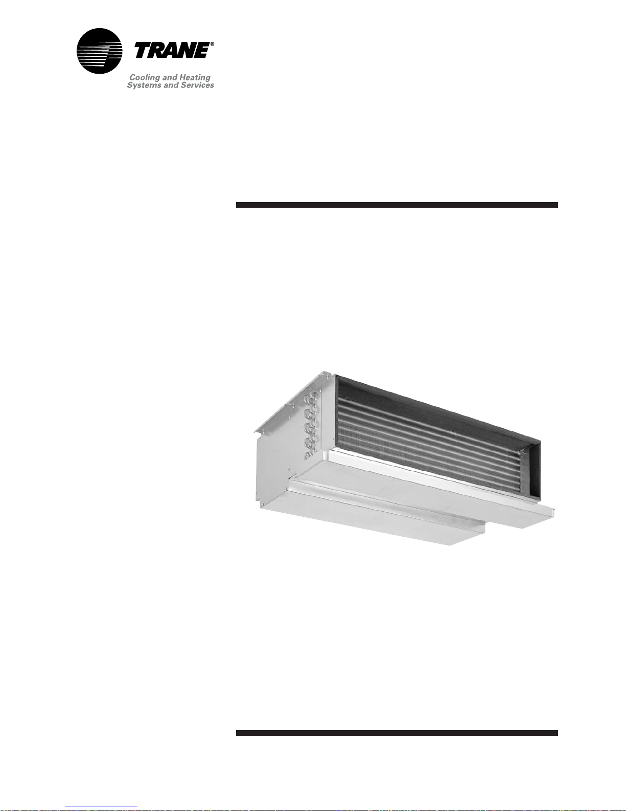
MCD/MWD
512-518-524-530-536-048-060
Ductable ceiling-suspended unit
SS-SVX07B-E4
Page 2
About the unit
MCD/MWD units are assembled,
pressure tested, dehydrated, charged
and run tested before shipment.
MCD units are designed to operate
in cooling mode only, whereas MWD
can operate in cooling or heating
modes. This unit with its mounted
accessories is in conformity with the
provisions of the low voltage
directive 73/23/EEC and
electromagnetic compatibility
directive 89/336/EEC as amended,
and in conformity with nation
implementing legislation.
Reception
On arrival, inspect the unit before
signing the delivery note. Specify
any damage on the delivery note,
and send a registered letter of
protest to the last carrier of the
goods within 72 hours of delivery.
Notify the local sales office at the
same time. The unit should be totally
inspected within 7 days of delivery.
If any concealed damage is
discovered, send a registered letter
of protest to the carrier within 7 days
of delivery and notify the local sales
office. Units are shipped with the
refrigerant operating or holding
charge and should be examined with
an electronic leak detector to
determine the hermetic integrity of
the unit. The refrigerant charge is not
included in the standard Warranty
Cover.
Refrigerant
The refrigerant provided by the
constructor meets all the
requirements of our units. When
using recycled or reprocessed
refrigerant, it is advisable to ensure
its quality is equivalent to that of a
new refrigerant. For this, it is
necessary to have a precise analysis
made by a specialized laboratory. If
this condition is not respected, the
constructor warranty could be
cancelled. Do not release refrigerant
into the atmosphere.
Foreword
These Installation Operation and
Maintenance instructions are given
as a guide to good practice in the
installation, start-up, operation and
periodic maintenance by the user of
MCD/MWD. They do not contain the
full service procedures necessary for
the continued successful operation
of this equipment. The services of a
qualified service technician should
be employed, through the medium
of a maintenance contract with a
reputable service company.
Warranty
Warranty is based on the general
terms and conditions of the
constructor. The warranty is void if
the equipment is modified or
repaired without the written
approval of the constructor, if the
operating limits are exceeded, or if
the control system or the electrical
wiring is modified. Damage due to
misuse, lack of maintenance, or
failure to comply with the
manufacturer's instructions, is not
covered by the warranty obligation.
If the user does not conform to the
rules of chapter "Maintenance", it
may entail cancellation of warranty
and liabilities by the constructor.
About this manual
The information contained in this
manual applies to units designated
MCD/MWD. Cautions appear at
appropriate places in this instruction
manual. Your personal safety and the
proper operation of this machine
require that you follow them
carefully. The constructor assumes
no liability for installations or
servicing performed by unqualified
personnel. Read this manual
carefully and the manual on the
installation of the outdoor unit
before starting to install the system.
© 2008 Trane
SS-SVX07B-E4
General information
Page 3
SS-SVX07B-E4 3
Contents
General information
2 droweroF
2 ytnarraW
2noitamrofni lareneG
2 noitpeceR
2tnaregirfeR
Installation
4gnitrats erofeB
5atad lareneG
31stimil gnitarepO
41gniriw lortnoc dna rewoP
51noitisop noitallatsni fo eciohC
61snoitcennoc tnaregirfeR
81snoitcennoc etasnednoC
81snoitcennoc lacirtcelE
91stcud eht gnitcennoC
91gniretliF
91rellortnoc deriw eht gnillatsnI
Operation
02muucav a gnitaerC
02egrahc tnaregirfer lanoitiddA
12deeps naF
12noitarepo dna noitarugifnoC
12naicinhcet deifilauq a yb pu-trats erofeB
12noitarepo hctiws ycnegreme dna yalpsid tinU
12noitarepo rellortnoc deriW
12noitarepo rellortnoc sseleriW
Maintenance
32ecnanetniam cidoireP
42gnitoohselbuorT
62gnitoohselbuort rellortnoC
82snoitadnemmocer ytefaS
82tcartnoc ecnanetniaM
82gniniarT
Page 4
4 SS-SVX07B-E4
Before starting
Creation of refrigerant lines
To create the refrigerant lines you
will need refrigeration quality
annealed copper tubing. These tubes
are available on the local market
together with the insulation and
mounting equipment. These units
must be connected using screw
connections/flare type for unit sizes
512 to 536 and brazed connections
for unit sizes 048-060.
Electrical connections
Use insulated copper wire. The
section of the core varies depending
on the length required. Refer to
table 1 for the recommended
sections. The wiring and electrical
connections must comply with
national electricity regulations.
Check that the electrical
characteristics on the nameplate
correspond to those of the national
grid. The electrical installation shall
include a disconnect switch in
compliance with local electrical
regulations.
WARNING!
Never open the indoor or outdoor
unit without first disconnecting the
power supply. There is a risk of
electrocution.
Table 1 - Recommended sections of
electric wires (power link)
Unit size Section Maximum fuse size
512 2.5 mm² 16 aM
518 - 524 2.5 mm² 32 aM
530 - 536 RB/SB 4.0 mm² 40 aM
530 - 536 RB/SB 2.5 mm² 32 aM
048 - 060 2.5 mm² 32 aM
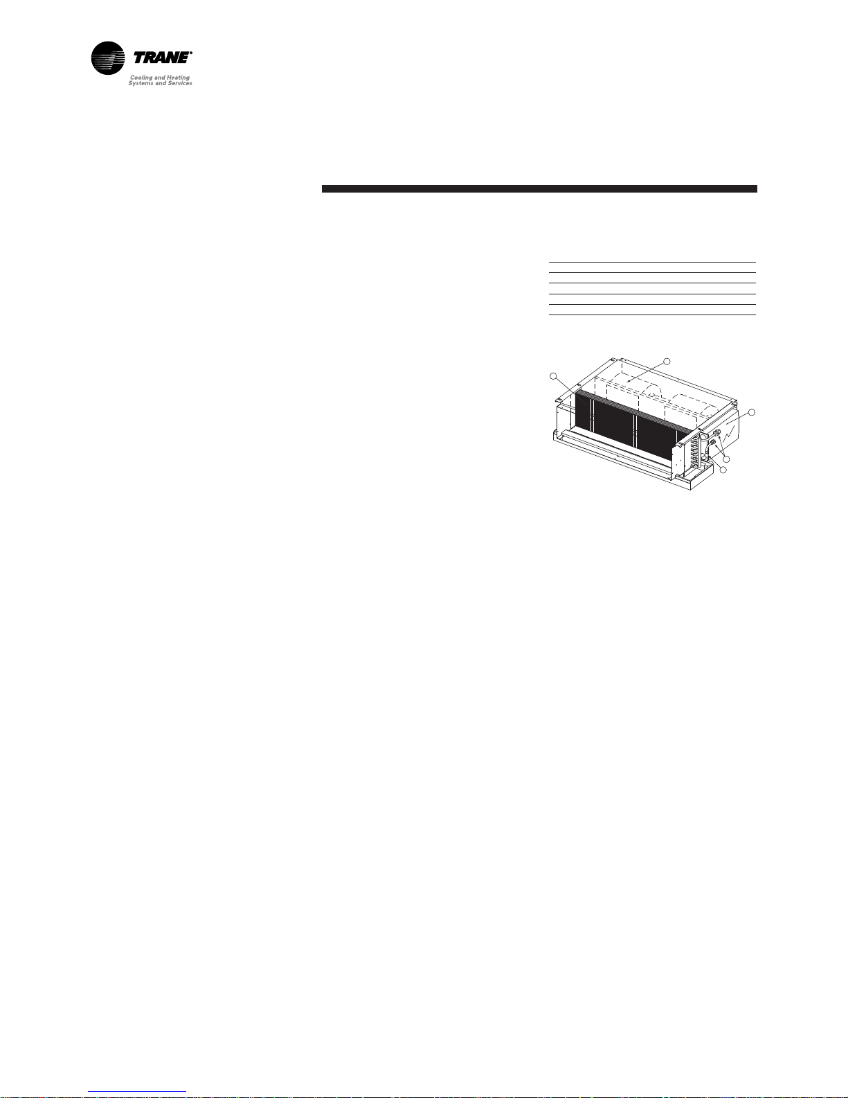
Figure 1 - Unit description
1 = Direct expansion coil
2 = Fan assembly
3 = Control panel
4 = Cooling mode expansion device
(sizes 530-060)
5 = Refrigerant connections
(screw connections/flare type for unit sizes
512 to 536 and brazed connections for unit
sizes 048-060)
▲
1
2
3
5
4
Installation
Page 5
SS-SVX07B-E4 5
Installation
General data
Table 2 - Cooling only R407C (1/2)
Performances TTK 512 RB TTK 518 RB TTK 524 RB TTK 530 SB TTK 530 SC
Indoor unit
MCD 512 CB MCD 518 CB MCD 524 CB MCD 530 CB MCD 530 CB
Cooling Capacity (1) (kW) 3.16 4.56 6.76 8.60 8.60
Power Input (kW) 1.27 1.88 2.87 3.41 3.41
Main Power supply (V/Ph/Hz) 230/1/50 230/1/50 230/1/50 230/1/50 400/3/50
Sound Power Level in high speed (dB(A)) 36 43 40 44 44
Units Amps
Current (A) 6.4 9.6 12.8 19.8 7.7
Starting Amps (A) 28.7 44.0 72.0 97.0 45.5
Recommended Fuse size (AM) type gG 16 20 20 25 20
Recommended Power Wire nb wires x mm23 x 1.5 3 x 2.5 3 x 2.5 3 x 4 4 x 2.5
Recommended Control Interconnection Wire nb wires x mm22 x 1.5 2 x 1.5 2 x 1.5 2 x 1.5 2 x 1.5
Max wire length (2) (m) 50 50 50 50 50
Compressor
Number 11111
Type Rotary Rotary Rotary Scroll Scroll
Model RE 207 VHSMT PE 31 VNEMT NE 41 VNHMT ZR 40 K3E PFJ ZR 40 K3E TFD
Number of speeds 11111
Number of motors 11111
Maximum Continuous Current (A) 6.0 9.0 12.2 18.7 6.6
Locked Rotor Amps (A) 28 43 71 100 46
Motor RPM (rpm) 2850 2900 2900 2900 2900
Crankcase Heater (W) - - - - -
Outdoor Coil
Fin Type Wavy 3B Wavy 3B Wavy 3 B Wavy 3 B Wav y 3B
Tube size (mm) 9.52 9.52 9.52 9.52 9.52
Tube Type Inner Groove Inner Groove Inner Groove Inner Groove Inner Groove
Height (mm) 508 559 559 762 762
Length (mm) 420 755 755 855 855
Face Area (m2) 0.213 0.420 0.420 0.650 0.650
Number of rows 22222
Number of circuits 12244
Fins per feet (fpf) 180 180 180 180 180
Outdoor Fan
Type Axial Axial Axial Axial Axial
Number 11111
Diameter mm (inches) 406(16) 457(18) 457(18) 508(20) 508(20))
Number of speeds 11111
Airflow (3) (4) (m3/h) 1050 2020 2020 3400 3400
Number of motors 11111
Motor (4) (kW) 0.08 0.14 0.14 0.229 0.229
Rated Amps (4) (A) 0.35 0.60 0.60 1.05 1.05
Locked rotor Amps (4) (A) 0.70 1.00 1.00 2.04 2.04
Motor RPM (rpm) 930 930 930 900 900
Capacitor per fan (µF) 2.5 2 2 5 5
Power supply (V/Ph/Hz) 230/1/50 230/1/50 230/1/50 230/1/50 230/1/50
Indoor Fan
Airflow (3) (4) (m3/h) 550 820 1100 1370 1370
Expansion device
Cooling mode Orifice Orifice Orifice Orifice Orifice
Dimensions crated
Length (mm) 672 860 860 1045 1045
Width (mm) 357 340 340 380 380
Height (mm) 577 580 580 790 790
Dimensions uncrated
Length with feet (mm) 667 821 821 1100 1100
Length without feet (mm) 667 821 821 1003 1003
Width with feet (mm) 332 400 400 365 365
Width without feet (mm) 277 327 327 365 365
Height (mm) 517 567 567 790 790
Weight
Weight uncrated (kg) 36 54 58 87 87
Weight crated (kg) 37 56 60 89 89
Refrigerant Connections
Type Flare Flare Flare Flare Flare
Suction line (inches) 1/2 5/8 5/8 3/4 3/4
Liquid line (inches) 1/4 3/8 3/8 3/8 3/8
R407C Refrigerant Charge (kg) 1.1 1.6 2.2 2.5 2.5
Notes:
(1) at 27°C db /19°C wb indoor and 35°C outdoor
(2) Wire channel @ 35°C ambient max.
(3) at nominal airflow with standard drive
(4) for fan system
Page 6
6 SS-SVX07B-E4
Installation
Table 2 - Cooling only R407C (2/2)
Performances TTK 536 SB TTK 536 SC TTK 048 SC TTK 060 SC
Indoor unit
MCD 536 CB MCD 536 CB MCD 048 CB MCD 060 CB
Cooling Capacity (1) (kW) 9.42 9.42 13.14 14.90
Power Input (kW) 4.35 4.35 5.25 6.37
Main Power supply (V/Ph/Hz) 230/1/50 400/3/50 400/3/50 400/3/50
Sound Power Level in high speed (dB(A)) 44 44 53 63
Units Amps
Current (A) 24.6 11.1 11.3 12.7
Starting Amps (A) 116.0 52.0 64.0 72.5
Recommended Fuse size (AM) type gG 40 20 20 20
Recommended Power Wire nb wires x mm23 x 6 4 x 2.5 4 x 2.5 4 x 2.5
Recommended Control Interconnection Wire nb wires x mm22 x 1.5 2 x 1.5 2 x 1.5 2 x 1.5
Max wire length (2) (m) 50 50 50 50
Compressor
Number 1111
Type Scroll Scroll Scroll Scroll
Model ZR 48 K3E PFJ ZR 48 K3E TFD ZR 61 KCE TFD ZR 72 KCE TFD
Number of speeds 1 1 1 1
Number of motors 1111
Maximum Continuous Current (A) 23.5 10.0 10.0 11.4
Locked Rotor Amps (A) 114 50 65.5 74
Motor RPM (rpm) 2900 2900 2900 2900
Crankcase Heater (W) - - - -
Outdoor Coil
Fin Type Wavy 3B Wavy 3B Wav y 3B Wavy 3B
Tube size (mm) 9.52 9.52 9.52 9.52
Tube Type Inner Groove Inner Groove Inner Groove Inner Groove
Height (mm) 762 762 1219 1219
Length (mm) 855 855 855 855
Face Area (m2) 0.650 0.650 1.048 1.048
Number of rows 2222
Number of circuits 4466
Fins per feet (fpf) 180 180 240 240
Outdoor Fan
Type Axial Axial Axial Axial
Number 1122
Diameter mm (inches) 508(20) 508(20) 457(18) 457(18)
Number of speeds 1111
Airflow (3) (4) (m3/h) 3400 3400 4600 4600
Number of motors 1122
Motor (4) (kW) 0.229 0.229 0.29 0.29
Rated Amps (4) (A) 1.05 1.05 1.20 1.20
Locked rotor Amps (4) (A) 2.04 2.04 2.00 2.00
Motor RPM (rpm) 900 900 930 930
Capacitor per fan (µF) 5 5 4 4
Power supply (V/Ph/Hz) 230/1/50 230/1/50 230/1/50 230/1/50
Indoor Fan
Airflow (3) (4) (m3/h) 1650 1650 2190 2300
Expansion device
Cooling mode Orifice Orifice Orifice Orifice
Dimensions crated
Length (mm) 1045 1045 1045 1045
Width (mm) 380 380 390 390
Height (mm) 790 790 1389 1389
Dimensions uncrated
Length with feet (mm) 1100 1100 1030 1030
Length without feet (mm) 1003 1003 1030 1030
Width with feet (mm) 365 365 420 420
Width without feet (mm) 365 365 366 366
Height (mm) 790 790 1246 1246
Weight
Weight uncrated (kg) 89 89 105 108
Weight crated (kg) 91 91 108 111
Refrigerant Connections
Type Flare Flare Braze Braze
Suction line (inches) 3/4 3/4 1 1/8 1 1/8
Liquid line (inches) 3/8 3/8 3/8 3/8
R407C Refrigerant Charge (kg) 2.5 2.5 3.8 4.2
Notes:
(1) at 27°C db /19°C wb indoor and 35°C outdoor
(2) Wire channel @ 35°C ambient max.
(3) at nominal airflow with standard drive
(4) for fan system
Page 7
SS-SVX07B-E4 7
Installation
Table 3 - Cooling only R22 (1/2)
Performances TTK 512 RB TTK 518 RB TTK 524 KB TTK 530 KB
Indoor unit
MCD 512 DB MCD 518 DB MCD 524 DB MCD 530 DB
Cooling Capacity (1) (kW) 3.30 5.00 6.40 8.30
Power Input (kW) 1.51 1.62 2.70 3.30
Main Power supply (V/Ph/Hz) 230/1/50 230/1/50 230/1/50 230/1/50
Sound Power Level in high speed (dB(A)) 36 43 40 44
Units Amps
Current (A) 6.0 8.0 11.3 19.1
Starting Amps (A) 28.7 44.0 72.0 97.0
Recommended Fuse size (AM) type gG 16 20 20 25
Recommended Power Wire nb wires x mm
2
3 x 1.5 3 x 2.5 3 x 2.5 3 x 4
Recommended Control Interconnection Wire nb wires x mm
2
2 x 1.5 2 x 1.5 2 x 1.5 2 x 1.5
Max wire length (2) (m) 50 50 50 50
Compressor
Number 11 11
Type Rotary Rotary Rotary Reciprocating
Model RH207 VHAT PH31 VNET CK32K3-PFZ CR37KQ-PFT
Number of speeds 11 11
Number of motors 11 11
Maximum Continuous Current (A) 5.5 7.0 11.0 18.5
Locked Rotor Amps (A) 31 43 75 85.5
Motor RPM (rpm) 2850 2900 2900 2900
Crankcase Heater (W) - - - -
Outdoor Coil
Fin Type Wavy 3B Wavy 3B Wavy 3B Wavy 3B
Tube size (mm) 9.52 10.52 11.52 12.52
Tube Type Inner Groove Inner Groove Inner Groove Inner Groove
Height (mm) 508 559 559 762
Length (mm) 420 755 755 855
Face Area (m2) 0.213 0.420 0.420 0.650
Number of rows 22 22
Number of circuits 24 44
Fins per feet (fpf) 180 180 180 180
Outdoor Fan
Type Axial Axial Axial Axial
Number 11 11
Diameter mm (inches) 406(16) 457(18) 457(18) 508(20)
Number of speeds 11 11
Airflow (3) (4) (m3/h) 1050 2020 2020 3400
Number of motors 11 11
Motor (4) (kW) 0.08 0.14 0.14 0.23
Rated Amps (4) (A) 0.35 0.60 0.60 1.05
Locked rotor Amps (4) (A) 0.70 1.00 1.00 2.04
Motor RPM (rpm) 930 930 930 900
Capacitor per fan (µF) 2.5 2 2 5
Power supply (V/Ph/Hz) 230/1/50 230/1/50 230/1/50 230/1/50
Indoor Fan
Airflow (3) (4) (m3/h) 550 820 1100 1370
Expansion device
Cooling mode Orifice Orifice Orifice Orifice
Dimensions crated
Length (mm) 672 860 860 1045
Width (mm) 357 340 340 380
Height (mm) 577 580 580 790
Dimensions uncrated
Length with feet (mm) 667 821 821 1100
Length without feet (mm) 667 821 821 1003
Width with feet (mm) 332 400 400 365
Width without feet (mm) 277 327 327 365
Height (mm) 517 567 567 790
Weight
Weight uncrated (kg) 36 54 58 87
Weight crated (kg) 37 56 60 89
Refrigerant Connections
Type Flare Flare Flare Flare
Suction line (inches) 1/2 5/8 5/8 3/4
Liquid line (inches) 1/4 3/8 3/8 3/8
R22 Refrigerant Charge (kg) 1.2 1.9 2.5 3.6
Notes:
(1) at 27°C db /19°C wb indoor and 35°C outdoor
(2) Wire channel @ 35°C ambient max.
(3) at nominal airflow with standard drive
(4) for fan system
Page 8
8 SS-SVX07B-E4
Installation
Table 3 - Cooling only R22 (2/2)
Performances TTK 536 KB TTK 048 KC TTK 060 KC
Indoor unit
MCD 536 DB MCD 048 DB MCD 060 DB
Cooling Capacity (1) (kW) 9.90 13.50 15.80
Power Input (kW) 4.20 5.10 5.90
Main Power supply (V/Ph/Hz) 230/1/50 400/3/50 400/3/50
Sound Power Level in high speed (dB(A)) 44 53 63
Units Amps
Current (A) 21.9 9.0 10.6
Starting Amps (A) 116.0 64.0 72.5
Recommended Fuse size (AM) type gG 40 20 20
Recommended Power Wire nb wires x mm
2
3 x 6 4 x 2.5 4 x 2.5
Recommended Control Interconnection Wire nb wires x mm
2
2 x 1.5 2 x 1.5 2 x 1.5
Max wire length (2) (m) 50 50 50
Compressor
Number 111
Type Reciprocating Reciprocating Reciprocating
Model CR47KQ-PFZ CRPQ-0450-TFD CRNQ-0500-TFD
Number of speeds 111
Number of motors 111
Maximum Continuous Current (A) 21.0 8.0 10.0
Locked Rotor Amps (A) 105 55 65
Motor RPM (rpm) 2900 2900 2900
Crankcase Heater (W) - 27 27
Outdoor Coil
Fin Type Wavy 3B Wavy 3B Wavy 3B
Tube size (mm) 13.52 14.52 15.52
Tube Type Inner Groove Inner Groove Inner Groove
Height (mm) 762 1219 1219
Length (mm) 855 855 855
Face Area (m2) 0.650 1.048 1.048
Number of rows 222
Number of circuits 466
Fins per feet (fpf) 180 240 240
Outdoor Fan
Type Axial Axial Axial
Number 122
Diameter mm (inches) 508(20) 457(18) 457(18)
Number of speeds 111
Airflow (3) (4) (m3/h) 3400 4600 4600
Number of motors 122
Motor (4) (kW) 0.23 0.29 0.29
Rated Amps (4) (A) 1.05 1.20 1.20
Locked rotor Amps (4) (A) 2.04 2.00 2.00
Motor RPM (rpm) 900 930 930
Capacitor per fan (µF) 5 4 4
Power supply (V/Ph/Hz) 230/1/50 230/1/50 230/1/50
Indoor Fan
Airflow (3) (4) (m3/h) 1650 2190 2300
Expansion device
Cooling mode Orifice TXV TXV
Dimensions crated
Length (mm) 1045 1045 1045
Width (mm) 380 390 390
Height (mm) 790 1389 1389
Dimensions uncrated
Length with feet (mm) 1100 1030 1030
Length without feet (mm) 1003 1030 1030
Width with feet (mm) 365 420 420
Width without feet (mm) 365 366 366
Height (mm) 790 1246 1246
Weight
Weight uncrated (kg) 89 105 108
Weight crated (kg) 91 108 111
Refrigerant Connections
Type Flare Flare Flare
Suction line (inches) 3/4 1 1/8 1 1/8
Liquid line (inches) 3/8 3/8 3/8
R22 Refrigerant Charge (kg) 3.8 3.5 4.5
Notes:
(1) at 27°C db /19°C wb indoor and 35°C outdoor
(2) Wire channel @ 35°C ambient max.
(3) at nominal airflow with standard drive
(4) for fan system
Page 9
SS-SVX07B-E4 9
Installation
Table 4 - Heat pump R407C (1/2)
Performances TWK 512 RB TWK 518 RB TWK 524 RB TWK 530 SB TWK 530 SC
Indoor unit
MWD 512 CB MWD 518 CB MWD 524 CB MWD 530 CB MWD 530 CB
Cooling Capacity (1) (kW) 2.97 4.28 6.08 7.95 7.95
Cooling mode power input (kW) 1.46 1.54 2.60 3.26 3.26
Heating Capacity (2) (kW) 3.40 4.61 6.78 8.82 8.82
Heating mode power input (kW) 1.16 1.30 2.13 2.83 2.83
Main Power supply (V/Ph/Hz) 230/1/50 230/1/50 230/1/50 230/1/50 400/3/50
Sound Power Level in high speed (dB(A)) 36 43 40 44 44
Units Amps
Current (A) 6.4 9.6 12.8 19.8 7.7
Starting Amps (A) 28.7 44.0 72.0 97.0 45.5
Recommended Fuse size(AM) type gG 16 20 20 25 20
Recommended Power Wire nb wires x mm23 x 1.5 3 x 2.5 3 x 2.5 3 x 4 4 x 2.5
Recommended Control Interconnection Wire nb wires x mm22 x 1.5 2 x 1.5 2 x 1.5 2 x 1.5 2 x 1.5
Max wire length (3) (m) 50 50 50 50 50
Compressor
Number 11 111
Type Rotary Rotary Rotary Scroll Scroll
Model RE 207 VHSMT PE 31 VNEMT NE 41 VNHMT ZR 40 K3E PFJ ZR 40 K3E TFD
Number of speeds 11 111
Number of motors 11 111
Maximum Continuous Current (A) 6.0 9.0 12.2 18.7 6.6
Locked Rotor Amps (A) 28.0 43.0 71.0 100.0 46.0
Motor RPM (rpm) 2850 2900 2900 2900 2900
Crankcase Heater (W) - - - - -
Outdoor Coil
Fin Type Wavy 3B Wavy 3B Wavy 3B Wavy 3B Wav y 3B
Tube size (mm) 9.52 9.52 9.52 9.52 9.52
Tube Type Inner Groove Inner Groove Inner Groove Inner Groove Inner Groove
Height (mm) 508 559 610 762 762
Length (mm) 420 755 855 855 855
Face Area (m2) 0.213 0.420 0.521 0.650 0.650
Number of rows 22 222
Number of circuits 24 233
Fins per feet (fpf) 180 180 240 180 180
Outdoor Fan
Type Axial Axial Axial Axial Axial
Number 11 111
Diameter mm (inches) 406(16) 457(18) 457(18) 508(20) 508(20)
Number of speeds 11 111
Airflow (4) (5) (m3/h) 1050 2020 2020 3400 3400
Number of motors 11 111
Motor (5) (kW) 0.08 0.14 0.14 0.229 0.229
Rated Amps (5) (A) 0.35 0.60 0.60 1.05 1.05
Locked rotor Amps (5) (A) 0.70 1.00 1.00 2.04 2.04
Motor RPM (rpm) 930 930 930 900 900
Capacitor per fan (µF) 2.5 2 2 5 5
Power supply (V/Ph/Hz) 230/1/50 230/1/50 230/1/50 230/1/50 230/1/50
Indoor Fan
Airflow (3) (4) (m3/h) 550 820 1100 1370 1370
Expansion device
Cooling mode Orifice Orifice Orifice Orifice Orifice
Dimensions crated
Length (mm) 672 860 1045 1045 1045
Width (mm) 357 340 390 380 380
Height (mm) 577 580 695 790 790
Dimensions uncrated
Length with feet (mm) 667 821 1030 1100 1100
Length without feet (mm) 667 821 1030 1003 1003
Width with feet (mm) 332 400 420 365 365
Width without feet (mm) 277 327 366 365 365
Height (mm) 517 567 623 790 790
Weight
Weight uncrated (kg) 36 54 58 87 87
Weight crated (kg) 37 56 60 89 89
Refrigerant Connections
Type Flare Flare Flare Flare Flare
Suction line (inches) 1/2 5/8 5/8 3/4 3/4
Liquid line (inches) 1/4 3/8 3/8 3/8 3/8
R407C Refrigerant Charge (kg) 1.0 1.7 2.3 2.4 2.4
Notes:
(1) at 27°C db /19°C wb indoor and 35°C outdoor
(2) at 7°C db /6°C wb outdoor and 20°C indoor
(3) Wire channel @ 35°C ambient max.
(4) at nominal airflow with standard drive
(5) for fan system
Page 10

10 SS-SVX07B-E4
Installation
Table 4 - Heat pump R407C (2/2)
Performances TWK 536 SB TWK 536 SC TWK 048 SC TWK 060 SC
Indoor unit
MWD 536 CB MWD 536 CB MWD 048 CB MWD 060 CB
Cooling Capacity (1) (kW) 9.05 9.05 11.00 12.40
Cooling mode power input (kW) 3.99 3.99 4.86 5.73
Heating Capacity (2) (kW) 11.20 11.20 13.70 15.30
Heating mode power input (kW) 3.56 3.56 4.38 4.91
Main Power supply (V/Ph/Hz) 230/1/50 400/3/50 400/3/50 400/3/50
Sound Power Level in high speed (dB(A)) 44 44 53 63
Units Amps
Current (A) 6.24.6 11.1 11.3 12.7
Starting Amps (A) 116.0 52.0 64.0 72.5
Recommended Fuse size (AM) type gG 40 20 20 20
Recommended Power Wire nb wires x mm23 x 6 4 x 2.5 4 x 2.5 4 x 2.5
Recommended Control Interconnection Wire nb wires x mm22 x 1.5 2 x 1.5 2 x 1.5 2 x 1.5
Max wire length (3) (m) 50 50 50 50
Compressor
Number 1111
Type Scroll Scroll Scroll Scroll
Model ZR 48 K3E PFJ ZR 48 K3E TFD ZR 61 KCE TFD ZR 72 KCE TFD
Number of speeds 1111
Number of motors 1111
Maximum Continuous Current (A) 23.5 10.0 10.0 11.4
Locked Rotor Amps (A) 114.0 50.0 65.5 74.0
Motor RPM (rpm) 2900 2900 2900 2900
Crankcase Heater (W) - - - -
Outdoor Coil
Fin Type Wavy 3B Wavy 3B Wav y 3B Wavy 3B
Tube size (mm) 9.52 9.52 9.52 9.52
Tube Type Inner Groove Inner Groove Inner Groove Inner Groove
Height (mm) 762 762 1219 1219
Length (mm) 855 855 855 855
Face Area (m2) 0.650 0.650 1.048 1.048
Number of rows 2222
Number of circuits 2244
Fins per feet (fpf) 180 180 240 240
Outdoor Fan
Type Axial Axial Axial Axial
Number 1122
Diameter mm (inches) 508(20) 508(20) 457(18) 457(18)
Number of speeds 1111
Airflow (4) (5) (m3/h) 3400 3400 4600 4600
Number of motors 1122
Motor (5) (kW) 0.229 0.229 0.29 0.29
Rated Amps (5) (A) 1.05 1.05 1.20 1.20
Locked rotor Amps (5) (A) 2.04 2.04 2.00 2.00
Motor RPM (rpm) 900 900 930 930
Capacitor per fan (µF) 5 5 4 4
Power supply (V/Ph/Hz) 230/1/50 230/1/50 230/1/50 230/1/50
Indoor Fan
Airflow (3) (4) (m3/h) 1650 1650 2190 2300
Expansion device
Cooling mode Orifice Orifice Orifice Orifice
Dimensions crated
Length (mm) 1045 1045 1045 1045
Width (mm) 380 380 390 390
Height (mm) 790 790 1389 1389
Dimensions uncrated
Length with feet (mm) 1100 1100 1030 1030
Length without feet (mm) 1003 1003 1030 1030
Width with feet (mm) 365 365 420 420
Width without feet (mm) 365 365 366 366
Height (mm) 790 790 1246 1246
Weight
Weight uncrated (kg) 89 89 105 108
Weight crated (kg) 91 91 108 111
Refrigerant Connections
Type Flare Flare Braze Braze
Suction line (inches) 3/4 3/4 1 1/8 1 1/8
Liquid line (inches) 3/8 3/8 3/8 3/8
R407C Refrigerant Charge (kg) 2.6 2.6 3.3 3.75
Notes:
(1) at 27°C db /19°C wb indoor and 35°C outdoor
(2) at 7°C db /6°C wb outdoor and 20°C indoor
(3) Wire channel @ 35°C ambient max.
(4) at nominal airflow with standard drive
(5) for fan system
Page 11

SS-SVX07B-E4 11
Installation
Table 5 - Heat pump R22 (1/2)
Performances TWK 512 RB TWK 518 RB TWK 524 KB TWK 530 KB
Indoor unit
MWD 512 DB MWD 518 DB MWD 524 DB MWD 530 DB
Cooling Capacity (1) (kW) 3.30 5.00 6.40 8.30
Cooling mode power input (kW) 1.51 1.62 2.70 3.30
Heating Capacity (2) (kW) 3.50 5.90 7.50 9.30
Heating mode power input (kW) 1.20 1.35 2.21 2.92
Main Power supply (V/Ph/Hz) 230/1/50 230/1/50 230/1/50 230/1/50
Sound Power Level in high speed (dB(A)) 36 43 40 44
Units Amps
Current (A) 6.0 8.0 11.3 19.1
Starting Amps (A) 28.7 44.0 72.0 97.0
Recommended Fuse size (AM) type gG 16 20 20 25
Recommended Power Wire nb wires x mm
2
3 x 1.5 3 x 2.5 3 x 2.5 3 x 4
Recommended Control Interconnection Wire nb wires x mm
2
2 x 1.5 2 x 1.5 2 x 1.5 2 x 1.5
Max wire length (2) (m) 50 50 50 50
Compressor
Number 11 11
Type Rotary Rotary Rotary Reciprocating
Model RH207 VHAT PH31 VNET CK32K3-PFZ CR37KQ-PFT
Number of speeds 11 11
Number of motors 11 11
Maximum Continuous Current (A) 5.5 7.0 11.0 18.5
Locked Rotor Amps (A) 31.0 43.0 75.0 85.5
Motor RPM (rpm) 2850 2900 2900 2900
Crankcase Heater (W) - - - -
Outdoor Coil
Fin Type Wavy 3B Wavy 3B Wavy 3B Wavy 3B
Tube size (mm) 9.52 10.52 11.52 12.52
Tube Type Inner Groove Inner Groove Inner Groove Inner Groove
Height (mm) 508 559 559 762
Length (mm) 420 755 755 855
Face Area (m2) 0.213 0.420 0.420 0.650
Number of rows 22 22
Number of circuits 24 44
Fins per feet (fpf) 180 180 180 180
Outdoor Fan
Type Axial Axial Axial Axial
Number 11 11
Diameter mm (inches) 406(16) 457(18) 457(18) 508(20)
Number of speeds 11 11
Airflow (3) (4) (m3/h) 1050 2020 2020 3400
Number of motors 11 11
Motor (4) (kW) 0.08 0.14 0.14 0.23
Rated Amps (4) (A) 0.35 0.60 0.60 1.05
Locked rotor Amps (4) (A) 0.7 1 1 2.04
Motor RPM (rpm) 930 930 930 900
Capacitor per fan (µF) 2.5 2 2 5
Power supply (V/Ph/Hz) 230/1/50 230/1/50 230/1/50 230/1/50
Indoor Fan
Airflow (3) (4) (m3/h) 550 820 1100 1370
Expansion device
Cooling mode Orifice Orifice Orifice Orifice
Dimensions crated
Length (mm) 672 860 860 1045
Width (mm) 357 340 340 380
Height (mm) 577 580 580 790
Dimensions uncrated
Length with feet (mm) 667 821 821 1100
Length without feet (mm) 667 821 821 1003
Width with feet (mm) 332 400 400 365
Width without feet (mm) 277 327 327 365
Height (mm) 517 567 567 790
Weight
Weight uncrated (kg) 36 54 58 87
Weight crated (kg) 37 56 60 89
Refrigerant Connections
Type Flare Flare Flare Flare
Suction line (inches) 1/2 5/8 5/8 3/4
Liquid line (inches) 1/4 3/8 3/8 3/8
R22 Refrigerant Charge (kg) 1.2 1.4 1.7 2.4
Notes:
(1) at 27°C db /19°C wb indoor and 35°C outdoor
(2) at 7°C db /6°C wb outdoor and 20°C indoor
(3) Wire channel @ 35°C ambient max.
(4) at nominal airflow with standard drive
(5) for fan system
Page 12

Installation
12 SS-SVX07B-E4
Table 5 - Heat pump R22 (2/2)
Performances TWK 536 KB TWK 048 KC TWK 060 KC
Indoor unit
MWD 536 DB MWD 048 DB MWD 060 DB
Cooling Capacity (1) (kW) 9.90 13.50 15.80
Cooling mode power input (kW) 4.2 5.10 5.90
Heating Capacity (2) (kW) 11.10 15.10 17.70
Heating mode power input (kW) 3.66 4.45 5.20
Main Power supply (V/Ph/Hz) 230/1/50 400/3/50 400/3/50
Sound Power Level in high speed (dB(A)) 44 53 63
Units Amps
Current (A) 21.9 9.0 10.6
Starting Amps (A) 116.0 64.0 72.5
Recommended Fuse size (AM) type gG 40 20 20
Recommended Power Wire nb wires x mm
2
3 x 6 4 x 2.5 4 x 2.5
Recommended Control Interconnection Wire nb wires x mm
2
2 x 1.5 2 x 1.5 2 x 1.5
Max wire length (2) (m) 50 50 50
Compressor
Number 111
Type Reciprocating Reciprocating Reciprocating
Model CR47KQ-PFZ CRPQ-0450-TFD CRNQ-0500-TFD
Number of speeds 111
Number of motors 111
Maximum Continuous Current (A) 21.0 8.0 10.0
Locked Rotor Amps (A) 105.0 55.0 65.0
Motor RPM (rpm) 2900 2900 2900
Crankcase Heater (W) - 27 27
Outdoor Coil
Fin Type Wavy 3B Wavy 3B Wavy 3B
Tube size (mm) 13.52 14.52 15.52
Tube Type Inner Groove Inner Groove Inner Groove
Height (mm) 762 1219 1219
Length (mm) 855 855 855
Face Area (m2) 0.650 1.048 1.048
Number of rows 222
Number of circuits 466
Fins per feet (fpf) 180 240 240
Outdoor Fan
Type Axial Axial Axial
Number 122
Diameter mm (inches) 508(20) 457(18) 457(18)
Number of speeds 111
Airflow (3) (4) (m3/h) 3400 4600 4600
Number of motors 122
Motor (4) (kW) 0.23 0.29 0.29
Rated Amps (4) (A) 1.05 1.20 1.20
Locked rotor Amps (4) (A) 2.04 2 2
Motor RPM (rpm) 900 930 930
Capacitor per fan (µF) 5 4 4
Power supply (V/Ph/Hz) 230/1/50 230/1/50 230/1/50
Indoor Fan
Airflow (3) (4) (m3/h) 1650 2190 2300
Expansion device
Cooling mode Orifice TXV TXV
Dimensions crated
Length (mm) 1045 1045 1045
Width (mm) 380 390 390
Height (mm) 790 1389 1389
Dimensions uncrated
Length with feet (mm) 1100 1030 1030
Length without feet (mm) 1003 1030 1030
Width with feet (mm) 365 420 420
Width without feet (mm) 365 366 366
Height (mm) 790 1246 1246
Weight
Weight uncrated (kg) 89 105 108
Weight crated (kg) 91 108 111
Refrigerant Connections
Type Flare Flare Flare
Suction line (inches) 3/4 1 1/8 1 1/8
Liquid line (inches) 3/8 3/8 3/8
R22 Refrigerant Charge (kg) 2.6 3.5 4.5
Notes:
(1) at 27°C db /19°C wb indoor and 35°C outdoor
(2) at 7°C db /6°C wb outdoor and 20°C indoor
(3) Wire channel @ 35°C ambient max.
(4) at nominal airflow with standard drive
(5) for fan system
Page 13

SS-SVX07B-E4 13
Installation
Table 6 - Unit dimensions (inch/mm)
ABCDEFGH
MCD/MWD 512 23 (578) 12 (305) 38.5 (980) 31.6 ( 803) 6.7 (170) 3.3 (87) 8.3 (210) 4.3 (110)
MCD/MWD 518 23 (578) 12 (305) 38.5 ( 980) 31.6 ( 803) 6.7 (170) 3.3 (87) 8.3 (210) 4.3 (110)
MCD/MWD 524 23 (578) 12 (305) 42.9 ( 1090) 36.1 (920) 6.7 (170) 3.3 (87) 8.3 (210) 4.3 (110)
MCD/MWD 530 23 (578) 12 (305) 48.3 ( 1228) 42.1 (1069) 6.7 (170) 3.3 (87) 8.3 (210) 4.3 (110)
MCD/MWD 536 23 (578) 12 (305) 48.3 ( 1228) 42.1 (1069) 6.7 (170) 3.3 (87) 8.3 (210) 4.3 (110)
MCD/MWD 048 27.7 (703) 15.4 ( 395) 43 ( 1091) 36 (920) 13.3 (337) 4.2 (110) 12.2 (310) 8.1 (205)
MCD/MWD 060 27.7 (703) 15.4 ( 395) 49 ( 1245) 42.1 (1070) 13.3 (337) 4.2 (110) 12.2 (310) 8.1 (205)
Dimensions
Figure 2 - Unit dimensions
Page 14

14 SS-SVX07B-E4
Installation
Power and control wiring
Table 7 - Control interconnection
Outdoor unit Number of wires x section area (mm²)
Including ground wire
TTK 512 3 x 2.5
TTK 518 2 x 1.5
TTK 524 2 x 1.5
TTK 530 2 x 1.5
TTK 536 2 x 1.5
TTK 048 2 x 1.5
TTK 060 2 x 1.5
TWK 512 5 x 1.5
TWK 518 5 x 1.5
TWK 524 5 x 1.5
TWK 530 6 x 1.5
TWK 536 6 x 1.5
TWK 048 6 x 1.5
TWK 060 6 x 1.5
Table 8 - Power supply outdoor unit (1)
Number of wires x section area (mm²)
Including ground wire
TTK/TWK 512 TTK/TWK 518 3 x 2.5
TTK/TWK 524 3 x 2.5
TTK/TWK 530 4 x 2.5
TTK/TWK 536 4 x 2.5
TTK/TWK 048 4 x 2.5
TTK/TWK 060 4 x 2.5
(1) Indoor and outdoor units are powered separately
(2) Number of wires and section area are given for a
maximum wire length of 50m. If the wire is longer
than 50m, these must be recalculated.
Table 9 - Power supply indoor unit (1)
Without electric heater With electric heater
Number of wires x section area (mm²) Number of wires x section area (mm²)
MCD/MWD 512 3 x 1.5 3 x 2.5 / 3 x 4
MCD/MWD 518 3 x 1.5 3 x 4
MCD/MWD 524 3 x 1.5 3 x 4
MCD/MWD 530 3 x 1.5 4 x 4
MCD/MWD 536 3 x 1.5 4 x 4
MCD/MWD 048 3 x 1.5 4 x 4
MCD/MWD 060 3 x 1.5 4 x 4
(1) Indoor and outdoor units are powered separately
(2) Number of wires and section area are given for a
maximum wire length of 50m. If the wire is longer
than 50m, these must be recalculated.
Page 15

SS-SVX07B-E4 15
Installation
Table 10 - Recommended piping R407C/R22
D3 D2 D1 Line diameter (inches)
Outdoor unit Indoor unit (m) (m) (m) Gas Liquid
TTK/TWK 512 MCD/MWD 512 20 12 15 1/2 1/4
TTK/TWK 518 MCD/MWD 518 24 18 24 5/8 3/8
TTK/TWK 524 MCD/MWD 524 24 18 24 5/8 3/8
TTK/TWK 530 MCD/MWD 530
12 12 12 5/8
3/8
40 18 24 7/8
TTK/TWK 536 MCD/MWD 536
18
18
18 3/4
3/8
40 24 7/8
TTK/TWK 048 MCD/MWD 048
24
18 24
7/8
3/8
40 1 1/8
TTK/TWK 060 MCD/MWD 060
18 12 18 7/8 3/8
40 18 24 1 1/8 1/2
Choice of installation
position
To ensure correct installation, the
following points must be
considered.
- The ceiling must be strong enough
to support the weight of the unit.
- Choose a place where it will be
easy to comply with the
recommended clearances, taking
into account the additional space
required due to external
accessories.
- Take into consideration the drilling
of the holes in the walls to connect
the unit.
- Make sure the maximum distances
between the two units are not
exceeded. See Figure 3 and
Table 10.
Figure 3- Recommended clearances and
maximum lengths used between two
units
Preparing the ceiling and installing
the unit
Drill holes in the ceiling to fix the
threaded rods according to the
dimensions given the Dimensions
section. The angle brackets can also
be used to space the drill holes.
Access is necessary on the
refrigerant connection side to
facilitate installation, maintenance
and access to the cabinet.
Four 8 mm diameter threaded rods
must be securely fixed into the
ceiling. Introduce the other end of
the rods through the slots of the unit
suspension brackets. Position the
shock absorbers, add washers and
screw the nuts down until the unit is
correctly supported. The unit must
be perfectly level in both directions
to ensure correct evacuation of the
condensates. If there is enough
space, a rubber or neoprene sheet
can be placed between the ceiling
and the unit.
Page 16

16 SS-SVX07B-E4
Installation
Refrigerant connections
It is possible to remove the electrical
cabinet to facilitate access to the
refrigerant connection.
Installation procedure
- Make sure the route taken by your
refrigerant lines is as short as
possible.
- Limit pressure losses in the lines
which may be caused by crushing
of the lines, a large number of
bends or bending radii that are too
small.
- Slope all the gas lines leaving the
indoor unit so that oil can return to
the compressor by gravity.
· Prevent any possibility of oil
trapped in the gas lines.
CAUTION!
An insufficiently lubricated
compressor may break down.
If the vertical difference in level
between the units is greater than
2.5 m, an oil trap must be positioned
at the bottom of the vertical line, and
an additional trap must be
positioned every 7.5 m of vertical
elevation to allow oil return to the
compressor. There are no special
technical recommendations for
liquid lines because of the wellbalanced mixture of refrigerant and
oil. Movement of the liquid
refrigerant also causes the oil to
move.
Passage of the tube and cable
bundle
Before drilling into the wall
- make sure there are no pipes or
electrical cables in the wall at the
place where you are going to drill
provide a protective sleeve for the
bundle of tubes and cables at the
point where it passes through the
hole (Figure 4). If permitted by
legislation, the condensate
drainage line can also be included
in the bundle. Wrap tape around
all the lines and cables from the
bottom of the outside unit to the
point where the piping enters the
wall. Carry out the same operation
for each circuit.
Figure 4 - Protective sleeve
A = Cable bundle
1 = Wall
2 = Inside
3 = Outside
A
Page 17

SS-SVX07B-E4 17
Installation
Brazed connections
These lines will be created on the
installation site. They will be
installed according to normal trade
practice by qualified personnel, in
compliance with local legislation.
1. Remove the plugs from the units'
refrigerant connections just before
connecting the piping, when all
the connections on the refrigerant
lines have been terminated. This
will prevent contamination by
humidity. Remove the rubber
plugs from the ends of the tubes.
2.Use a clean dry copper tube for
refrigeration installations.
3.Use silver brazing alloy only. Do
not overheat the welds and carry
out nitrogen scavenging inside the
tubes to prevent oxidization during
brazing.
4.Once all the other connections
have been made, debraze or cut
the plug on the outdoor unit's
refrigerant line connections.
Proceed in the same way as for
brazing of the indoor unit's lines.
Line insulation
To prevent heat losses and
condensation, both liquid and gas
lines must be thoroughly insulated.
Unscrew the Flare nuts which are
placed on the beginnings of the
indoor unit lines. Put the Flare nut
onto the tube. Splay the tube.
Connect the refrigerant tubes to the
indoor unit. Tighten the Flare nuts
using the recommended tightening
torques in Table 11. Insufficient
tightening will cause refrigerant
leaks. Use flat wrenches only (see
Figure 6). Repeat the operation for
each circuit.
Figure 6 - Tightening flare nuts
Table 11 -Recommended tightening
torques
Line diameter Tightening torque (kg/cm)
1/4'' 150-200
3/8'' 350-400
1/2'' 500-550
5/8'' 600-650
3/4'' 700-750
Screw/flare connections
CAUTION!
When cutting, deburring and
splaying the tubes, keep the end of
the tube down to make sure that
copper waste does not fall into the
lines.
Cut the copper tube using a pipecutter only (do not use a metalsaw).
Hold the tube downwards when
deburring it.
Figure 5 - Deburring recommendations
Page 18

18 SS-SVX07B-E4
Installation
Condensate connections
The unit must be perfectly level in
both directions. Connect the indoor
unit's condensate tray to a
condensate drainage line. The unit is
equipped with a 20 mm diameter
smooth tube connection. To ensure
correct condensate flow, the
drainage tube must be given a
10° slope. There must not be a
condensate trap at any point in the
line. However, a trap can be
provided to prevent outside air from
being taken in by the indoor unit. If
the tube enters a room, insulate it to
prevent condensation damage.
Figure 7 - Condensate drainage
connections
Electrical connections
All the wiring and earthing
arrangements must comply with
local legislation.
WARNING!
Never open the indoor or outdoor
unit without first disconnecting the
power supply. There is a risk of
electrocution.
CAUTION!
1. Check the electrical characteristics
on the unit's nameplate. Make
sure the wiring complies with the
manufacturer's electrical diagram
and local legislation.
2. Connect the units using one or
more lines protected by an
electrical disconnect device.
3. Ground each unit.
4. The cables must not touch the
refrigerant lines, the motors or
other moving parts and metal
edges.
5. The manufacturer does not
assume any liability for problems
caused by modifications made to
the unit's internal wiring.
6. Tighten the terminals securely.
7. For the electrical connections,
refer to the interconnection
diagrams attached with the
machine.
Page 19

SS-SVX07B-E4 19
Installation
Connecting the ducts
Units can be equipped with
rectangular discharge and/or intake
from the bottom or intake from the
back ducts.
WARNING!
The pressure loss in the network and
the accessories must not exceed the
unit's available static pressure given
in the selection data. The design and
installation shall be done by a
qualified technician and according to
local regulations.
Figure 8 - Discharge and intake duct
possibilities
A = Discharge
B = Intake from the bottom
C = Intake from the back
Table 12 - Duct connection dimensions
Unit size Length (mm) Height (mm)
512/518 748 198
524/530/536 948 248
048/060 1148 298
Filtering
Filtering the air is necessary to
ensure the unit's correct operation.
The unit is supplied with a filter.
Installing the wired
controller
Location
- Do not install thermostats near or
above a source of heat (i.e. direct
sunlight, hot lamps or radiator).
- Do not expose the controller to the
indoor unit discharge air stream.
- Do not place in a confined space.
Wiring
Electrical interconnection between
units must be in accordance with
national, state and local codes.
Units must be grounded. Refer to
the wiring diagrams that are shipped
with the unit.
Page 20

20 SS-SVX07B-E4
Operation
Creating a vacuum
For this operation, use a pump
capable of creating a vacuum of
1 mm Hg (1.3mbar) or less. To create
the vacuum you must connect the
pump to the Schrader pressure
connection on service valve
A located on the outdoor unit (gas
line). To use the vacuum pump,
follow the pump manufacturer's
instructions. Create a vacuum up to
2 mm Hg (2.6mbar) or less. Once the
value of 2mm Hg or less has been
reached, an increase in pressure will
be observed after a certain time. The
maximum permissible increase is
1 mm Hg after 15 minutes. If the
increase is greater and remains at a
constant value, this means there is
too much humidity in the system.
In this case, break the vacuum using
dry nitrogen and start the vacuum
creation procedure again.
A continuous increase in pressure
means there is a leak in the system.
WARNING!
Valves A and B must not be opened
before the installation of the
refrigerant circuit has been
completely finished, or the
refrigerant charge will be lost.
Figure 9 - Refrigerant circuit
1 = Outdoor unit
2 = Vacuum pump
3 = Indoor unit
4 = Gas line
5 = Liquid line
6 = TTK/TWK cooling mode
Additional refrigerant
charge
Once the system has been vacuum
pumped and is in operation and if
the distance between the units is
greater than 6m, it may be
necessary to add an additional
charge. Table 13 indicates the
amounts of refrigerant to add per
additional meter of line. Once the
appropriate amount of refrigerant
has been added, fully open liquid
line valve and check the operating
pressure.
Figure 10 - Adding refrigerant charge
1 = Outdoor unit
2 = Gas line
3 = Indoor units
4 = Liquid line
5 = For sizes 512 to 524
6 = For sizes 530 to 060
A
R22 Refrigerant
While the unit is operating, charge
the unit with gas through the service
Schraeder valve located at the
compressor suction. R22 refrigerant
can also be added in liquid phase in
the liquid line: see method used for
R407C. Never add liquid in the
suction line of the compressor.
R407C Refrigerant
WARNING! add only R407C
refrigerant in liquid state. Never add
liquid in the suction line of the
compressor period. Use service
Schraeder valve located on the liquid
line to charge the unit. While the unit
is operating, close partially the
service valve in order to create a
lower pressure downstream the
service valve. Add the refrigerant
necessary. Control the added weight
with a scale.
Table 13 - Additional refrigerant charge
Liquid line Gas line Additional
R22/R407C charge (g)
1/4'' 1/2'' 26
5/16" 5/8" 36
3/8'' 5/8'' 60
3/8'' 3/4'' 60
3/8'' 7/8'' 63
3/8'' 1 1/8'' 68
Page 21

SS-SVX07B-E4 21
Operation
Fan speed
Refer to the selection data to select
the static pressure according to the
flow rate. From this it is possible to
deduce a fan rotation speed. Once
you have chosen the speed, refer to
the interconnection diagram to
connect the room thermostat to the
unit electric cabinet in order to
power the correct selected speed.
Configuration and
operation
The unit is equipped with a control
board that manages operation of the
split system. It is fitted with 4
switches, SW1-1 to SW1-4.
Before start-up by a
qualified technician
Once the system has been installed,
it is recommend to carry out the
following checks.
1. Make sure no tools or debris
have been left inside, around or
on top of the unit.
2. Unit is perfectly level in both
directions.
3. Check the electrical connections
have been correctly done. Check
the electric power supply
corresponds to the units'
nameplates.
4. Make sure the disconnect
switches have been disengaged.
5. Check the refrigerant lines are
fixed securely.
6. Check if the condensate drain
pan is correctly installed.
7. Check the piping connections
and the water-tightness of the
connectors using an appropriate
leak detection method. Check
the connections on the site have
been tightened.
8. Make sure the gas piping and
the condensate drainage tube
are insulated properly to prevent
problems with trickling of
condensation water.
9. Check the fan turns freely.
10. Make sure the intake and
discharge ducts are not blocked.
11. Check the filters are correctly
positioned. Show the user how
to change the filters.
12. Power up the system and
observe operation carefully:
make any necessary
adjustments.
13. Explain to the user how to
operate the unit.
Unit display and
emergency switch
operation
Four lamps on the unit display show
operating status. In case of loss of
the remote control unit, the system
can be operated temporarily by the
emergency switch. The emergency
switch changes the system mode of
operation by cycling through the
following modes:
➠ FAN ➠ COOL ➠ HEAT ➠ AUTO ➠
OFF ➠.
COOL, HEAT and AUTO operation
are at fixed setting of 24°C. Fan
speed is controlled by the AUTO
mode. FAN only operation is at
HIGH fan speed.
Figure 11 - Unit display
1 = Remote control receiver - this picks up the
infrared signals from the wireless controller
2 = Fan lamp- lit when the fan is operating
3 = Cooling lamp - lit when the unit is
operating in COOL mode (or COMP ON in
AUTO mode)
4 = Heating lamp - lit when the unit is
operating in HEAT mode (or heater ON in
the HEAT mode of AUTO mode)
5 = Timer lamp - lit when the system is being
controlled by the timer
6 = Emergency switch
Wired controller operation
Figure 12 - Wired controller
1 = Press to turn on or off the unit, passing
through the different modes: OFF à COOL à
HEAT.
2 = Press TEMP + to increase the setting
temperature. Press TEMP - to decrease the
setting temperature. The setting
temperature will blink for 4 seconds, then
the current room temperature will display.
3 = Press to select the required fan speed. The
speed will be shown by LED indicators:
AUTO ➠ HIGH ➠ MEDIUM ➠ LOW ➠
AUTO
HIGH
MED
LOW
HEAT
COOL
POWER FAN
TEMP+
TEMP-
Page 22

22 SS-SVX07B-E4
Operation
Auto (optional)
The unit can be put into 5 different
modes (FAN, COOL, DRY, HEAT and
AUTO). The cycling will be:
➠ FAN ➠ COOL ➠ DRY ➠ HEAT ➠
HEAT ➠AUTO ➠
When the system is in AUTO mode,
the display on the remote controller
will show COOL and HEAT modes at
the same time.
Louver (optional)
To change the angle of the louver: if
the button is pressed and released,
the angle of the louver is changed
one step at a time. If the button is
pressed and held, the angle of the
louver is changed until the button is
released.
Sleep mode
For COOL mode, the setting
temperature will be automatically
raised 1°C after 1 hour. For HEAT
mode, the setting temperature will
be automatically lowered 1°C after 1
hour.
When the system is in SLEEP mode,
pressing the SLEEP button will
cancel the SLEEP function. When
the system is in SLEEP mode,
pressing the TEMP button will raise
the setting temperature 1°C from the
last setting.
When the system is in SLEEP mode
and the unit is stopped by a power
failure or is turned off, the SLEEP
function will be canceled.
Wireless controller
operation
To use the wireless controller, point
the transmitter head directly towards
the unit receiver to emit infrared
signals.
Figure 13 - Wireless controller
1. Operating mode
2. Fan speed
3. Fan button
4. Sleep button
5. Mode button
6. Sweep button - to turn on/off the sweep
motor
7. Louver button
8. Timer (start) button
9. Send button - to transmit all parameters
shown on the LCD to the main control
board
10. Clock
11. Timer (start/stop)
12. Transmit mode (lit when remote is being
used)
13. Sleep mode
14. Temperature (range: 16-30°C)
15. Power button
16. Temperature setting button
17. Stop button
18. Clock setting button
19. Minute setting button
20. Hour setting button
SLEEP MODE
SWEEP LOUVER
HOUR
START
SEND
TEMP
STOP
MIN
FAN
COOL
DRY
HEAT
10:14
18:40
6:30
START
STOP
HIGH
MED
LOW
AUTO
Clock
To set the clock:
- Press the clock setting button
(Figure 13, 18). The time display
will blink.
- Press the HOUR button to set the
hour. (Figure 13, 20)
- Press the MIN button to set the
minutes. (Figure 13, 19)
- Press the clock setting button
again. The time display will stop
blinking.
Auto start
The unit can be programmed to start
automatically. To program:
- Press the START button. (Figure
13, 8) The time display will blink.
- Press the HOUR button to set the
hour. (Figure 13, 20)
- Press the MIN button to set the
minutes. (Figure 13, 19)
- Press the START button again. The
time display will stop blinking.
Auto stop
The unit can be programmed to stop
automatically. To program:
- Press the STOP button. (Figure 13,
17) The time display will blink.
- Press the HOUR button to set the
hour. (Figure 13, 20)
- Press the MIN button to set the
minutes. (Figure 13, 19)
- Press the STOP button again. The
time display will stop blinking.
Page 23

SS-SVX07B-E4 23
Maintenance
WARNING!
Disconnect the unit's power supply
before servicing the unit. When
servicing the units, make sure that
the air passages through the coils
(both internal and external) are
clean, and free of dirt and debris.
Periodic maintenance
CAUTION!
Failure to follow these instructions
may cause damage to the unit. The
frequency of servicing will depend
on the conditions for use of the unit,
and will be determined by regular
inspections.
1. Check the condensate piping is
not blocked.
2. Turn the fan blades manually and
make sure they are not damaged.
Clean them if necessary and
verify their alignment.
3. Motor - check the wiring, and
ensure the commutators are
operating correctly. Replace any
damaged components.
4. Disconnection of power and
electrical components - check for
correct operation.
5. Refrigerant circuit - use an
appropriate leak detection method
to check for leaks.
6. Tighten all the screws and bolts.
7. Make sure that the air passages
through the coils (both internal
and external) are clean, and free
of dirt and debris.
8. Clean the filter by beating it and
applying suction in the opposite
direction to the airflow.
Handling the filter
1. To remove the filter, slightly push
the 4 clips down.
2. Remove the filter.
3. To put the filter back, just clip the
filter back into place
Page 24

24 SS-SVX07B-E4
Maintenance
Table 14 - Troubleshooting
Symptoms Possible causes Checks Corrective action
No cooling or
heating
A. Compressor or fan is not operating.
1. Loose electrical connections. 1. Tighten the connections if necessary.
2. Check the fuses and wiring. 2. Replace the fuses if necessary.
B. The fan is operating but the compressor
does not start.
1. Check the compressor's wiring and
winding resistors.
1. If the check shows the motor windings
are broken or earthed, replace the
compressor.
2. Check the capacitor 2. Replace if necessary.
C. The compressor is operating but the fan
does not start.
1. Check the fan motor, the capacitor or
the wiring.
1. Repair or replace
D. Control switch is defective, incorrectly
wired or adjusted.
1. Check the control switch connections
and the temperature setting.
1. Change the setting. Replace if defective.
Insufficient heating
or cooling
A. Lack of refrigerant fluid. 1. Check there are no leaks. 1. Drain, repair and recharge.
B. Insufficient air volume.
1. Check the air filter. 1. Clean and replace.
2. Check the fin assemblies are clean. 2. Clean if obstructed.
3. Check the fan.
3. If the fan is loose on its shaft, tighten the
fixing bolts.
4. Check the wiring and capacitors. 4. Repair or replace
C. Obstructed capillaries or blocked orifice.
1. Check there is no humidity in the
system.
1. Drain and recharge.
Page 25

SS-SVX07B-E4 25
Maintenance
Symptoms Possible causes Checks Corrective action
The system operates
for too long or
continuously.
A. Control switch no longer responds to the
ambient temperature.
1. Check operation and connections of
the control switch.
1. Replace the control switch if it is defective.
B. Loss of refrigerant fluid. 1. Check there are no leaks in the system. 1. Repair and recharge.
C. Insufficient ventilation.
1. Check the air circulation in the
condenser.
1. Make sure air circulation is satisfactory.
Move the outdoor unit if necessary.
D. Incorrectly adjusted control switch. 1. Check the set point. 1. Adjust or replace if defective.
System operates in
short cycles.
A. Defective control switch 1. Check operation of the control switch. 1. Replace if defective.
B. Insufficient air circulation.
1. Check air circulation in the indoor and
outdoor units.
1. Clean the coil and filter if necessary.
C. Insufficient or excess refrigerant fluid.
1. Check if there are leaks or excess
pressure.
1. Repair if there are leaks. Add or remove
refrigerant fluid.
D. Incorrect electric power supply. 1. Check the electric power supply. 1. Find cause and stabilise the power supply.
Internal coil frozen.
A. Insufficient refrigerant fluid. 1. Check if there are leaks in the system. 1. Repair the leak and recharge.
B. Insufficient air circulation.
1. Check the filter. 1. Clean and put back in position.
2. Check the fin block.
2. Clean the fins. If the filter is missing, install
one.
3. Check the fan.
3. Fan free on the bearing, tighten the fixing
screws - connection fault, find the cause
and repair.
C. Defective anti-frost sensor. 1. Check the sensor. 1. Replace if necessary.
Unit is noisy
A. Defective installation.
1. Check installation of the compressor
and motor.
1. Tighten any loose components.
2. Check the fan position.
2. If the fan is rubbing against a part, re-align
it.
3. Check for vibrations of piping and
crankcase.
3. Find the cause and repair.
4. Check positioning of unit concerning
noise and vibrations.
4. Find the cause and repair.
B. Motor bearings are worn. 1. Check the motor. 1. Replace the motor if necessary.
C. Noisy compressor. 1. Check if the compressor is losing oil. 1. Locate the leak, repair and add oil.
D. Excess refrigerant fluid or oil. 1. Remove the excess charge.
Page 26

26 SS-SVX07B-E4
Table 15 - Trouble-shooting (electric heating only)
Trouble-shooting
(electric heating only)
Controller troubleshooting
The controller has a built-in selfdiagnostic function. The following
LEDs are used to indicate the
problem or status.
Auto/High/Medium/Low LEDs
show fan speed setting.
Cool LED shows the COOL operating
mode.
- If the cooling fail protection is
active, this LED will be blinking
with the signal as per Figure 14, A.
- If anti-overheat or low ambient
protection is active, this LED will
be blinking with the signal as per
Figure 14, B.
Heat LED shows the HEAT
operating mode.
- If the heating fail protection is
active, this LED will be blinking
with the signal as per Figure 14, A.
- If the compressor overload
protection is active, this LED will
be blinking with the signal as per
Figure 14, B.
7-segment LED (2 digits) shows the
room temperature if lit, and the
setting temperature while blinking.
Dot LED after the first digit of
7-segment LED, if blinking indicates
any of the room, freeze or defrost
sensor is open or short circuit.
Dot LED after the second digit of
7-segment LED, indicates that the
compressor is on if lit, and indicates
either the freeze or defrost
protection is active if blinking.
Figure 14 - LEDs blinking signals
On-board setting
There is 1 jumper location on the
main control board which is related
to this setting. If the jumper is put at
OP4 location, both heat pump and
heater can be operated. If not, only
heat pump can be operated.
No heating. A. Incorrect control switch setting. 1. Check the thermostat's set points and
operation.
1. Change the settings.
B. Defective control switch. 1. Check operation and the signal to the
heating device.
1. Repair or replace.
C. Defective heater temp. limit switch. 1. Check the heater temp. limit switch. 1. Replace the defective switch.
D. Unit wiring is incorrect. 1. Check the wiring. 1. Modify the wiring as indicated on
the wiring diagram.
E. The heater temperature limit switch
has opened.
1. Check tightness of the indoor unit's
fan on its shaft.
1. Tighten the fixing screws.
F. Dirty air filter. 1. Check the filter. 1. Clean the filter.
G. Indoor unit coil fins obstructed. 1. Check the filter is not missing. 1. Fix the filter.
H. Defective electrical component. 1. Check all the components are correct.
2. Check the fin block.
1. Replace the defective component.
2. Clean the fins.
Page 27

SS-SVX07B-E4 27
Notes
Page 28

Safety recommendations
To avoid accidents and damage, the
following recommendations should
be observed during maintenance
and service visits :
1. Never apply pressure higher than
7 bar for tests.
2. Disconnect the main supply
before any servicing on the unit.
3. Service work on the refrigeration
system and the electrical system
should be carried out only by
qualified and experienced
personnel.
Maintenance contract
It is strongly recommended that you
sign a maintenance contract with
your local Service Agency. This
contract provides regular
maintenance of your installation by
a specialist in our equipment.
Regular maintenance ensures that
any malfunction is detected and
corrected in good time and
minimizes the possibility that
serious damage will occur. Finally,
regular maintenance ensures the
maximum operating life of your
equipment. We would remind you
that failure to respect these
installation and maintenance
instructions may result in immediate
cancellation of the warranty.
Training
The equipment described in this
manual is the result of many years
of research and continuous
development. To assist you in
obtaining the best use of it, and
maintaining it in perfect operating
condition over a long period of time,
the constructor has at your disposal
a refrigeration and air conditioning
service school. The principal aim of
this is to give operators and
maintenance technicians a better
knowledge of the equipment they
are using, or that is under their
charge. Emphasis is particularly
given to the importance of periodic
checks on the unit operating
parameters as well as on preventive
maintenance, which reduces the cost
of owning the unit by avoiding
serious and costly breakdown.
Trane has a policy of continuous product and product data improvement and reserves the right to
change design and specifications without notice.
Only qualified technicians should perform the installation and servicing of equipment referred to in
this publication..
Literature Order Number SS-SVX07B-E4
Date 0808
Supersedes SS-SVX07A-E4_0606
Stocking Location Europe
www.trane.com
For more information contact your local
district office or e-mail us at comfort@trane.com
Trane bvba
Chaussée de Wavre 1789 - 1160 Brussels, Belgium
ON 0888.048.262 - RPR BRUSSELS
 Loading...