

MCC-SVN02A-EN
Models
Cooling Only
MCC 518 ZB
MCC 524 ZB
MCC 530 ZB
MCC 536 ZB
MCC 048 ZB
October 2007
Installation Manual
Split System,
18,000 - 48,000 Btu/h
Under ceiling T ype
MCC Series 50 Hz
CASSETTE

MCC-SVN02A-EN
General Information
General Information
This Installation Manual is given as a
guide to good practice in the
installation by the installer of MCC
mini-split system. Installation
procedur es should be performed in
the sequence that they appear in this
manual.
For installing the unit to operate
properly and r eliably, it must be
installed in accor dance with these
instructions. Also, the services of a
qualied service technician should be
employed, thr ough the maintenance
contract with a r eputable ser vice
company .
Read this Installation Manual
completely befor e installing the
air conditioning system.
About this Manual
Cautions appear at appr opriate
places in this Installation Manual.
Your personal safety and the pr oper
operation of this machine r equire that
you follow them car efully.
The T rane Company assumes no
liability for installations or servicing
performed by unqualied personnel.
All phases of the installation of this air
conditioning system must conform to
all national, pr ovincial, state and local
codes.
About the Unit
These MCC units ar e assembled,
pressur e tested, dehydrated, char ged
and run tested befor e shipment. The
information contained in this manual
applies to MCC units ar e designed to
operate in cooling mode only .
Trane MCC series of fer ceiling
mounted installation to leave the oor
space unclutter ed, and equipped with
LCD wir eless r emote contr ol.
Reception
On ar rival, inspect the unit befor e
signing the delivery note. Specify any
damage of the unit on the delivery
note, and send a r egister ed letter of
protest to the last carrier of the goods
within 72 hours of delivery . Notify the
dealer at the same time.
The unit should be totally inspected
within 7 days of delivery . If any
concealed damage is discover ed,
send a r egister ed letter of pr otest to
the carrier within 7 days of delivery
and notify the dealer .
Wa rning
Warnings ar e pr ovided at appr opriate
places in this manual to indicate to
installers, operators and service
personnel of potentially hazar dous
situations which, if not avoided,
COULD r esult in death or serious
injury.
Caution
Cautions ar e provided at appr opriate
places in this manual to indicate to
installers, operators, and service
personnel of potentially hazar dous
situations which, if not avoided, MA Y
result in minor or moderate injury or
malfunction of the unit.
Your personal safety and the pr oper
operation of this unit r equire that you
follow them car efully. The T rane
Company assumes no liability for
installations or servicing performed by
unqualied personnel.
Wa rranty
Warranty is based on the general
terms and conditions by country . The
warranty is void if the equipment is
modied or r epair ed without the
written appr oval of The T rane
Company , if the operating limits ar e
exceeded or if the contr ol system or
the electrical wiring is modied.
Damage due to inappr opriate
installation, lack of knowledge or
failure to comply with the
manufactur er’s instructions, is not
cover ed by the warranty obligation.
If the installation does not conform to
the rules described in Installation
Manual, it may entail cancellation of
warranty and liabilities by The T rane
Company .
Important
This document is customer pr operty
and is to r emain with unit. Please
place in service information pack upon
completion of work.
These instructions do not cover all
variations in systems, nor do they
provide for every possible contingency
to be met in connection with
installation.
Should further information be desir ed
or should par ticular pr oblems arise
which ar e not cover ed suf ciently in
this manual, the matter should be
referred to your authorized T rane
dealer.
MCC-SVN02A-EN
3
Contents
4
MCC-SVN02A-EN
Figure 1
Figure 2
Figure 3
Figure 4
Figure 5
more than
100 cm.
more than
100 cm.
Lock Nut
Washers
Suspension
Bracket
Cross Section
of Air Outlet
Indoor Unit Installation
Where to install Indoor Unit
• There should not be any heat
source or steam near the unit.
• There should not be any obstacles
to prevent the air circulation.
• A place where air circulation in the
room will be good.
• A place where drainage can be
easily obtained.
• A place where noise prevention is
taken into consideration.
• Do not install the unit near the
door way.
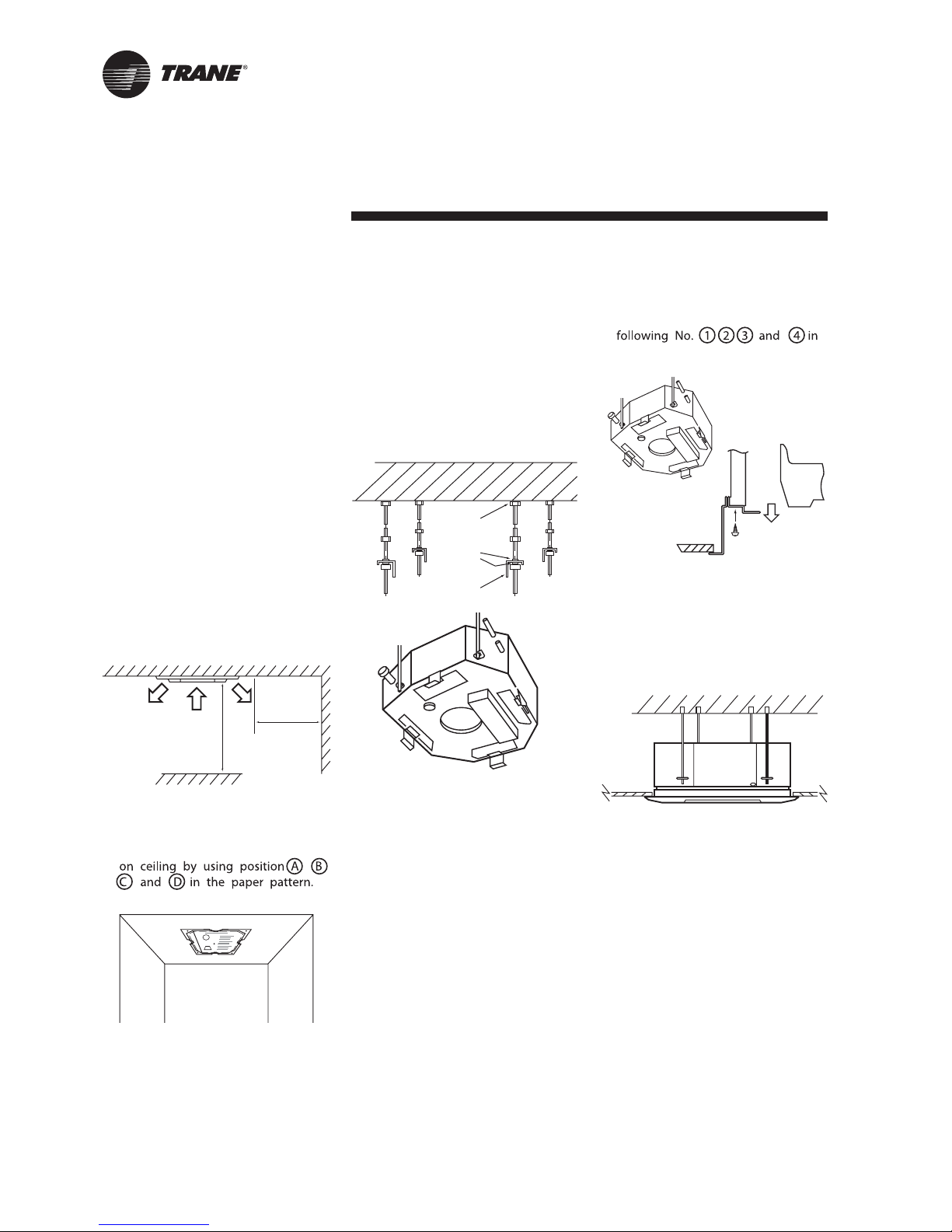
Indoor Unit Installation
• Select the location where a space
is more than 100 cm. as shown in
gure 1 also ensure that the
position dose not interfere with
light tting, sprinkle head, etc.
• Determine the ceiling hole by using
the paper pattern.
- Determine the mounting position
• Hang the four mounting rods to the
positions marked as picture shown
in gure 3 (using twelve nuts and
eight washers to support the
suspension brackets). Suspend
the unit to the mounting rods.
Lock the nuts, ensure for good
drainage, and check whether the
unit is on horizontal level by using
leveling guage.
• Install the leveling metal plate to
adjust the gap between the unit
and a ceiling, xing the screws
paper pattern.
• Remove four screws (M8). Fix the
front panel with the units by tighten
up four screws (M8).
Caution: Over tightening the screws
will distort the front panel.
MCC-SVN02A-EN
5
Figur e 6
Figur e 7
more than 10 cm.
more than 10 cm.
more than 10 cm.
more than 70 cm.
more than 35 cm.
more than 30 cm.
more than 10 cm.
more than 30 cm.
more than 120 cm.
more than 35 cm.
Wir eless Remote Control
Figur e 8
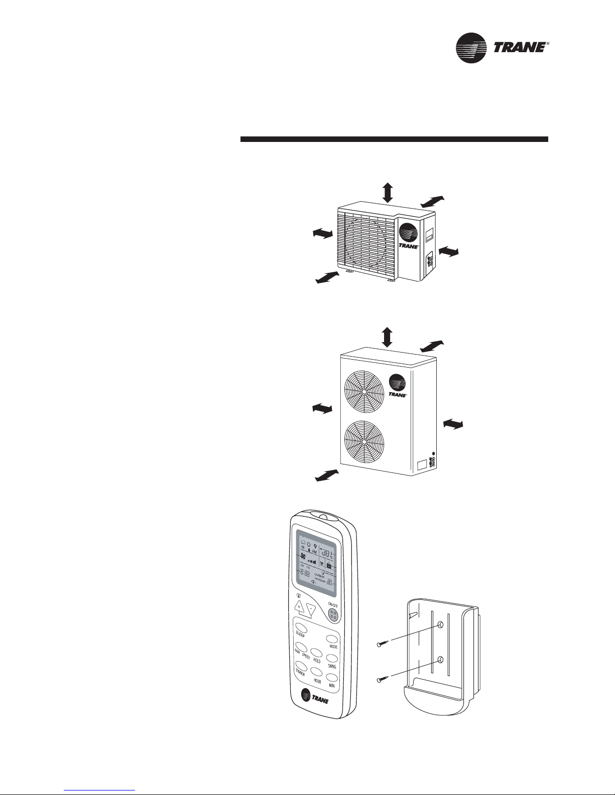
Outdoor Unit Installation
Wher e to install Outdoor
Unit
• The foundation must be solid
enough to bear the weight and
vibration of the unit.
• The space ar ound the unit is
adequate for ventilation.
• The location is not close to any
amable gases.
• The location is sufciently isolated
so that the running noise and the
hot exhaust air do not disturb the
users or their neighbors.
• Easy access to check and to
maintain.
• Ensur e the spaces indicated by
arrows fr om the wall, ceiling, fence,
or other obstacles.
Caution
Installation in the following places may
cause pr oblems. If it is unavoidable to
use such places, consult with your
distributor or dealer .
• A place with machine oil.
• A saline place such as a place very
close to a seashore.
• A place with sulphur gas.
• A place where high-fr equency
waves are generated by radio
equipment, welder and medical
equipment.
Remote Contr ol
Installation
Locate and attach the wireless
remote contr ol as follows:
• Do not place the remote control
near heat sources or expose to
the direct rays of the sun.
• Do not expose the remote control
to the indoor unit’s supply air
stream.
• Do not place in a conned space.
• Attach the remote control holder
as shown in gure 8.

6
MCC-SVN02A-EN
Figure 15
Figure 10
Figure 9
Figure 11
Figure 12
Figure 13
Copper
tubing
Reamer
Before
After
Flare nut
Flare tool
Copper
tubing
Apply refrigerant
lubricant here
Flare nut
Union
epols a eviG
Figure 14
Drain hose
Connection of Refrigerant Tubing
and Condensate Drain Piping
Deburring
Connecting the unit with aring
procedure
1. Flaring (If piping is procured or cut
at the site). Cut the copper tube to
the required length with a tube
cutter. It is recommended to cut
approx. 30-50 cm. longer than the
tubing length you estimate.
2. Hold each pipe downward when
cutting and remove burrs at the
end of the copper tube with a tube
reamer or le. This process is
important and should be done
carefully to make a good are
(Figure 9 and Figure 10).
A good are should have the
following characteristics:
- Inside surface is glossy and
smooth.
- Edge is smooth.
- Tapered sides are of uniform length.
Bending
5. When bending the tube, be careful
not to crush it. To prevent crushing
of the tube, bend it gently and do
not bend the tube at a radius
curvature of less than 100 mm.
6. If the copper tube is bent or pulled
too often, it will become sti. Do
not bend the pipe more than three
times at one place.
Cautions before Connecting
Tubes Tightly
7. Be sure to apply a sealing cap
or water-proof tape to prevent
dust or water from getting into
the tubes before they are used.
8. Be sure to apply refrigerant
lubricant to the matching surfaces
of the are and union before
connecting them together. This
is eective for reducing gas leaks
(Figure 12).
10. Tighten the are nut to the
specied tightening torque with
torque wrench and adjustable
wrench.
Condensate Drain Piping
- The drain hose should run straight
down the wall to a level where the
runo will not stain the wall.
- There should be no traps. Avoid
putting the end of the hose in
water.
- To conveniently drain the system,
the drain hose must slant
downward, with a slope of at least
1 : 50 to prevent leakage as shown
in gure 14.
When reaming, hold the tube end
downward and be sure that no
copper scraps fall into the tube.
3. Remove the are nut from the
unit and be sure to mount it on
the copper tube.
4. Make a are at the end of copper
tube with a are tool (Figure 11).
Connection
9. For proper connection, align the
union tube and are tube straight
with each other, then screw in the
are nut lightly at rst to obtain a
smooth match (Figure 13).
- When the drain hose is placed in
the room, insulate the hose with
foam polyethylene to avoid
damage to the ceiling or furniture.
- After completing installation of
refrigerant lines, wiring and drain
connections, bind the tubing,
wiring and drain hose (check if
local codes permit binding) into a
bundle by using tape at 100 or
200 mm (4" to 8") intervals. Make
sure the drain hose is at the bottom
of the bundle (Figure 15).

MCC-SVN02A-EN
7
Leak Check and System Evacuation
Leak Check
After the connection operation of
refrigerant lines to both the outdoor
and indoor unit is completed, the eld
brazed connections must be checked
for leaks. Pressurize the system
through the service valve with dry
nitrogen to 250 psi. Use soap
bubbles or other leak-checking
methods to ensure that all eld joints
are leak free. If not, release pressure,
repair and repeat leak test.
System Evacuation
1. After completion of leak check,
evacuate the system.
2. Attach appropriate hoses from
manifold gauge to gas and liquid
line pressure taps.
Note: Unnecessary switching of
hoses can be avoided and
complete evacuation of all lines
leading to sealed system can be
accomplished with manifold
center hose and connecting
branch hose to a cylinder of
R-22 and vacuum pump.
3. Attach center hose of manifold
gauges to vacuum pump.
4. Evacuate the system to hold a
350 micron vacuum.
5. Close o valve to vacuum pump
and observe the micron gauge.
If gauge pressure rised above
500 microns in one (1) minute,
then evacuation is incomplete or
the system has a leak.
6. If vacuum gauge does not rise
above 500 microns in one (1)
minute, the evacuation should
be complete.
7. With vacuum pump and micron
gauge blanked o, open valve on
R-22 cylinder and allow refrigerant
pressure to build up to about 40
psig.
8. Close valve on the R-22 supply
cylinder. Close valves on manifold
gauge set and remove refrigerant
charging hoses from liquid and
gas gauge ports.
9. Leak test the entire system. Using
proper procedures and caution,
repair any leaks found and repeat
the leak test.
Refrigerant Charging Procedure
Charge refrigerant through the gauge
port on the liquid line until pressure at
gauge is up to 120-150 psi. Once the
charge enters the system, backseat
(open) the liquid line service valve and
disconnect the charging line and
replace the cap on the gauge port.
Gaseous Charging
This procedure is accomplished
with the unit operating. Electrical
connections must be complete.
Do not proceed until the system is
ready to operate.
Procedure
1. Connect R-22 drum with gauge
manifold to the Schrader valves
(pressure taps) on the compressor
discharge and suction lines.
2. Turn on power to the unit. Allow
the system to run for ve to ten
minutes to stabilize operating
conditions.
3. Once proper airow is established,
observe the suction and head
pressure gauges on the gauge
manifold. Pressure reading should
fall approximately at the normal
points. Add or remove refrigerant
(gas only) as required to obtain
correct head and suction pressures.
Check suction line superheat and
condenser sub-cooling to ensure
the unit is operating properly.
4. Disconnect all power to the unit.
5. Remove the charging system from
the unit and close the opening in
the bottom of the control box with
the pivotal cover before attempting
to replace access panel.
Liquid pressure
Suction pressure
Vacuum pump
R-22
Service hose
Liquid line
Suction
line
Electrical connection
Figure 16


MCC-SVN02A-EN
9
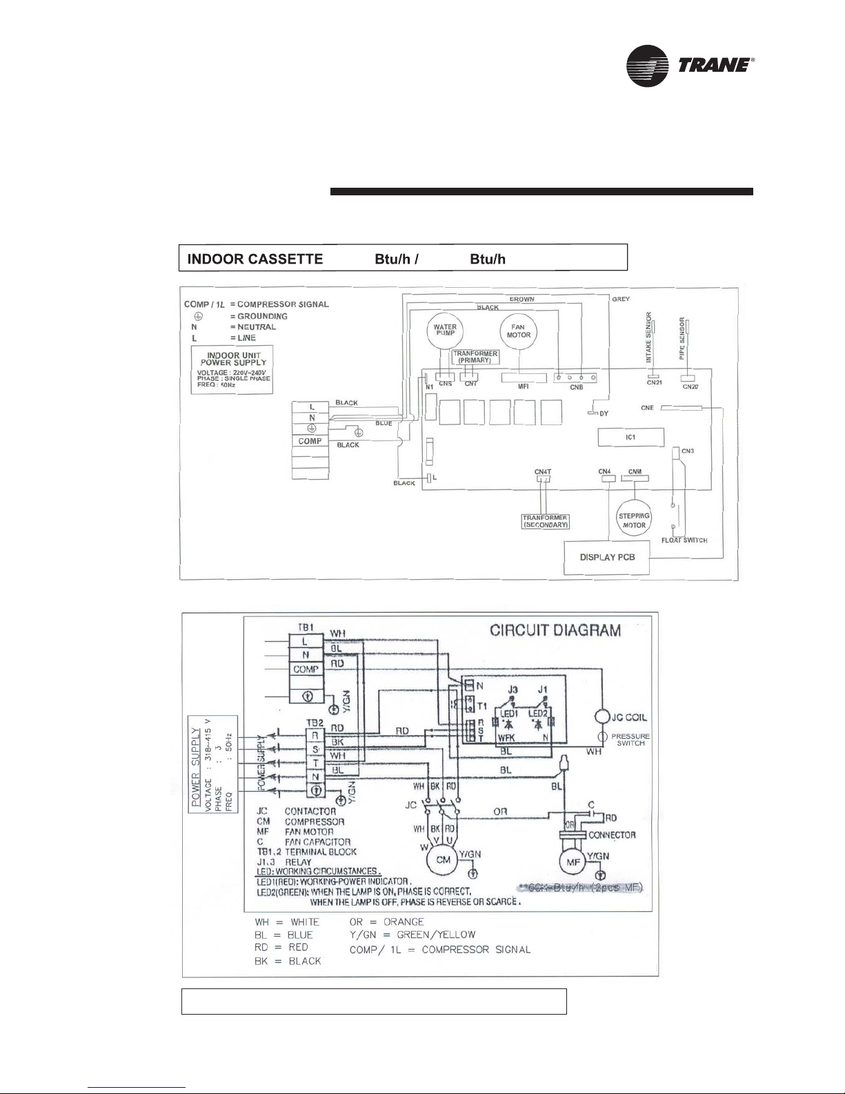
Wiring Diagram
OUTDOOR CASSETTE 18000 Btu/h & 24000 Btu/h
220-240/1/50 Hz
380-420/3/50 Hz
MCC518-048ZB

MCC-SVN02A-EN
10
Wiring Diagram
OUTDOOR CASSETTE 30000 Btu/h
MCC-SVN02A-EN
11
Wiring Diagram
OUTDOOR CASSETTE 36,000 Btu/h & 48,000 Btu/h
36,000 48,000

12
MCC-SVN02A-EN
MCC518ZB MCC524ZB MCC530ZB MCC536ZB MCC048ZB
A. Height above ceiling
B. Height above suspension brackets
C. Height of condensate drain above ceiling
D. Pipe exit position
Model
950
390
340
512
330
370
350
CEILING HOLES 860-890
418
785
drainpipe outlet
850
60
main cable entry
B
C
D
22
refrigerant pipe
Dimensional Data
A
230 230 230 290 290
100 100 100 150 150
200 200 200 200 200
150 150 150 150 150

MCC-SVN02A-EN
13
Notes

Trane has a policy of continuous product and product data implement and reserves the
right to change design and specications without notice.
New
 Loading...