

Page 1
Installation, Operation,
and Maintenance
Packaged Climate Changer
Air Handler
Model LPC
“FO” and later design sequence
1,500 to 15,000 cfm
July 2006
LPC-SVX01C-EN
Page 2
general
information
About This Manual
Literature Change History
Use this manual for Packaged Climate
Changer air handlers, model LPC. This is
the first revision of this manual. It
provides specific installation, operation,
and maintenance instructions for “DO”
and later design sequences. For
previous design sequence information,
contact your local Trane representative.
Warnings and Cautions
Warnings and cautions appear at
appropriate sections throughout this
manual. Read these carefully.
WARNING
Indicates a potentially hazardous
situation, which could result in death
or serious injury if not avoided.
CAUTION
Indicates a potentially hazardous
situation, which may result in minor
or moderate injury if not avoided.
Also, it may alert against unsafe
practices.
CAUTION
Indicates a situation that may result
in equipment or property-damageonly accidents.
Sample Warnings and Cautions
WARNING
Hazardous Voltage w/Capacitors!
Disconnect all electric power,
including remote disconnects and
discharge all motor start/run
capacitors before servicing. Follow
proper lockout/tagout procedures to
ensure the power cannot be
inadvertently energized. Verify with
an appropriate voltmeter that all
capacitors have discharged. Failure to
disconnect power and discharge
capacitors before servicing could
result in death or serious injury.
CAUTION
Use Copper Conductors Only!
Unit terminals are not designed to
accept other types of conductors.
Failure to use copper conductors may
result in equipment damage.
Special Note on Refrigeration
Emissions
World environmental scientists have
concluded that ozone in our upper
atmosphere is being reduced due to the
release of CFC fully halogenated
compounds.
Trane urges all HVAC service personnel
to make every effort to prevent any
refrigerant emissions while installing,
operating, or servicing equipment.
Always conserve refrigerants for
continued use.
Additional specific information on
refrigerant handling is included in this
manual where applicable.
Common HVAC Acronyms
For convenience, a number of acronyms
and abbreviations are used throughout
this manual. These acronyms are
alphabetically listed and defined below.
BAS = Building automation systems
cfm = Cubic-feet-per-minute
ewt = entering water temperature
F/A = Fresh air
HVAC = Heating, ventilation and air
conditioning
I/O = Inputs/outputs
IOM= Installation, operation, and
maintenace manual
LH = Left-hand
O/A = Outside air
R/A = Return air
RH = Right-hand
rpm = Revolutions-per-minute
S/A = Supply air
w.c. = Water column
ZSM = Zone sensor module
© 2006 American Standard All rights reserved LPC-SVX01C-EN
Page 3

contents
Cross reference to related publications/information for model LPC units with Tracer
AH540 controls:
• Installation, Operation, and Programming Guide for Tracer AH540 Unit Controller,
CNT-SVX05B-EN
• Packaged Climate Changer Air Handler Catalog, CLCH-PRC007-EN
Installation ……………………………………………………………2
general information ……………………………………………2
dimensions & weights ………………………………………14
pre-installation considerations ………………………………27
mechanical requirements …………………………………29
electrical requirements ………………………………………33
installation procedure ………………………………………36
pre-startup requirements ……………………………………40
Operation ……………………………………………………………43
general information …………………………………………43
sequence of operation ………………………………………59
Maintenance…………………………………………………………86
diagnostics ……………………………………………………86
troubleshooting ………………………………………………89
maintenance procedures ……………………………………96
appendix ………………………………………………………99
LPC-SVX01C-EN 3
Page 4

general
information
General
Packaged Climate Changer units are
draw-through air handlers that are
designed for cooling and/or heating
conditions of 1,500 to 15,000 nominal cfm.
Basic unit components consist of coil(s),
condensate drain pan, filter, one fan
wheel, motor and drive.
Unit control options range from the
simple control interface for field-mounted
controllers to the sophisticated Tracer
AH540. For more information on the
Tracer AH540 controls, see the Operation
section of this manual.
Refrigerant Handling
Procedures
Environmental Accountability Policy
Trane urges that all HVAC servicers to
make every effort to eliminate, if possible,
or vigorously reduce the emission of CFC,
HCFC, and HFC refrigerants to the
atmosphere. Always act in a responsible
manner to conserve refrigerants for
continued usage even when acceptable
alternatives are available.
Recover and Recycle Refrigerants
Never release refrigerant to the
atmosphere! Always recover and/or
recycle refrigerant for reuse,
reprocessing (reclaimed), or properly
dispose if removing from equipment.
Always determine the recycle or reclaim
requirements of the refrigerant before
beginning the recovery procedure. Obtain
a chemical analysis of the refrigerant if
necessary. Questions about recovered
refrigerant and acceptable refrigerant
quality standards are addressed in ARI
Standard 700.
Refrigerant Handling and Safety
Consult the manufacturer’s material
safety data sheet (MSDS) for information
on refrigerant handling to fully
understand health, safety, storage,
handling, and disposal requirements. Use
the approved containment vessels and
refer to appropriate safety standards.
Comply with all applicable transportation
standards when shipping refrigerant
containers.
Service Equipment and Procedures
To minimize refrigerant emissions while
recovering refrigerant, use the
manufacturer’s recommended recycling
equipment per the MSDS. Use
equipment and methods which will pull
the lowest possible system vacuum while
recovering and condensing refrigerant.
Equipment capable of pulling a vacuum of
less than 1,000 microns of mercury is
recommended.
Do not open the unit to the atmosphere
for service work until refrigerant is fully
removed/recovered. When leak-testing
with trace refrigerant and nitrogen, use
HCFC-22 (R-22) rather than CFC-12 (R-
12) or any other fully-halogenated
refrigerant . Be aware of any new leak
test methods which may eliminate
refrigerants as a trace gas. Perform
evacuation prior to charging with a
vacuum pump capable of pulling a
vacuum of 1,000 microns of mercury or
less. Let the unit stand for 12 hours and
with the vacuum not rising above 2,500
microns of mercury.
A rise above 2,500 microns of mercury
indicates a leak test is required to locate
and repair any leaks. A leak test is
required on any repaired area.
Charge refrigerant into the equipment
only after equipment does not leak or
contain moisture. Reference proper
refrigerant charge requirements in the
maintenance section of this manual to
ensure efficient machine operation. When
charging is complete, purge or drain
charging lines into an approved refrigerant container. Seal all used refrigerant
containers with approved closure devices
to prevent unused refrigerant from
escaping to the atmosphere. Take extra
care to properly maintain all service
equipment directly supporting refrigerant
service work such as gauges, hoses,
vacuum pumps, and recycling equipment
.
When cleaning system components or
parts, avoid using CFC-11 (R-11) or CFC113 (R-113). Use only cleaning-solvents
that do not have ozone depletion factors.
Properly dispose of used materials.
Refrigeration system cleanup methods
using filters and driers are preferred.
Check for leaks when excessive purge
operation is observed.
Keep abreast of unit enhancements,
conversion refrigerants, compatible
parts, and manufacturer’s recommendations that will reduce refrigerant emissions and increase equipment operating
efficiencies.
4 LPC-SVX01C-EN
Page 5
general
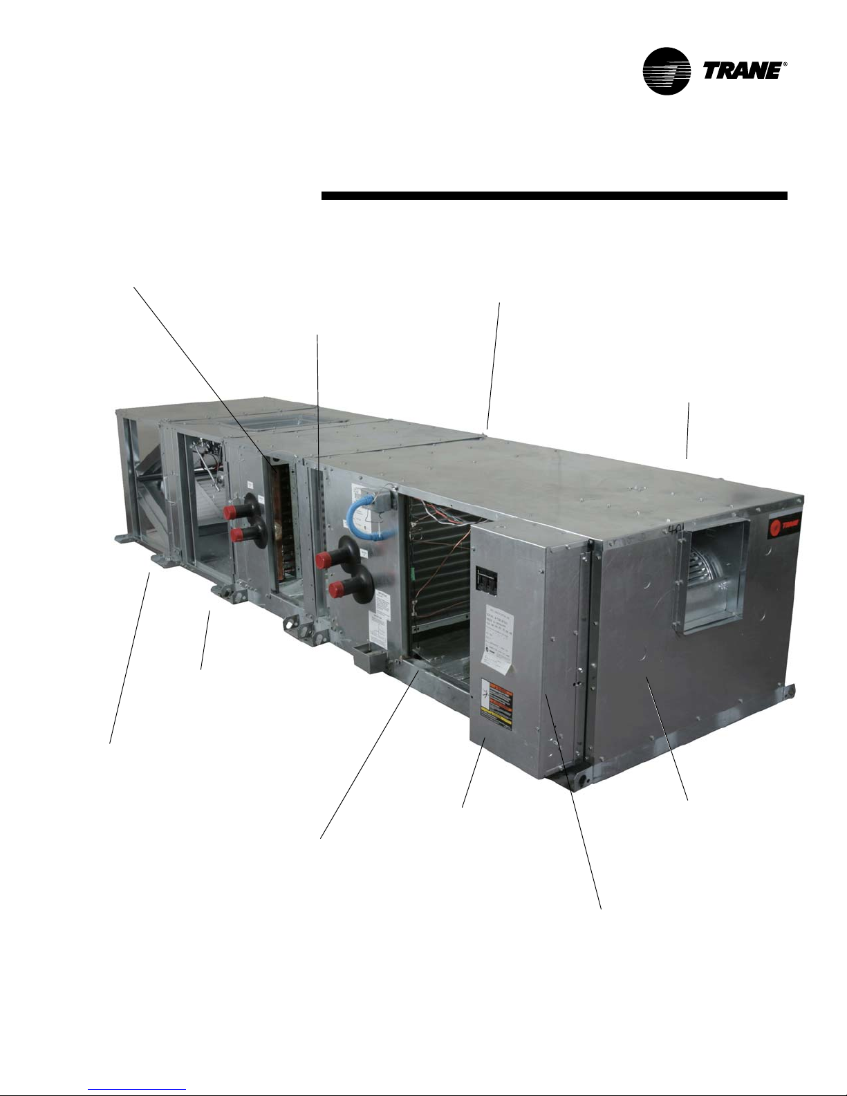
Access section option
• with or without preheat coil
• one or two-row hot water
(9, 12, or 14 fpi) or
• one-row steam distributing
coil (6 fpi)
Installation
Internal filter frame
accommodates
two-inch filters
information
Galvanized steel cabinet
• matt-faced insulation
• foil face insulation optional
• double wall insulation optional
• 2-inch flat filter option on main
section
Sizes: 03, 06, 09, 10, 12, 14, 17, 21, 25
or 30 square feet
• 1,500 to 15,000 cfm (708 to 4956 l/s)
• UL/CUL listing
• ARI 410 and 430 listed
• Meets ARI 260 acoustic ratings
Face & bypass option
helps control preheat
Filter section option
• 2-inch, MERV 7, angle filters
• 4-inch, MERV 7, flat filters
• 4-inch, MERV 12, flat filters
Other options include:
• electric heat with single-point
power connections, reheat
position
• factory mounted and wired
disconnect with motor
overloads
• variable frequency drive factory
mounted and wired
Figure I-GI-1. Packaged Climate Changer air handler unit components. Horizontal unit is shown.
LPC-SVX01C-EN 5
Up to 8 rows of coil
• 4 or 6 row DX coil with 9,
12, or 14 fpi
• 4, 6, or 8-row chilled water
with 9, 12, or 14 fpi
• 1 or 2-row hot water coil,
reheat or preheat with 9,
12, or 14 fpi
• 1-row steam coil, 6 fpi,
reheat or preheat
Belt-driven motor
• Internal spring isolation
optional
1
/2 to 20 hp
•
• 650 to 1900 rpm
Forward-curved fan
• fixed pitch or variable
pitch sheaves
• constant volume or
variable air volume
Control options
• control interface
• Tracer AH540
DDC controller
Page 6

general
Installation
Ultraviolet (UV) Germicidal
Irradiation Lights
The United States Environmental
Protection Agency (EPA) believes that
molds and bacteria inside buildings have
the potential to cause health problems in
sensitive individuals
Trane provides ultraviolet lights (UV-C) as
a factory-engineered and installed option
in select commercial air handling
products for the purpose of reducing
microbiological growth (mold and
bacteria) within the equipment. When
factory provided, polymer materials that
are susceptible to deterioration by the
UV-C light will be substituted or shielded
from direct exposure to the light. In
addition, UV-C radiation can damage
human tissue, namely eyes and skin. To
reduce the potential for inadvertent
exposure to the lights by operating and
maintenance personnel, electrical
interlocks that automatically disconnect
power to the lights are provided at all unit
entry points to equipment where lights
are located
Note:
1. United States Environmental Protection Agency;
Moisture and your Home;
402-K-02-003. It’s available online, at
www.epa.gov. Enter “guide to mold” in
the search box to view.
A Brief Guide to Mold,
(Note 1). If specified,
Brochure EPA
information
WARNING
Equipment Damage From
Ultraviolet (UV) Lights!
Trane does not recommend field
installation of ultraviolet lights in
its air handling equipment for the
intended purpose of improving
indoor air quality. High intensity
C-band ultraviolet light is known
to severely damage polymer
(plastic) materials and poses a
personal safety risk to anyone
exposed to the light without
proper personal protective
equipment (can cause damage to
eyes and skin). Polymer materials
commonly found in HVAC
equipment that may be
susceptible include insulation on
electrical wiring, fan belts,
thermal insulation, various
fasteners and bushings.
Degradation of these materials
can result in serious damage to
the equipment. Trane accepts no
responsibility for the performance
or operation of our air handling
equipment in which ultraviolet
devices were installed outside of
the Trane factory.
6 LPC-SVX01C-EN
Page 7
general
Installation
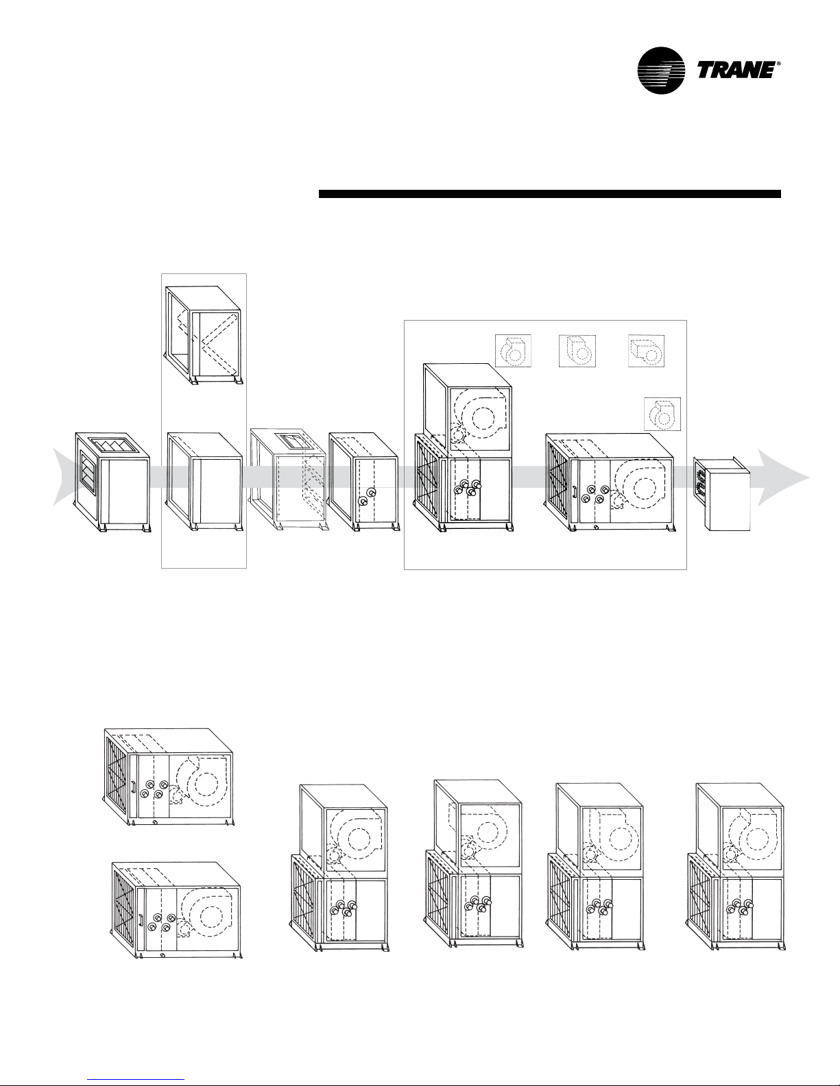
Packaged Climate Changer Unit Configurations and Optional Sections
Vertical Unit Fan Discharge Options
Top Front Top Back
Angle Filter
Section OR
OR
Mixing
Section
Flat Filter
Section
Optional Sections
Face & Bypass
Section
Coil Access
Section
Vertical Unit, Front Top
Discharge
Main Unit Section Configurations
information
Back Top
Horizontal Unit Fan
Discharge Option
Horizontal Unit, Front Top
Discharge
Top Front
Electric Heat
Section
Optional
Section
Available Fan Discharge Configurations Detail
Horizontal Unit, Top Front Fan Discharge
Horizontal Unit, Front Top Fan Discharge
LPC-SVX01C-EN 7
Vertical Unit, Front Top
Fan Discharge
Vertical Unit, Back Top
Fan Discharge
Vertical Unit, Top Back
Fan Discharge
Vertical Unit, Top Front
Fan Discharge
Page 8
general
Installation
information
Table I-GI-1. Packaged Climate Changer General Data
Unit size 3 6 8 10 12 14 17 21 25 30
Unit nominal airflow, cfm 1500 3000 4000 5000 6000 7000 8500 10500 12500 15000
Hydronic & DX coil
coil area, ft
width, in. 17.5 22.5 27.5 27.5 35.0 35.0 45.0 45.0 51.2 51.2
length, in. 23.0 36.0 39.0 51.0 51.0 59.0 54.0 66.0 68.0 81.0
velocity, ft./min. 536.7 533.3 537.1 513.3 484.0 488.1 503.7 509.1 516.5 520.3
dry weight, lbs.
1-row 23.5 35.0 41.8 51.5 66.2 72.1 82.8 93.2 109.7 122.5
2-row 29.5 46.3 56.8 70.8 91.0 100.5 116.6 134.2 168.5 190.2
4-row 46.6 75.8 94.7 120.5 152.8 170.7 207.3 240.7 276.3 317.0
6-row 58.6 98.5 124.7 159.3 202.4 227.8 274.9 322.8 372.7 431.2
8-row 73.6 125.4 159.5 204.7 259.4 292.9 351.3 414.5 479.5 556.8
wet weight, lbs.
1-row 29.2 43.6 52.5 64.0 85.8 93.2 108.2 121.5 141.9 158.2
2-row 37.7 59.0 73.0 90.5 119.9 132.4 161.1 184.4 226.6 255.4
4-row 59.8 97.6 123.1 155.7 201.6 225.4 279.1 323.9 373.1 427.8
6-row 76.9 129.4 165.2 210.0 271.2 305.3 374.0 438.9 508.2 587.7
8-row 96.9 165.5 212.2 271.0 348.2 393.3 477.6 563.5 653.7 759.0
waterflow limits
1-row
min. gpm
max. gpm
2, 4, 6, & 8-row
min. gpm
max. gpm
volume, gallons
1-row 0.7 1.0 1.3 1.5 2.3 2.5 3.1 3.4 3.9 4.3
2-row 1.0 1.5 2.0 2.4 3.5 3.8 5.3 6.0 7.0 7.8
4-row 1.6 2.6 3.4 4.2 5.9 6.6 8.6 10.0 11.6 13.3
6-row 2.2 3.7 4.9 6.1 8.3 9.3 11.9 13.9 16.3 18.8
8-row 2.8 4.8 6.3 7.9 10.6 12.0 15.2 17.9 20.9 24.3
Steam coil
area, ft
width, in.
length, in.
area, ft
width, in.
length, in.
weight, lbs. 31.7 54.8 74.8 86.0 114.1 123.3 157.6 179.9 200.0 224.2
Fan/motor data
fan wheel size, in. 9x7 12x9 12x12 15x15 18x15 18x18 20x15 20x20 20x18 22x20
max rpm 2000 1500 1700 1400 1200 1200 110 0 1000 1300 1150
motor HP
min. design cfm
max. design cfm
2 and 4-in. Flat filter data
quantity - size in. 1 - 20x25 2 - 20x25 2 - 20x25 1 - 16x25 2 - 16x20 2 - 16x20 2 - 16x20 2 - 16x20 2 - 16x25 6 - 16x25
area, ft
nominal air velocity, ft./min. 432.0 432.0 576.0 514.3 369.2 430.8 377.8 466.7 473.5 490.2
2-in. Angle filter section data
quantity - size in. 2 - 16x25 4 - 20x20 4 - 20x20 4 - 20x20 9 - 20x20 9 - 20x20 6 - 16x25 6 - 16x25 4 - 16x20 12 - 16x20
area, ft
velocity, ft./min. 270.0 270.0 360.0 321.3 240.0 280.0 226.7 280.0 296.2 306.7
Mixing section
nominal air velocity, ft./min. 966.4 1066.3 1123.4 1120.4 1184.1 1161.7 1171.1 1120.1 1218.5 1247.1
2
2 Note 7
2
2
2
Note 5
Note 6
Notes 5 & 7
Notes 6 & 7
Note 10
Note 10
Note 3
Note 4
Note 3
Note 4
Note 8
Note 9
2.8 5.6 7.5 9.7 12.4 14.3 16.9 20.6 24.2 28.8
6.1 7.9 9.6 9.6 12.2 12.2 15.7 15.7 17.5 17.5
32.6 42.0 51.3 51.3 65.3 65.3 83.9 83.9 93.3 93.6
6.1 14.9 18.4 18.4 23.6 23.6 30.6 30.6 35.0 35.0
32.6 79.3 51.3 51.3 65.3 125.9 163.2 163.2 186.6 186.6
1.9 4.5 6.5 8.5 11.7 13.5 6.8 8.4 11.0 13.2
12.0 18.0 24.0 24.0 33.0 33.0 18.0 18.0 24.0 24.0
23.0 36.0 39.0 51.0 51.0 59.0 54.0 67.0 66.0 79.0
– – – – – – 9.0 11.2 11.0 13.2
– – – – – – 24.0 24.0 24.0 24.0
– – – – – – 54.0 67.0 66.0 79.0
1
/2 - 2
1050 2100 2800 3500 4200 4900 5950 7350 8750 10500
1
/2 - 3
3
/4 - 5 1 - 5 1 - 7 1/
1 - 7 1/
2
1 -10 2 - 15 3 - 20 3 - 20
2
1800 3600 4800 6000 7200 8400 10200 12600 15000 18000
2 - 20x25 1 - 16x25 1 - 16x25 2 - 16x25 2 - 16x25 6 - 20x25 4 - 20x25
2 - 20x20 2 - 20x20 2 - 20x20 2 - 20x20
1 - 20x25 1 - 20x25 2 - 20x25 2 - 20x25
3.5 6.9 6.9 9.7 16.3 16.3 22.5 22.5 26.4 30.6
2 - 16x20 6 - 20x25 6 - 20x25 12 - 20x20 8 - 20x20
5.6 11.1 11.1 15.6 25.0 25.0 37.5 37.5 42.2 48.9
Notes: 1. Coil width = length in the direction of a coil header, typically vertical. 2. Coil length = length of coil in direction of the coil tubes, typically horizontal and perpendicular to airflow.
3. Unit sizes 17-30 have two stacked steam coils. 4. To prevent erosion/noise problems. 5. Coil width = length in the direction of a coil header, typically vertical. 6 . Coil length = length of
coil in direction of the coil tubes, typically horizontal and perpendicular to airflow. 7. The minimum waterflow is to assure self venting of the coil. There is no minimum water flow limit
for coils that do not require self venting. 8. Minimum airflow limit is for units with hot water, steam, or electric heat. There is no minimum airflow for cooling only units. 9. Due to
moisture carryover limits. 10. Coil weight based on 12 fpi coil.
8 LPC-SVX01C-EN
Page 9
general
Installation
information
Table I-GI-2. Available motor horsepower and unit voltage
unit voltage
1
/
2
3
/
4
11
1
/
2
208/60/1 zzz
230/60/1 zzz
277/60/1 zzz
208/60/3 z zzzz z zzz zz
230/60/3 z zzzz z zzz zz
460/60/3 z zzzz z zzz zz
575/60/3 zzz z zzz zz
380/50/3 zzz z zzz z
415/50/3 zzz z zzz z
motor horsepower
2357
1
/
2
10 15 20
Table I-GI-3. Available motor horsepower by unit size
unit size
1
/
2
3
/
4
11
1
/
2
3 z zzzz
6 z zzzz z
8 zzzz z z
10 zzzzz
12 zzzzzz
14 zzzzzz
17 zzz z zzz
21 z z zzz
25 z zzz zz
30 z zzz zz
motor horsepower
2357
1
/
2
10 15 20
LPC-SVX01C-EN 9
Page 10
general
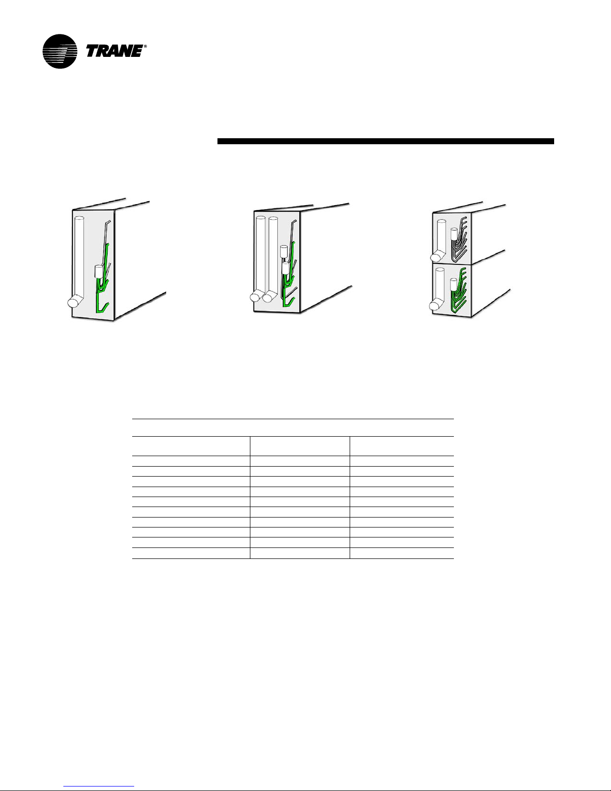
Dx Coil Options
Figure I-GI-1. Single Circuit DX Coil
Installation
Figure I-GI-2. Intertwined DX Coil
information
Figure I-GI-3. Horizontal Face Split DX Coil
Table I-GI-5. Packaged Climate Changer DX Coil Configuration Options
Coil
Configuration Single Horizontal Face Split Intertwined
Unit # # Coil Fin # # Coil Fin # # Coil Fin
Size Dist. Circuits Width Length Dist. Circuits Width Length Dist. Circuits Width Length
3 1 3 17.5 23.0 – – – – – – – –
6 1 5 22.5 36.0 – – – – – – – –
8 1 7 27.5 39.0 2 7 27.5 39.0 2 7 27.5 39.0
10 1 10 27.5 51.0 2 10 27.5 51.0 2 10 27.5 51.0
12 – – – – 2 13 35.0 51.0 2 13 35.0 51.0
14 – – – – 2 13 35.0 59.0 2 13 35.0 59.0
17 – – – – 2 17 45.0 54.0 4 17 45.0 54.0
21 – – – – 2 17 45.0 66.0 4 17 45.0 66.0
25 – – – – 2 20 51.3 68.0 4 20 51.5 68.0
30 – – – – 4 40 51.3 81.0 4 40 51.3 81.0
Note: 4-row coils have a 3/16" distributor. 6-row coils have a 1/4" distributor.
10 LPC-SVX01C-EN
Page 11

general
Installation
information
Packaged Climate Changer Model Number Description
Following is a complete description of the Packaged Climate Changer model number. Each digit in the model number has a
corresponding code that identifies specific unit options.
LPC A A 08 F 2 F0 L L B 0 0 000 0 0 A F B H B 0 0 0 0 0 0 0 0 0 0 0
1,2,3 4 5 6,7 8 9 10,11 12 13 14 15 16 17,18,19 20 21 22 23 24 25 26 27 28 29 30 31 32 33 34 35 36 37
Digit 1, 2, 3 - Unit model
LPC = Packaged Climate Changer
Digit 4 - Development sequence
A = “A” development sequence
Digit 5 - Configuration
A = horizontal/front top
B = horizontal/top front
C = vertical/front top
D = vertical/top front
E = vertical/back top
F = vertical/top back
Digit 6, 7 - Unit size
03 = 3 square feet of coil
06 = 6 square feet of coil
08 = 8 square feet of coil
10 = 10 square feet of coil
12 = 12 square feet of coil
14 = 14 square feet of coil
17 = 17 square feet of coil
21 = 21 square feet of coil
25 = 25 square feet of coil
30 = 30 square feet of coil
Digit 8 - Unit voltage
0 = no motor, controls, electric heat
A = 208/60/1
B = 230/60/1
C = 277/60/1
D = 208/60/3
E = 230/60 /3
F = 460/60/3
G = 575/60/3
H = 380/50/3
J = 415/50/3
Digit 9 - Insulation & Isolation
1 = 1 inch, m att faced
2 = 1 in ch, foil faced
3 = 1 inch, double-wall with field provided
external isolaiton
4 = 1 inch, double-wall with internal
isolation
Digit 10,11 - Design sequence
Digit 12 - Drain pan type, coil & motor
connection location
R = polymer drain pan, RH coil & motor
L = polymer drain pan, LH coil & motor
C = polymer drain pan, RH coil & LH motor
D = polymer drain pan, LH coil & RH motor
E = SS drain pan, RH coil & motor
F = SS drain pan, LH coil & motor
G = SS drain pan, RH coil & LH motor
H = SS drain pan, LH coil & RH motor
LPC-SVX01C-EN 11
Digit 13 - Unit Coil #1 Type (1st in Air Stream)
0 = no unit coil #1
hydronic heat coils
A = 1-row, 9 fpi
B = 1-row, 12 fpi
C = 1-row, 14 fpi
D = 2-row, 9 fpi
E = 2-row, 12 fpi
F = 2-row, 14 fpi
chilled hydronic coils
G = 4-row, 9 fpi
H = 4-row,12 fpi
J = 4-row, 14 fpi
K = 6-row, 9 fpi
L = 6-row, 12 fpi
M = 6-row, 14 fpi
N = 8-row, 9 fpi
P = 8-row, 12 fpi
R = 8-row, 14 fpi
DX coils, 3/16” distributor
T = 4-row, 9 fpi
U = 4-row, 12 fpi
V = 4-row, 14 fpi
Steam Coil
1 = 1-row, 6 fpi
DX coils, 1/4” distributor
5 = 6-row, 9 fpi
6 = 6-row DX, 12 fpi
7 = 6-row DX, 14 fpi
Digit 14 - Unit coil #2 type (2nd in air
stream)
0 = no unit coil #1
hydronic reheat coils
A = 1-row, 9 fpi
B = 1-row, 12 fpi
C = 1-row, 14 fpi
D = 2-row, 9 fpi
E = 2-row, 12 fpi
F = 2-row, 14 fpi
chilled hydronic coils
G = 4-row, 9 fpi
H = 4-row,12 fpi
J = 4-row, 14 fpi
K = 6-row, 9 fpi
L = 6-row, 12 fpi
M = 6-row, 14 fpi
DX coils, 3/16” distributor
N = 4-row, 9 fpi
P = 4-row, 12 fpi
R = 4-row, 14 fpi
steam coil
W = 1-row, 6 fpi
DX coils, 1/4” distributor
2 = 6-row, 9 fpi
3 = 6-row, 12 fpi
4 = 6-row, 14 fpi
Digit 15 - Access section (preheat)
0 = none
hydronic coils
A = 1-row, 9 fpi
B = 1-row, 12 fpi
C = 1-row, 14 fpi
D = 2-row, 9 fpi
E = 2-row, 12 fpi
F = 2-row, 14 fpi
G = 1-row steam coil, type NS, 6 fpi
R = no coil, matt face insulation
Digit 16 - Electric heat, factory mounted
only
0 = none
1 = electric heat with 1 stage
2 = electric heat with 2 stages
4 = electric heat with 4 stages
Digit 17, 18, 19 - Electric heater kW
006 - 018 = 1 kW increments
020 - 038 = 2 kW increments
041 - 059 = 3 kW increments
063 - 095 = 4 kW increments
95 and < = 5 kW increments
Digit 17, 18, 19 - Electric heater kW
Digit 20 - Control type
0 = none
1 = control interface
2 = Tracer AH540 zone temp. control
3 = Tracer AH540 discharge temp. control
Digit 21 = Electric heater options
0 = none
A = line fuse
B = door interlocking disconnect switch
C = air flow switch
combined options
D = A and B
E = A and C
F = B and C
G = A, B, and C
Digit 22 – Refrigerant circuit options
0 = none
1 = single circuit with one stage DX
2 = face split circuit with 2 stage DX
3 = intertwined circuit with 2 stage DX
5 = single circuit with 2 stage DX
6 = face split circuit with 4 stage DX
7 = intertwined circuit with 4 stage DX
Page 12

general
Digit 23 - Motor horsepower (hp)
0 = none
A = 1/2 hp
B = 3/4 hp
C = 1 hp
D = 1 1/2 hp
E = 2 hp
F = 3 hp
G = 5 hp
H = 7 1/2 hp
J = 10 hp
K = 15 hp
L = 20 hp
Digit 24 - Volume control
A = CV with variable pitch sheaves
B = CV with fixed pitch sheaves
C = VFD with fixed pitch sheaves
Digit 25 – Drives, fixed/variable
0 = none
A = 650 rpm/600 – 700 rpm
B = 700 rpm/650 – 750 rpm
C = 750 rpm/700 – 800 rpm
D = 800 rpm/750 – 850 rpm
E = 850 rpm/800 – 900 rpm
F = 900 rpm/850 – 950 rpm
G = 950 rpm/900 – 1000 rpm
H = 1000 rpm/950 – 1050 rpm
J = 1050 rpm/1000 – 1100 rpm
K = 1100 rpm/1050 – 1150 rpm
L = 1150 rpm/1100 – 1200 rpm
M = 1200 rpm/1150 – 1250 rpm
N = 1250 rpm/ 1200 – 1300 rpm
P = 1300 rpm/1250 – 1350 rpm
R = 1350 rpm/1300 – 1400 rpm
T = 1400 rpm/1350 – 1450 rpm
U = 1450 rpm/1400 – 1500 rpm
V = 1500 rpm/1450 – 1550 rpm
W = 1550 rpm/1500 – 1600 rpm
Y = 1600 rpm/1550 – 1650 rpm
Z = 1650 rpm/1600 – 1700 rpm
1 = 1700 rpm/1650 – 1750 rpm
2 = 1750 rpm/1700 – 1800 rpm
3 = 1800 rpm/1750 – 1850 rpm
4 = 1850 rpm/1800 – 1900 rpm
5 = 1900 rpm/1850 – 1950 rpm
6 = 1950 rpm/1900 – 2000 rpm
7 = 2000 rpm/1950 – 2050 rpm
Digit 26 - Filter type/filter/mixing section
0 = none
A = flat unit filter
B = flat unit filter & mixing section
C = angle filter section
D = flat filter section
E = angle filter section & mixing section
F = flat filter section & mixing section
Installation
Digit 27 – Face & bypass section (F & B,
preheat position)
0 = none
A = F & B w/ NC actuator
B = F & B w/ NO actuator
C = F & B w/ field-supplied NO actuator
D = F & B w/ field-supplied NC actuator
Digit 28 - Control option
0 = none
1 = dehumidification w/RH sensor
2 = dehumidification w/comm.RH
3 = 2-pipe changeover w/EWT sensor
4 = 2-pipe changeover w/comm. EWT
5 = CO2 sensor
6 = 1 & 4
Digit 29 - Control options 1, factory
mounted
0 = none
A = low limit switch
B = condensate overflow switch
C = dirty filter switch
D = fan status switch
combined options
E = A and B
F = A and C
G = A and D
H = B and C
J = B and D
K = C and D
L = A, B, and, C
M = A, B, and D
N = A, C, and D
P = B, C, and D
R = A, B, C, and D
Digit 30 - Control options 2
0 = none
A = discharge air sensor (DAS)
B = mixed air sensor (MAS)
D = NO mixing box act.
E = NC mixing box act.
combined options
F = A and B
H = A and D
J = A and E
L = B and D
M = B and E
R = A, B, and D
T = A, B, and E
1 = field mounted, NO, mixing box act.
2 = field mounted, NC, mixing box act.
3 = DAS & field sup. NO mixing box act.
4 = DAS & field sup. NC, mixing box act.
5 = MAS & field sup. NO mixing box act.
6 = MAS & field sup. NC mixing box act.
7 = DAS, MAS field sup. NO mix. box act.
8 = DAS, MAS field sup. NC mix. box act.
information
Digit 31 - Control function
0 = none
1 = mixed air ctrl.
2 = mixed air preheat ctrl.
3 = economizing with mixed air ctrl.
4 = economizing with mixed air preheat ctrl.
Digit 32 - Control options 3, factory
provided, field installed
0 = none
A = outdoor air temperature sensor
B = duct static pressure sensor
C = A & B
D = outdoor air temperature communicated
E = duct static pressure communicated
F = D & E
Digit 33 – Preheat control valve options
0 = none
A = 3/4” 2-way, NO 7.3 Cv
B = 3/4” 2-way, NC 7.3 Cv
C = 3/4” 3-way, NO 7.3 Cv
D = 3/4” 3-way, NC 7.3 Cv
E = 1” 2-way, NO 11.6 Cv
F = 1” 2-way, NC 11.6 Cv
G = 1” 3-way, NO 11.6 Cv
H = 1” 3-way, NC 11.6 Cv
J = 1 1/4” 2-way, NO 18.5 Cv
K = 1 1/4” 2-way, NC 18.5 Cv
L = 1 1/4” 3-way, NO 18.5 Cv
M = 1 1/4” 3-way, NC 18.5 Cv
N = 1 1/2” 2-way, NO 28.9 Cv
P =1 1/2” 2-way, NC 28.9 Cv
Q = 1 1/2” 3-way, NO 28.9 Cv
R =1 1/2” 3-way, NC 28.9 Cv
T = 2” 2-way, NO 46.2 Cv
U = 2” 2-way, NC 46.2 Cv
V = 2” 3-way, NO 46.2 Cv
W = 2” 3-way, NC 46.2 Cv
X = 2 1/2” 2-way, NO 54 Cv
Y = 2 1/2” 2-way, NC 54 Cv
Z = 2 1/2” 3-way, NO 54 Cv
1 = 2 1/2” 3-way, NC 54 Cv
2 = field supplied 2-way NO
3 = field supplied 2-way NC
6 = field supplied 3-way NO
7 = field supplied 3-way NC
Note: NO = Normally open & NC = Normally closed in the
valve’s de-energized state
12 LPC-SVX01C-EN
Page 13

general
Installation
Digit 34 – Cooling control valve options
0 = none
A = 3/4” 2-way, NO 7.3 Cv
B = 3/4” 2-way, NC 7.3 Cv
C = 3/4” 3-way, NO 7.3 Cv
D = 3/4” 3-way, NC 7.3 Cv
E = 1” 2-way, NO 11.6 Cv
F = 1” 2-way, NC 11.6 Cv
G = 1” 3-way, NO 11.6 Cv
H = 1” 3-way, NC 11.6 Cv
J = 1 1/4” 2-way, NO 18.5 Cv
K = 1 1/4” 2-way, NC 18.5 Cv
L = 1 1/4” 3-way, NO 18.5 Cv
M = 1 1/4” 3-way, NC 18.5 Cv
N = 1 1/2” 2-way, NO 28.9 Cv
P = 1 1/2” 2-way, NC 28.9 Cv
Q = 1 1/2” 3-way, NO 28.9 Cv
R =1 1/2” 3-way, NC 28.9 Cv
T = 2” 2-way, NO 46.2 Cv
U = 2” 2-way, NC 46.2 Cv
V = 2” 3-way, NO 46.2 Cv
W = 2” 3-way, NC 46.2 Cv
X = 2 1/2” 2-way, NO 54 Cv
Y = 2 1/2” 2-way, NC 54 Cv
Z = 2 1/2” 3-way, NO 54 Cv
1 = 2 1/2” 3-way, NC 54 Cv
2 = field supplied, 2-way NO
3 = field supplied, 2-way NC
6 = field supplied, 3-way NC
7 = field supplied, 3-way NC
Note: NO = Normally open & NC = Normally closed in the
valve’s de-energized state
information
Digit 35 – Reheat control valve options
0 = none
A = 3/4” 2-way, NO 7.3 Cv
B = 3/4” 2-way, NC 7.3 Cv
C = 3/4” 3-way, NO 7.3 Cv
D = 3/4” 3-way, NC 7.3 Cv
E = 1” 2-way, NO 11.6 Cv
F = 1” 2-way, NC 11.6 Cv
G = 1” 3-way, NO 11.6 Cv
H = 1” 3-way, NC 11.6 Cv
J = 1 1/4” 2-way, NO 18.5 Cv
K = 1 1/4” 2-way, NC 18.5 Cv
L = 1 1/4” 3-way, NO 18.5 Cv
M = 1 1/4” 3-way, NC 18.5 Cv
N = 1 1/2” 2-way, NO 28.9 Cv
P = 1 1/2” 2-way, NC 28.9 Cv
Q = 1 1/2”3-way, NO 28.9 Cv
R = 1 1/2” 3-way, NC 28.9 Cv
T = 2” 2-way, NO 46.2 Cv
U = 2” 2-way, NC 46.2 Cv
V = 2” 3-way, NO 46.2 Cv
W = 2” 3-way, NC 46.2 Cv
X = 2 1/2” 2-way, NO 54 Cv
Y = 2 1/2” 2-way, NC 54 Cv
Z = 2 1/2” 3-way, NO 54 Cv
1 = 2 1/2” 3-way, NC 54 Cv
2 = field supplied, 2-way NO
3 = field supplied, 2-way NC
6 = field supplied 3-way NO
7 = field supplied 3-way NC
Note: NO = Normally open & NC = Normally closed in the
valve’s de-energized state
Digit 36 – External exhaust fan support
0 = none
1 = configure for control
2 = configure for exhaust fan start/stop &
status support
3 = generic temperature thermistor
Digit 37 – Zone sensor options
0 = none
1 = sensor w/off, auto, Fahrenheit knob,
on/cancel and comm jack
2 = sensor w/Fahrenheit knob, on/cancel
and comm jack
4 = sensor only
5 = field supplied zone sensor
F = standalone operator display
G = 1 & F
H = 2 & F
J = 4 & F
K = 5 & F
LPC-SVX01C-EN 13
Page 14
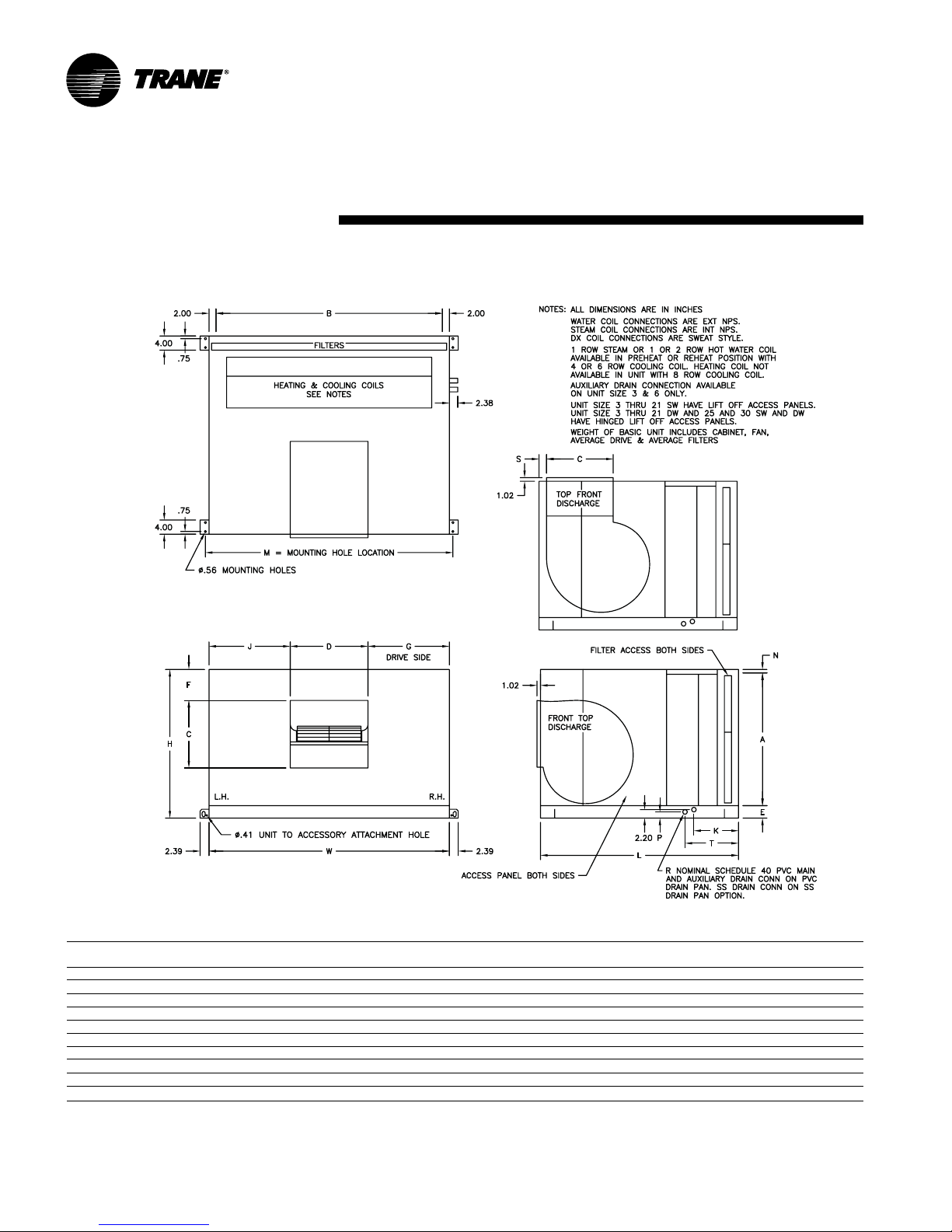
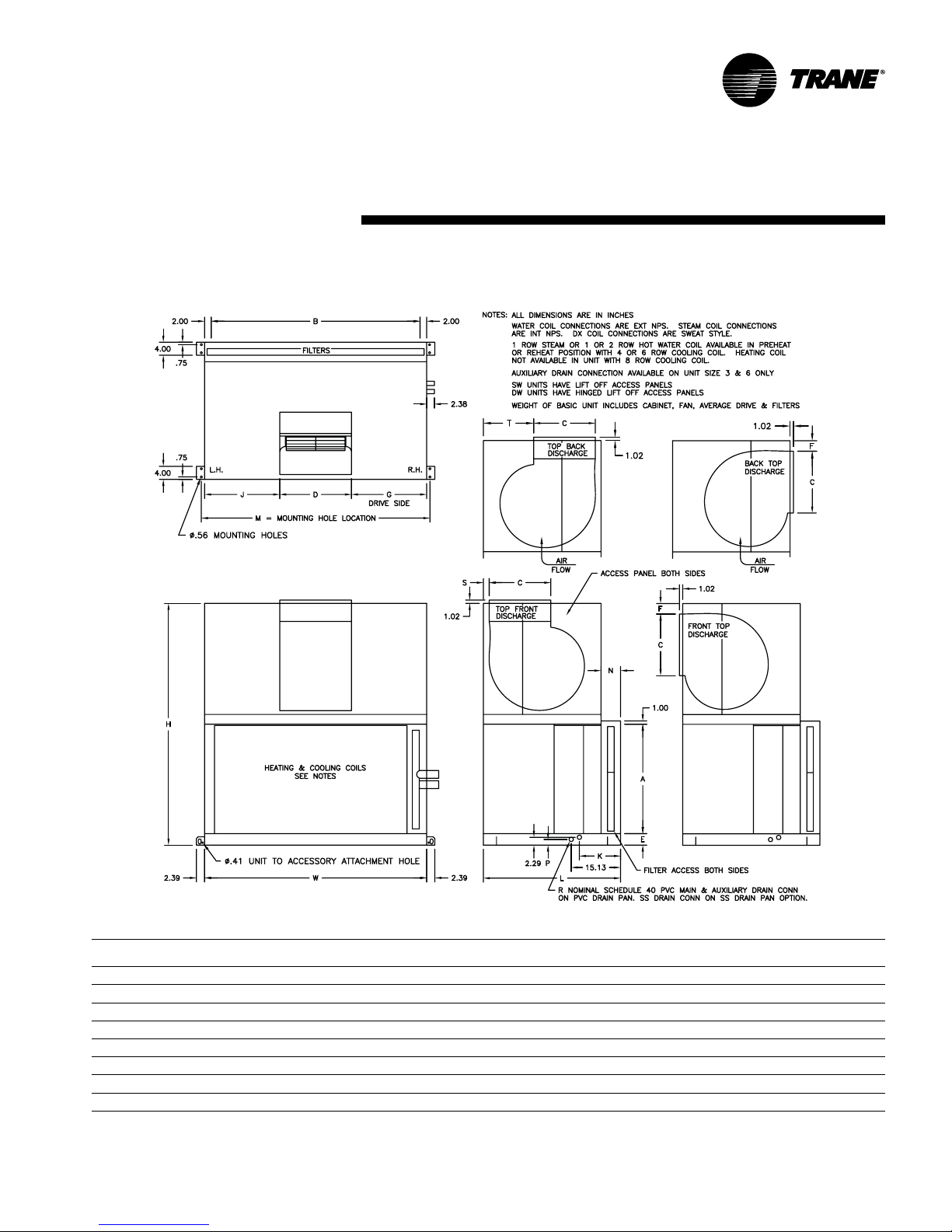
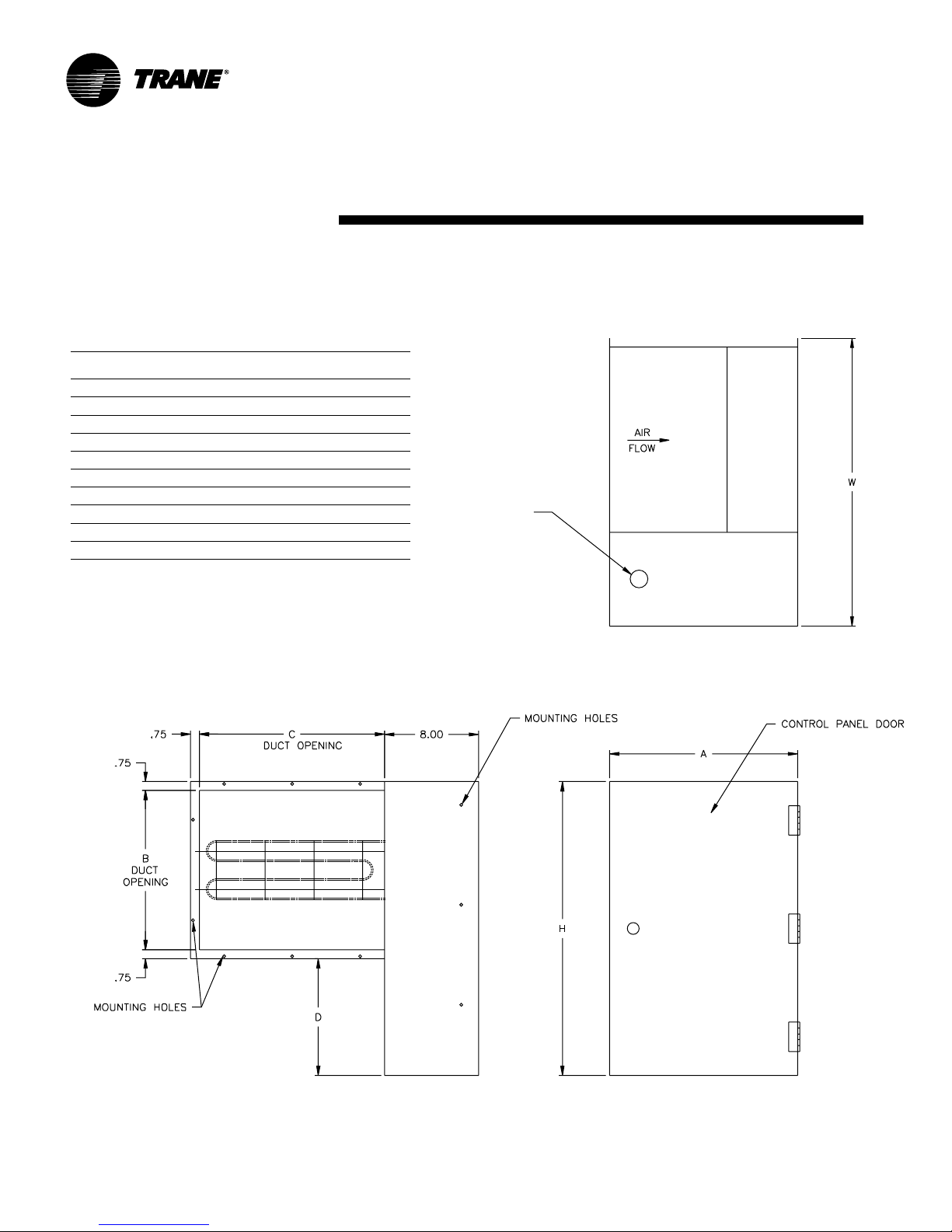
dimensions
Horizontal Unit,
in.
Installation
& weights
HorizontalPackagedClimateChangerdimensions&weights,in-lbs.
unit weights
size H W L A B C D E F G J K(RH) K(LH) M N P R S T SW DW
3 24.5 31.2 54.0 20.5 27.2 10.6 9.4 3.0 2.3 10.9 10.9 12.6 17.6 33.0 1.0 1.6 0.8 2.7 15.1 164 231
6 30.5 44.2 57.0 26.5 40.2 13.8 12.5 3.0 3.3 15.9 15.9 12.6 17.6 46.0 1.0 1.6 0.8 2.0 15.1 232 323
8 34.5 48.2 48.0 30.0 44.2 13.8 15.9 3.5 8.7 18.6 13.6 --- --- 50.0 1.0 1.6 1.0 2.4 15.1 240 337
10 34.5 60.2 52.0 30.0 56.2 16.2 18.9 3.5 3.8 20.6 20.6 --- --- 62.0 1.0 1.6 1.0 2.0 15.1 277 398
12 42.0 68.2 56.0 37.5 64.2 19.2 19.2 3.5 5.4 24.5 24.5 --- --- 70.0 1.0 1.6 1.0 2.1 15.1 462 607
14 42.0 68.2 56.0 37.5 64.2 19.2 22.2 3.5 5.4 23.0 23.0 --- --- 70.0 1.0 1.6 1.0 2.1 15.1 476 619
17 52.0 76.2 62.0 47.5 72.2 25.1 20.1 3.5 8.9 28.1 28.1 --- --- 78.0 1.0 1.6 1.0 2.1 15.1 594 775
21 52.0 76.2 62.0 47.5 72.2 25.1 25.1 3.5 8.9 25.6 25.6 --- --- 78.0 1.0 1.6 1.0 2.1 15.1 636 819
25 59.5 78.2 67.0 53.0 74.2 25.5 23.5 4.5 15.7 27.4 27.4 --- --- 80.0 2.0 2.8 1.3 2.0 18.1 771 1000
30 59.5 91.2 72.0 53.0 87.2 28.5 26.5 4.5 11.3 32.4 32.4 --- --- 93.0 2.0 2.8 1.3 2.0 18.1 967 1233
Notes: 1. Weight of basic unit includes: cabinet, fan, average drive and filter. Add 9 pounds to basic weight for control box, if applicable
2. For units with factory installed VFD, an additional 11.26 inches needs to be added to the width of the unit to accomadote VFD
3. SW = Single Wall
4. DW = Double Wall
14 LPC-SVX01C-EN
Page 15
dimensions
Vertical Unit,
in.
Installation
& weights
Vertical Packaged Climate Changer dimensions & weights, in-lbs.
unit K N Weights
size H W L A B C D E F G J LH RH M SW DW P R S T SW DW
3 47.0 31.2 40.0 20.5 27.2 10.6 9.4 3.0 2.3 10.9 10.9 17.6 12.6 33.0 6.0 6.0 1.6 .75 2.67 21.0 189 287
6 59.0 44.2 46.0 26.5 40.2 13.8 12.5 3.0 2.3 15.9 15.9 17.6 12.6 46.0 6.0 6.0 1.6 .75 2.03 24.4 275 419
8 66.5 48.2 34.0 30.0 44.2 13.8 15.9 3.5 8.7 18.6 13.6 --- --- 50.0 6.0 6.0 1.7 1.0 2.38 12.1 286 428
10 66.5 60.2 38.0 30.0 56.2 16.2 18.9 3.5 3.8 20.6 20.6 --- --- 62.0 6.0 6.0 1.7 1.0 1.96 14.0 316 493
12 82.0 68.2 42.0 37.5 64.2 19.2 19.2 3.5 5.4 24.5 24.5 --- --- 70.0 6.0 6.0 1.7 1.0 2.07 15.0 526 751
14 82.0 68.2 42.0 37.5 64.2 19.2 22.2 3.5 5.4 23.0 23.0 --- --- 70.0 6.0 6.0 1.7 1.0 2.07 13.0 539 769
17 102.5 76.2 45.0 47.5 72.2 25.1 20.1 3.5 8.9 28.1 28.1 --- --- 78.0 6.0 5.0 1.7 1.0 2.06 13.0 709 998
21 102.5 76.2 45.0 47.5 72.2 25.1 25.1 3.5 8.9 25.6 25.6 --- --- 78.0 6.0 5.0 1.7 1.0 2.06 13.0 750 1041
Notes: 1. Vertical units are only available in sizes 3 – 21.
2. For units with factory installed VFD, an additional 11.26 inches needs to be added to the width of the unit to accomadote VFD
3. SW = Single Wall
4. DW = Double Wall
LPC-SVX01C-EN 15
Page 16
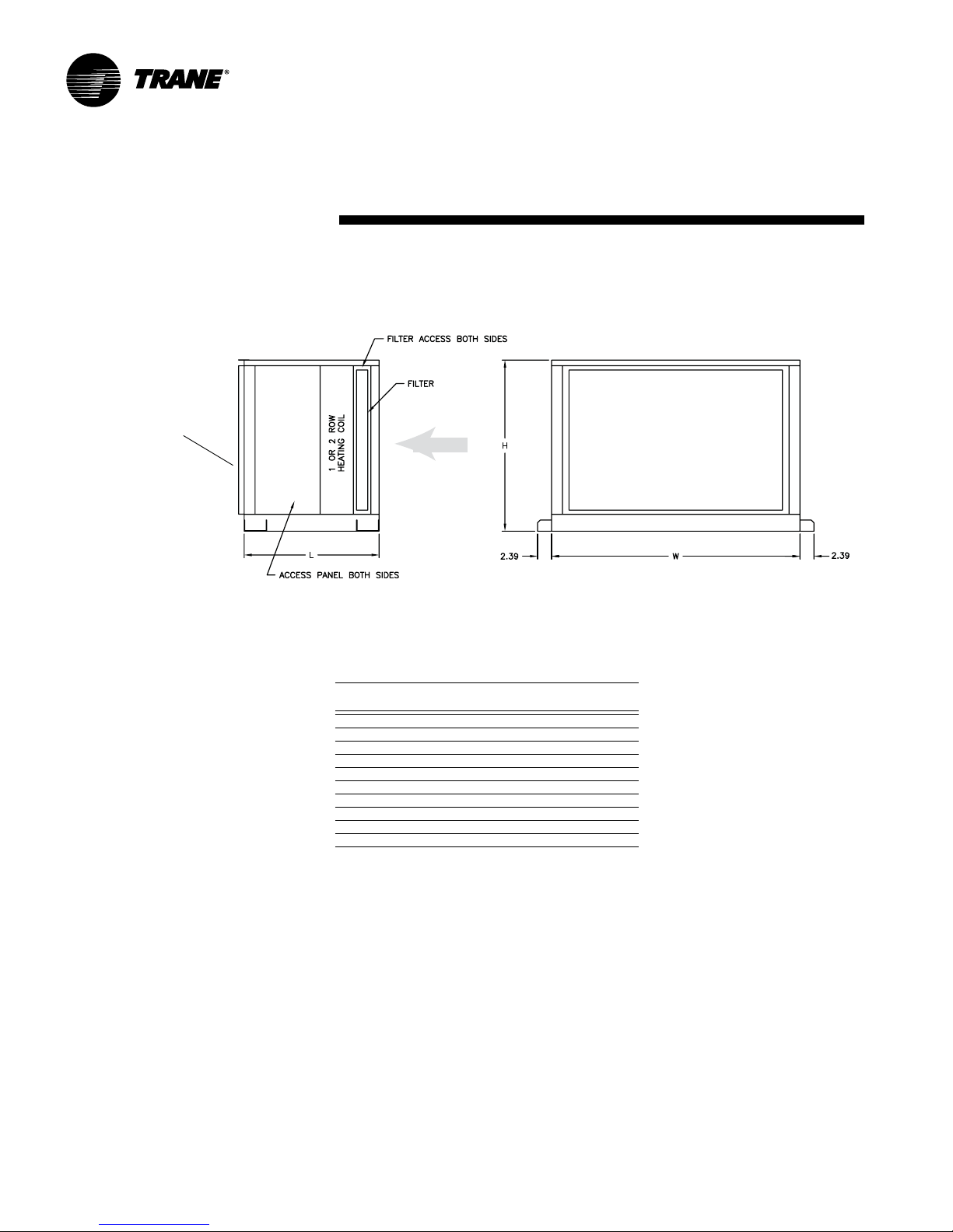
dimensions
Access Section, in.
Note: This is a flanged
edge to secure section
to either the main unit
or another section.
Installation
Airflow
& weights
Note: Access section is only available with a
1 or 2-row heating coil and ships seperate
from main unit.
Access section dimensions & weights, in-lbs.
unit weight
size H L W SW DW
3 24.5 24.3 31.2 69 97
6 30.5 24.3 44.2 100 137
8 34.5 24.3 48.2 106 148
10 34.5 24.3 60.2 119 169
12 42.0 24.3 68.2 162 218
14 42.0 24.3 68.2 157 213
17 52.0 24.3 76.2 204 267
21 52.0 24.3 76.2 196 259
25 59.5 28.3 78.2 248 336
30 59.5 28.3 91.2 271 370
Notes: 1. SW = Single Wall
2. DW = Double Wall
16 LPC-SVX01C-EN
Page 17
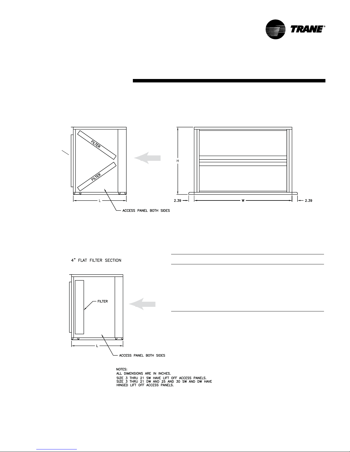
dimensions
Angle Filter Section in.
Note: This
is a flanged
edge to secure
section to
either the main
unit or
another section.
Installation
Airflow
(5.6)
& weights
(5.6)
Note: Angle filter section ships
seperate from main unit.
Flat Filter Section in.
Airflow
Angle & flat filter section dimensions & weights, in-lbs.
unit flat filter angle filter
size H L W SW DW SW DW
3 24.5 21.5 31.2 46 60 50 64
6 30.5 24.0 44.2 64 86 68 90
8 34.5 27.3 48.2 78 107 82 111
10 34.5 25.5 60.2 83 115 89 121
12 42.0 27.3 68.2 112 151 126 165
14 42.0 27.3 68.2 112 151 126 165
17 52.0 29.3 76.2 164 209 179 224
21 52.0 29.3 76.2 164 209 179 224
25 59.5 35.0 78.2 184 250 200 266
30 59.5 35.0 91.2 201 275 217 291
Notes: 1. SW = Single Wall
2. DW = Double Wall
LPC-SVX01C-EN 17
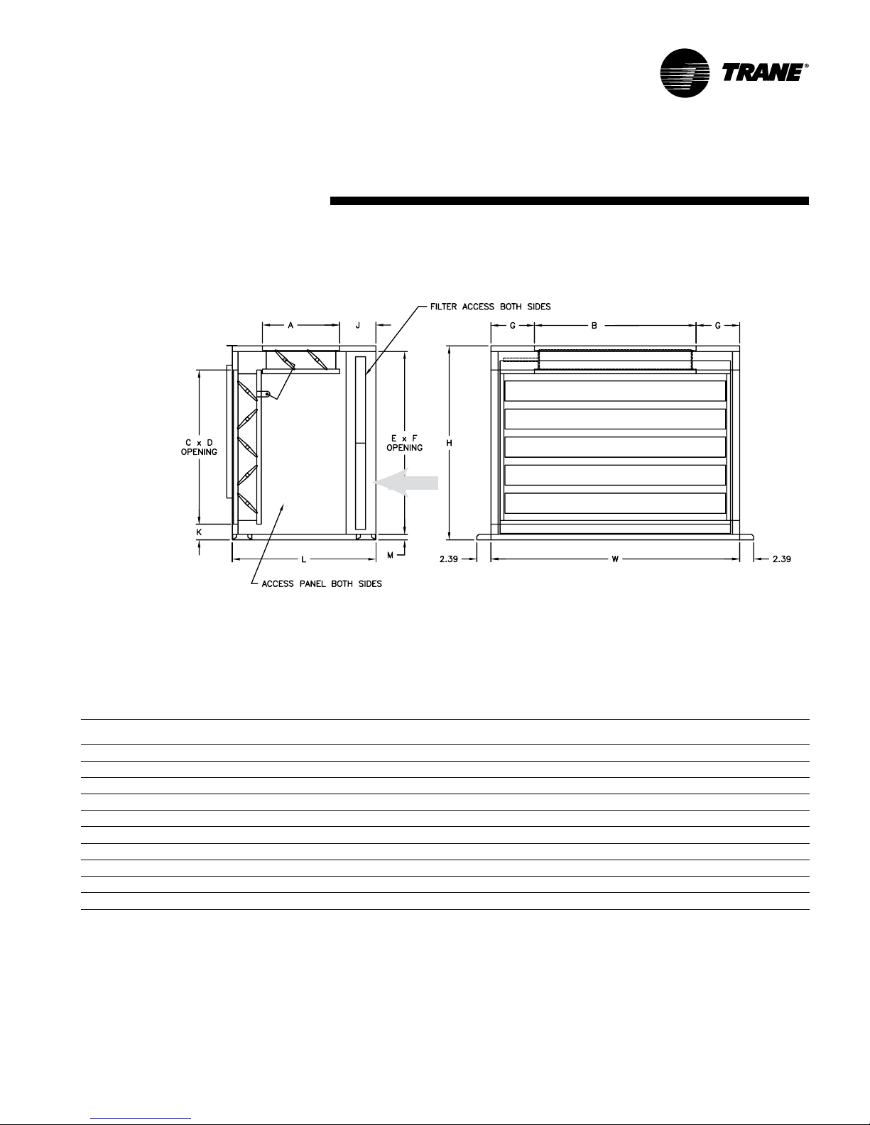
Page 18

dimensions
Damper Section, in.
Note: This is a flanged
edge to secure section
to either the main unit
or another section.
Installation
OPENING OPENING
Airflow
(6.1)
Notes:
All dimensions are in inches.
Damper section ships seperate from main unit.
Linkage between dampers factory installed inside
mixing box on drive side.
& weights
(6.1)
18 LPC-SVX01C-EN
Damper section dimensions & weights, in-lbs.
unit damper weights
size H L W A B C D qty. - size SW DW
3 24.5 21.5 31.2 14.0 16.0 7.6 5.8 2 - 14.0 x 16.0 80 98
6 30.5 24.0 44.2 14.0 29.0 7.6 5.8 2 - 14.0 x 29.0 119 147
8 34.5 27.3 48.2 19.7 26.0 11.1 5.8 2 - 19.7 x 26.0 135 170
10 34.5 25.5 60.2 14.0 46.0 7.1 5.8 2 - 14.0 x 46.0 168 208
12 42.0 27.3 68.2 19.7 37.0 15.6 5.8 2 - 19.7 x 37.0 186 237
14 42.0 27.3 68.2 19.7 44.0 12.1 5.8 2 - 19.7 x 44.0 199 248
17 52.0 29.3 76.2 19.7 53.0 11.6 5.8 2 - 19.7 x 53.0 274 340
21 52.0 34.0 76.2 25.5 53.0 11.6 5.8 2 - 25.7 x 53.0 309 376
25 59.5 35.0 78.2 25.5 58.0 10.1 6.0 2 - 25.7 x 58.0 318 399
30 59.5 35.0 91.2 25.5 68.0 11.6 6.0 2 - 25.7 x 68.0 355 447
Notes: 1. SW = Single Wall
2. DW = Double Wall
Page 19
dimensions
Face & Bypass Section, in.
Note: This is a flanged
edge to secure section
to either the main unit
or another section.
Installation
OPENING
Airflow
& weights
OPENING
Notes:
All dimensions are in inches.
Damper section ships seperate from main unit.
Linkage between dampers factory installed inside
mixing box on drive side.
Face & bypass section dimensions & weights, in-lbs.
unit face bypass weights
size H L W A B C D E F G J K M damper damper SW DW
3 24.5 23.5 31.2 14.0 16.0 14.0 26.0 22.5 28.7 7.6 5.6 5.3 1.0 14.0 x 27.0 14.0 x 16.0 94 111
6 30.5 26.0 44.2 14.0 29.0 19.7 39.0 28.5 41.7 7.6 7.4 4.6 1.0 19.7 x 40.0 14.0 x 29.0 140 165
8 34.5 28.3 48.2 19.7 26.0 25.5 43.0 32.5 45.6 11.1 4.6 3.8 1.0 25.5 x 44.0 19.7 x 26.0 159 188
10 34.5 26.5 60.2 14.0 46.0 25.5 55.0 32.5 57.6 7.1 7.6 3.8 1.0 25.5 x 56.0 14.0 x 49.0 198 231
12 42.0 28.3 68.2 19.7 37.0 31.2 63.0 40.0 65.7 15.6 4.6 4.6 1.0 31.2 x 64.0 19.7 x 37.0 220 260
14 42.0 28.3 68.2 19.7 44.0 31.3 63.0 40.0 65.7 12.1 4.6 4.6 1.0 31.2 x 64.0 19.7 x 44.0 235 274
17 52.0 32.3 76.2 19.7 53.0 42.7 71.0 50.0 73.6 11.6 7.6 3.9 1.0 42 x 72.0 19.7 x 53.0 323 371
21 52.0 35.0 76.2 25.5 53.0 42.7 71.0 50.0 73.6 11.6 4.6 3.9 1.0 42.72 x 72.0 25.5 x 53.0 365 417
25 59.5 37.0 78.2 25.5 58.0 48.5 74.0 53.0 74.0 10.1 5.2 6.4 4.5 48.47 x 74.0 25.5 x 58.0 375 437
30 59.5 37.0 91.2 25.5 68.0 48.5 87.0 53.0 87.0 11.6 5.2 6.4 4.5 48.47 x 87.0 25.5 x 68.0 419 489
Notes: 1. SW = Single Wall
2. DW = Double Wall
LPC-SVX01C-EN 19
Page 20
dimensions
Installation
Electric Heat Section
Electric Heat Section Dimensions & Weights, in-lbs.
Unit
Size H W A B C D Weight
3 24.5 18.0 12.0 10.4 9.3 12.1 34.0
6 30.5 21.0 16.0 13.6 12.3 8.9 38.0
8 34.5 24.5 16.0 13.6 15.8 9.9 44.0
10 34.5 27.5 20.0 16.0 18.8 11.5 62.0
12 42.0 27.8 20.0 19.0 19.0 13.5 66.0
14 42.0 30.8 20.0 19.0 22.0 13.5 69.0
17 52.0 28.6 20.0 24.9 19.9 7.6 73.0
21 52.0 33.6 20.0 24.9 24.9 7.6 77.0
25 59.5 32.0 20.0 25.3 23.3 7.3 79.0
30 59.5 35.1 20.0 28.3 26.4 4.2 82.0
CUSTOMER ELECTRICAL
CONNECTION LOCATION &
SIZE TO BE DETERMINED BY
TUTCO
& weights
20 LPC-SVX01C-EN
Page 21
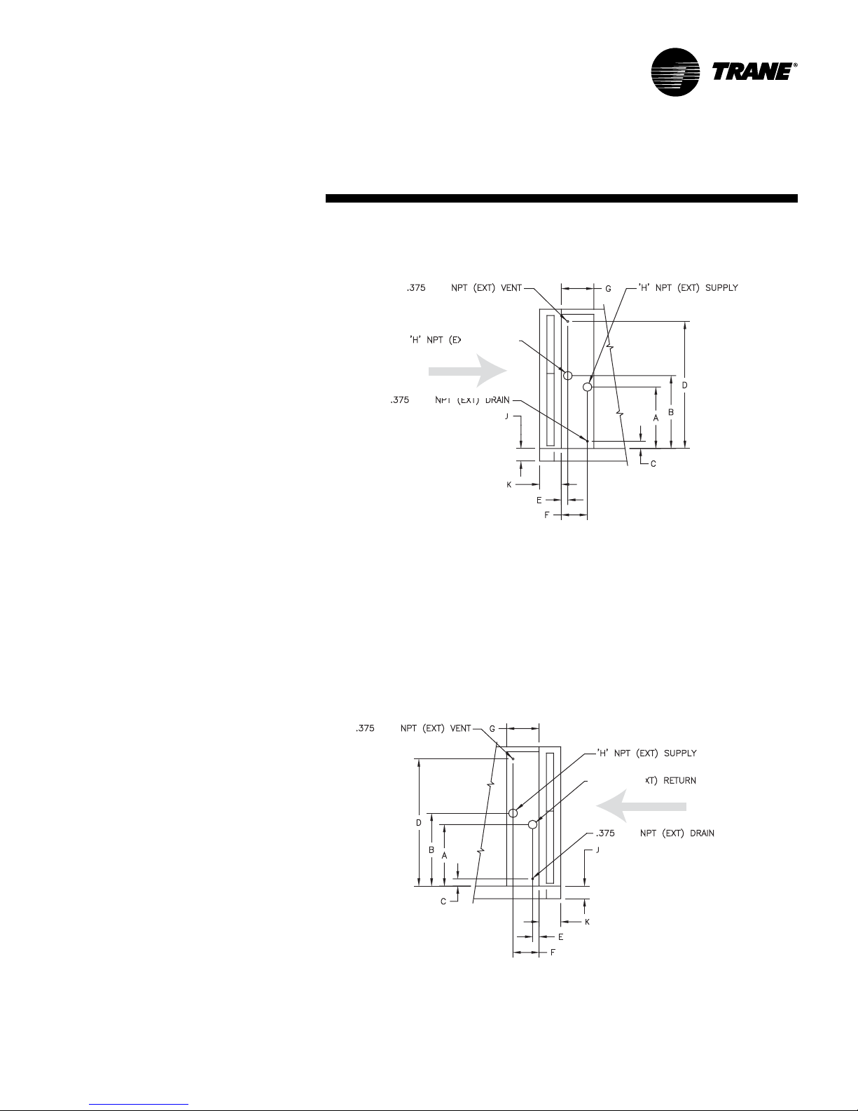
dimensions
Water Coil Connections
Installation
left hand
AIR FLOW
& weights
right hand
Note: J = 3.1” on unit sizes 3 and 6
K = 6.1” on unit sizes 3–21
= 3.6” on unit sizes 8–21
= 4.6” on unit sizes 25 & 30
= 8.1” on unit sizes 25 & 30
AIR FLOW
LPC-SVX01C-EN 21
Page 22

dimensions
Installation
& weights
Water coil connections, in.
unit size A B C D A B C D E F G H
one-row coil
38
611
8, 10 13 5/
12, 14 17 5/
17, 21 22 5/
25, 30 25 3/
two-row coil
37
6 10 13/
8, 10 13 5/
12, 14 17 20 1/
17, 21 22 25 1/
25, 30 25 1/
four-row coil
37
6 10 13/
8, 10 13 5/
12, 14 17 20 1/
17, 21 22 25 1/
25, 30 25 1/
six-row coil
37
6 10 13/
8, 10 13 5/
12, 14 17 20 1/
17, 21 22 25 1/
25, 30 25 1/
eight-row coil
37
6 10 13/
8, 10 13 5/
12, 14 17 20 1/
17, 21 22 25 1/
25, 30 25 1/
left hand connections only right hand connections only
5
/
8
1
/
8
8
16
16
8
5
/
8
16
16
8
5
/
8
16
16
8
5
/
8
16
16
8
5
/
8
16
16
8
11 11/
14 3/
16 11/
20 3/
25 3/
28 5/
10 13/
13 7/
16 3/
28 3/
10 13/
13 7/
16 3/
28 3/
10 13/
13 7/
16 3/
28 3/
10 13/
13 7/
16 3/
28 5/
16
16
16
8
8
8
16
8
8
8
8
16
16
8
8
8
8
16
16
8
8
8
8
16
16
8
8
8
8
16
2 18 5/
2 23 5/
2 28 5/
2 35 13/
2 45 13/
2 5/
8
1 3/
8
16
16
16
16
16
51 3/824 13/
17 8 7/
2 22 5/810 13/
2 27 5/
2 35 1/
2 45 1/
2 51 3/
2 5/
18 5/
8
16
2 22 5/810 13/
2 27 5/
2 35 1/
2 45 1/
2 51 3/
2 5/
18 5/
8
16
2 22 5/810 13/
2 27 5/
2 35 1/
2 45 1/
2 51 3/
2 5/
18 5/
8
16
2 22 5/810 13/
2 27 5/
2 35 1/
2 45 1/
2 51 3/
7 7/
10 3/
12 7/
16 11/
21 11/
13 5/
8
8
8
8
17 20 1/
22 25 1/
25 1/
8 7/
13 5/
8
8
8
8
17 20 1/
22 25 1/
25 1/
8 7/
13 5/
8
8
8
8
17 20 1/
22 25 1/
25 1/
8 7/
13 5/
8
8
8
8
17 20 1/
22 25 1/
25 1/
11 1/
8
13 5/
8
16 1/
8
19 13/
16
24 13/
16
27 7/
16
8
13 7/
16
16 3/
16
28 5/
8
8
13 7/
16
16 3/
16
28 5/
8
8
13 7/
16
16 3/
16
28 5/
8
8
13 7/
16
16 3/
16
28 5/
8
1 3/
8
1 3/
8
1 3/
8
1 3/
16
1 3/
16
8
12 2 5/
8
8
8
8
16
12 2 5/
8
8
8
8
16
12 2 5/
8
8
8
8
16
12 2 5/
8
8
8
8
16
17 5/81 11/
8
22 5/81 11/
8
27 5/81 11/
8
35 1/
8
8
2 50 13/
8
8
45 1/
8
16
18 5/161 13/
2 22 5/81 13/
2 27 5/81 13/
2 35 1/
2 45 1/
2 51 3/
8
2 22 5/
2 27 5/
2 35 1/
2 45 1/
2 51 3/
8
8
8
8
18 5/
16
8
8
8
8
8
18 5/161 13/
2 22 5/81 13/
2 27 5/81 13/
2 35 1/81 13/
2 45 1/81 13/
2 51 3/81 13/
18 5/161 13/
8
2 22 5/81 13/
2 27 5/81 13/
2 35 1/81 13/
2 45 1/81 13/
2 51 3/81 13/
3 11/
16
3 11/
16
3 11/
16
1 1/
2
1 1/
2
24 1/
16
16
16
1 1/23 13/
1 1/23 13/
1 7/
8
47 3/
47 3/
47 3/
47 3/
47 3/
47 3/
7 3/
16
7 3/
16
7 3/
16
7 3/
16
7 3/
16
7 3/
16
16
16
16
16
16
16
3 7/
3 7/
3 5/
3 5/
3 5/
4 5/
9 3/
9 3/
9 3/
9 3/
9 3/
9 3/
5 3/
16
16
16
8
8
2
8
8
8
16
16
8
16
16
16
16
16
16
16
16
16
16
16
16
8
8
8
8
8
8
8
5 3/
8
5 3/
8
5 3/
8
5 3/
8
6 1/
2
5 3/
8
5 3/
8
5 3/
8
5 3/
8
5 3/
8
6 1/
2
91
91
91
92
92
92
91
91
91
92
92
92
11 3/
16
11 3/
16
11 3/
16
11 3/
16
11 3/
16
11 3/
16
1 1/
1 1/
1 1/
1 1/
1 1/
1 1/
2 1/
1 1/
1 1/
1 1/
2 1/
2 1/
2
2
2
2
2
2
2
2
2
2
2
2
1
/
2
1
/
2
1
/
2
1
/
2
1
/
2
1
/
2
1
/
2
1
/
2
1
/
2
1
/
2
2
2
2
2
2
2
22 LPC-SVX01C-EN
Page 23
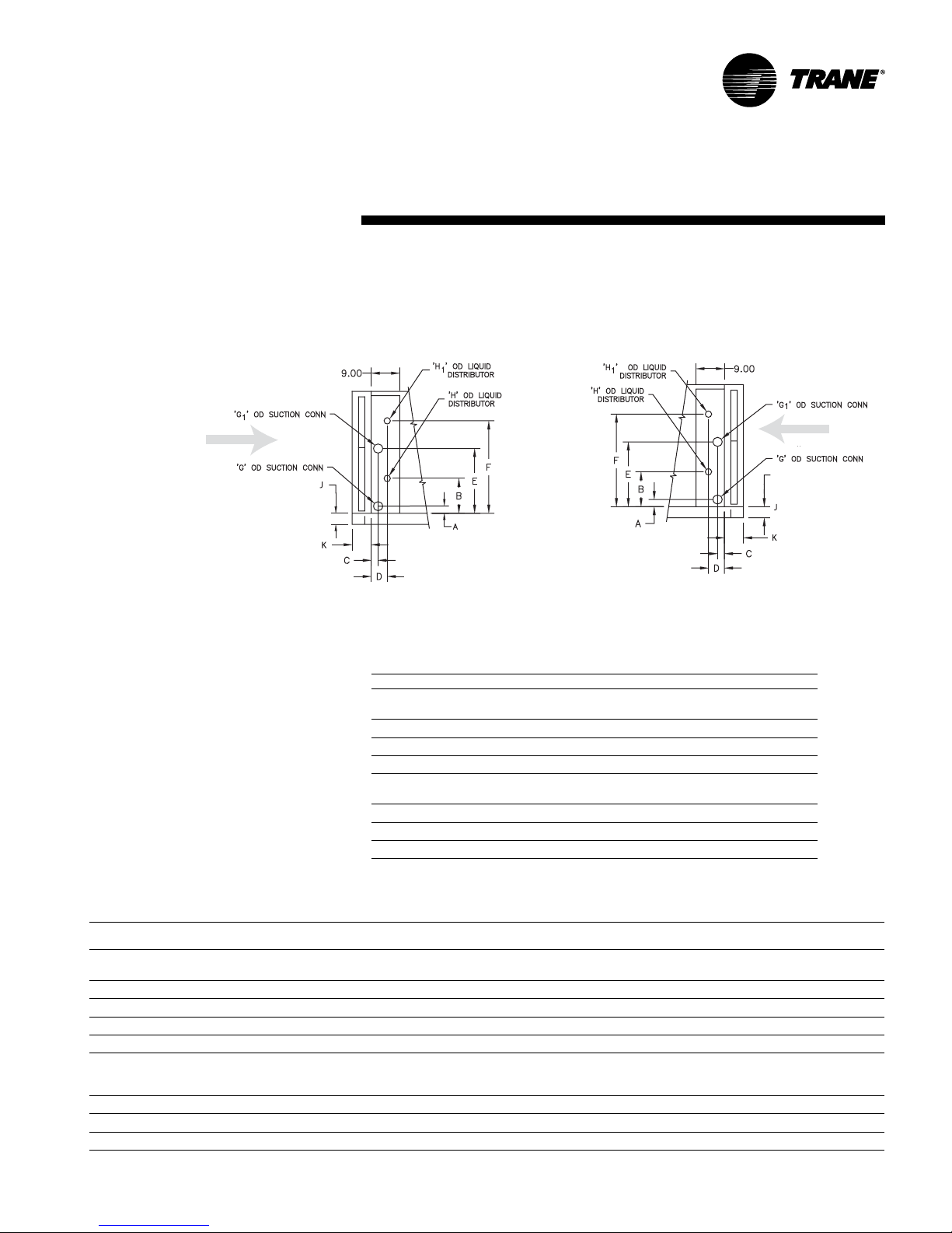
dimensions
Installation
DX Coil Connections
single circuit coils for unit sizes 3 –10 and horizontal face split coils for unit sizes 12 – 25
left hand
AIR FLOW
NOTE: DX COIL CONNECTIONS ARE SWEAT STYLE
& weights
right hand
AIR FLOW
Single circuit DX coil connections, unit sizes 3 - 10, in.
unit size A B C D (LH) D (RH) G H J K
four-row coil,
3 2 3/810 5/1645 1/87 3/161 3/8 5/83 1/86 1/
6 2 3/817 11/1645 1/87 3/161 3/8 7/83 1/86 1/
8 2 3/818 13/1645 1/87 3/161 3/8 7/83 5/86 1/
10 2 1/218 3/1645 1/87 3/161 5/8 7/83 5/86 1/
six-row coil, 1/4” distributor
3 2 3/811 1 13/162 7/851 3/8 7/83 1/86 1/
6 2 3/817 11/161 13/162 7/851 3/8 7/83 1/86 1/
8 2 3/819 5/161 13/162 7/851 3/81 1/83 5/86 1/
10 2 1/219 1 13/162 7/851 5/81 3/83 5/86 1/
Note: Single circuit DX coils on unit sizes 3 – 10 have one distributor.
3
/16” distributor
8
8
8
8
8
8
8
8
Horizontal face split circuit DX coil connections, unit sizes 8 – 25, in.
unit
size A B C D (LH) D (RH) E F G G1 H H1 J K
four-row coil,
82
10 2 3/
12, 14 1 7/
17, 21 1 7/
25 1 7/
six-row coil, 1/4” distributor
82
10 2 3/
12, 14 2 3/
17, 21 2 3/
3
/16” distributor
3
/
8
8
8
8
8
3
/
8
8
8
8
8 1/
8
8 1/
8
12 5/
8
17 5/
8
18 5/
16
8 13/
16
13/
16
13 1 13/
18 3/
16
45 1/
45 1/
45 1/
45 1/
45 5/
1 13/
16
1 13/
16
16
1 13/
16
2 7/
2 7/
2 7/
2 7/
7 3/
8
7 3/
8
7 3/
8
7 3/
8
7 3/
16
8
8
8
8
17 3/
16
14 7/
16
16
16
16
19 7/
27 1/
5 17 3/
5 14 7/
519
525421
22 13/
8
22 3/81 3/81 3/
8
31 1/81 3/81 3/
8
16
1 3/81 3/
25 41 3/81 5/81 5/
43 5/
2
22 3/81 3/81 3/
8
22 3/81 3/81 5/
8
7
/
31 3/81 3/81 3/
8
16
1 5/81 5/
5
/81 5/
5/
8
7/
8
7/
8
7/
8
7/
8
7/
8
7/
8
1 1/
8
1 1/
8
5/
8
8
8
8
8
7/
8
7/
8
7/
8
1 1/
8
3 5/
8
7
/
8
7
/
8
7
/
8
7
/
8
8
8
8
8
3 5/
3 5/
3 5/
4 5/
3 5/
3 5/
3 5/
3 5/
8
8
8
8
8
8
8
8
8
6 1/
6 1/
6 1/
6 1/
8 1/
6 1/
6 1/
6 1/
6 1/
8
8
8
8
8
8
8
8
8
LPC-SVX01C-EN 23
Page 24
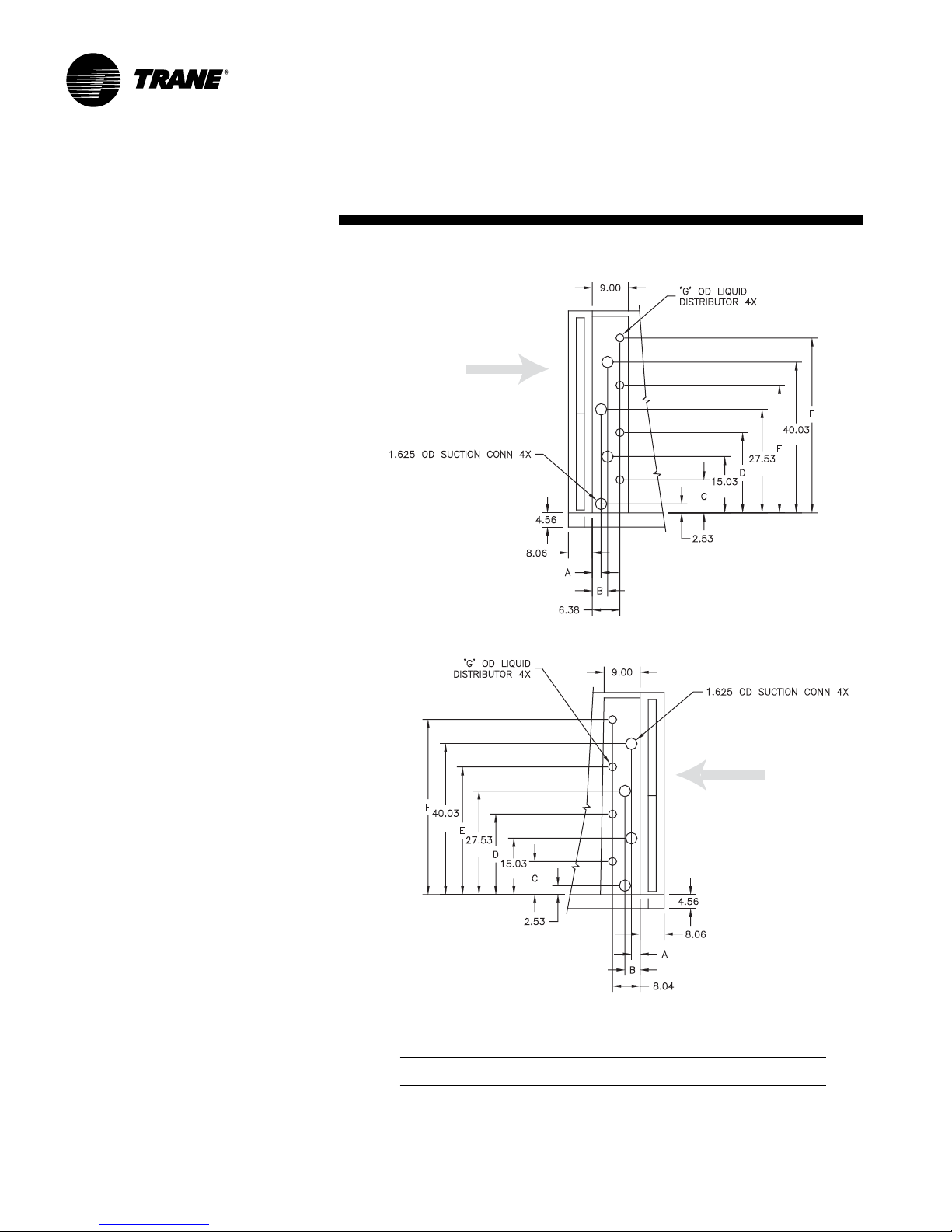
dimensions
DX Coil Connections
horizontal face split circuit coils for unit size 30
Installation
left hand
AIR FLOW
& weights
NOTE: DX COIL CONNECTIONS ARE SWEAT STYLE
right hand
AIR FLOW
NOTE: DX COIL CONNECTIONS ARE
SWEAT STYLE
Horizontal face split circuit DX coil connections, unit size 30, in.
ABCDE F G
four-row coil, 3/16” distributor
3 1/84 13/1611 1/823 5/836 1/848 5/8 7/
six-row coil, 1/4” distributor
12 5/811 7/824 3/836 7/849 3/81 3/
Note: Horizontal face split circuit DX coils on unit size 30 has four distributors.
8
8
24 LPC-SVX01C-EN
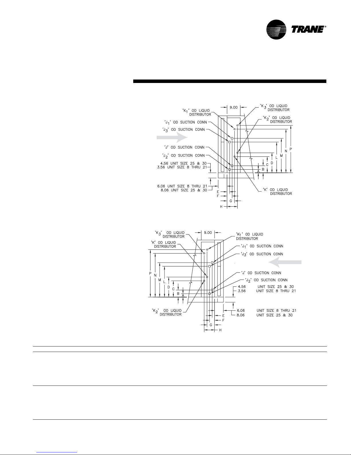
Page 25
dimensions
DX Coil Connections
intertwined coils unit sizes 8 – 30
NOTE: DX COIL CONNECTIONS ARE SWEAT STYLE
Installation
left hand
AIR FLOW
right hand
& weights
AIR FLOW
Intertwined circuit DX coil connections, unit sizes 8 – 30, in.
unit size A B C D E F G H J J
four-row coil,
82
10 2
12,14 2
17, 21 2
25 2 3/84 7/817 1/220 3 3/164 11/165 5/167 5/16 7/81 3/81 3/81 3/8 7/8 7/8 7/8 7/827 3/829 7/842 1/245
30 2 1/23 13/1618 7/820 1/83 1/84 7/86 3/168 3/161 5/81 5/81 5/81 5/8 7/8 7/8 7/8 7/827 1/228 13/1643 7/845 1/
six-row coil, 1/4” distributor
82
10 2
12,14 2
17, 21 2
25 2
30 2 1/23 13/1619 11/1620 7/812 5/86 3/168 3/161 5/81 5/81 5/81 5/81 3/81 3/81 3/81 3/827 1/228 13/1644 11/1645 7/
Note: DX intertwined coils, on unit sizes 8 – 14 have two distributors. Unit sizes 17 – 30 have four distributors.
3
/16” distributor
3
/86 3/1618 3/1614 1/83 3/164 11/165 5/167 5/161 3/8-- 1 3/8-- 5/8-- 5/8-- -- -- -- -
3
/84 7/820 1/822 5/83 3/164 11/165 5/167 5/161 3/8-- 1 3/8-- 7/8-- 7/8-- -- -- -- --
3
/84 7/822 13/1619 11/163 3/164 11/165 5/167 5/161 3/8-- 1 3/8-- 7/8-- 7/8-- -- -- -- --
3
/84 7/817 1/214 7/83 3/164 11/165 5/167 5/161 3/81 3/81 3/81 3/8 5/8 5/8 7/8 5/824 7/827 3/836 1/838 5/
3
/86 3/1618 5/814 7/812 5/83 3/165 3/161 3/8-- 1 3/8-- 7/8-- 7/8-- -- -- -- --
3
/84 7/820 1/822 5/812 5/83 3/165 3/161 3/8-- 1 3/8-- 7/8-- 7/8-- -- -- -- --
3
/84 7/823 3/1619 13/1612 5/83 3/165 3/161 3/8-- 1 3/8-- 7/8-- 1 1/8-- -- -- -- --
3
/84 7/817 1/215 5/1612 5/83 3/165 3/161 3/81 3/81 3/81 3/8 7/8 7/8 7/8 7/824 7/827 3/836 1/239
3
/84 7/817 1/220 1 2 5/83 3/165 3/161 3/81 3/81 3/81 3/8 7/8 7/8 7/8 7/827 3/829 7/842 1/245
J2J
1
KK1K2K
3
LM N P
3
8
8
8
LPC-SVX01C-EN 25
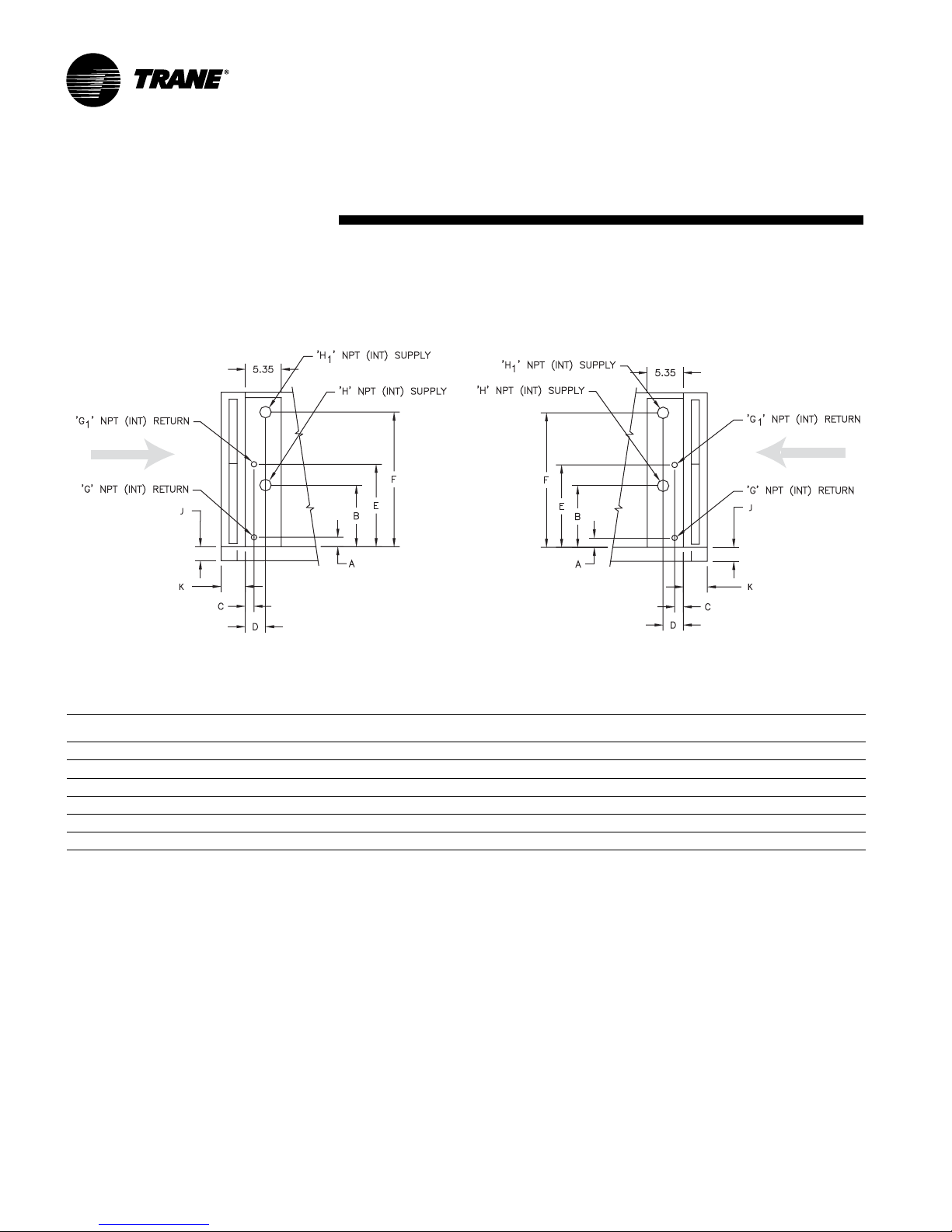
Page 26
dimensions
Steam Coil Connections
left hand
AIR FLOW
Installation
right hand
& weights
AIR FLOW
Steam coil connections, in.
unit
size A B (LH) B (RH) C D E F (LH) F (RH) G G
34
6 4 13 3/
8, 10 3 3/
12, 14 2 3/
17, 21 2 3/
25, 30 2 5/
Note: Unit sizes 17 – 30 with steam coils are two stacked coils.
1
/
10 7/
2
15 7/
16
18 3/
8
14 7/
16
15 12 1 5/
16
7 7/
8
10 3/
8
12 7/
8
18 3/
16
11 7/
8
1 5/
8
1 5/
8
1 5/
8
1 5/
16
1 5/
8
2 13/
16
2 1/
16
2 1/
16
2 1/
16
2 1/
16
2 1/
16
-- -- -- 1 -- 1 1/
16
-- -- -- 1 -- 2 -- 3 1/
2
-- -- -- 1 5/
2
-- -- -- 1 5/
2
28 37 3/
2
2
27 13/1640 1/
8
2
34 3/
37 1/
8
2
1 5/
1 5/
16
16
16
16
HH1JK
1
-- 2 1/
2
2
-- 3 1/
-- 3 5/
-- 3 -- 3 5/
12
1 5/
1
/
23
2
2 1/
16
2 1/
2
4 5/
2
6 1/
8
8
8
8
5
/
8
8
6 1/
6 1/
6 1/
6 1/
8 1/
8
8
8
8
8
8
26 LPC-SVX01C-EN
Page 27
pre-installation
WARNING
Hazardous Voltage w/Capacitors!
Disconnect all electric power,
including remote disconnects and
discharge all motor start/run
capacitors before servicing.
Follow proper lockout/tagout
procedures to ensure the power
cannot be inadvertently
energized. For variable frequency
drives or other energy storing
components provided by Trane or
others, refer to the appropriate
manufacturer’s literature for
allowable waiting periods for
discharge of capacitors. Verify
with an appropriate voltmeter
that all capacitors have
discharged. Failure to disconnect
power and discharge capacitors
before servicing could result in
death or serious injury.
Receiving and Handling
Upon delivery, inspect all components for
possible shipping damage. See the
Receiving Checklist section for detailed
instructions. Trane recommends leaving
units and accessories in their shipping
packages/skids for protection and ease of
handling until installation.
Shipping Package
Packaged Climate Changer air handlers
ship assembled on skids with protective
coverings over the coil and discharge
openings. Optional accessory sections
ship attached to one another on a
separate skid for unit sizes except 25 and
30. For those sizes, up to two accessory
sections may ship on one skid.
Ship-Separate Accessories
Field-installed sensors ship separately
inside the unit’s main control panel.
Receiving Checklist
Complete the following checklist
immediately after receiving unit
shipment to detect possible shipping
damage.
Inspect individual cartons before
accepting. Check for rattles, bent
carton corners, or other visible
indications of shipping damage.
Installation
If a unit appears damaged, inspect it
immediately before accepting the
shipment. Manually rotate the fan
wheel to ensure it turns freely. Make
specific notations concerning the
damage on the freight bill. Do not
refuse delivery.
Inspect the unit for concealed
damage before it is stored and as
soon as possible after delivery.
Report concealed damage to the
freight line within the allotted time
after delivery. Check with the carrier
for their allotted time to submit a
claim.
Do not move damaged material from
the receiving location. It is the
receiver’s responsibility to provide
reasonable evidence that concealed
damage did not occur after delivery.
Do not continue unpacking the
shipment if it appears damaged.
Retain all internal packing, cartons,
and crate. Take photos of damaged
material.
Notify the carrier’s terminal of the
damage immediately by phone and
mail. Request an immediate joint
inspection of the damage by the
carrier and consignee.
Notify your Trane representative of
the damage and arrange for repair.
Have the carrier inspect the damage
before making any repairs to the unit.
Compare the electrical data on the
unit nameplate with the ordering and
shipping information to verify the
correct unit is received.
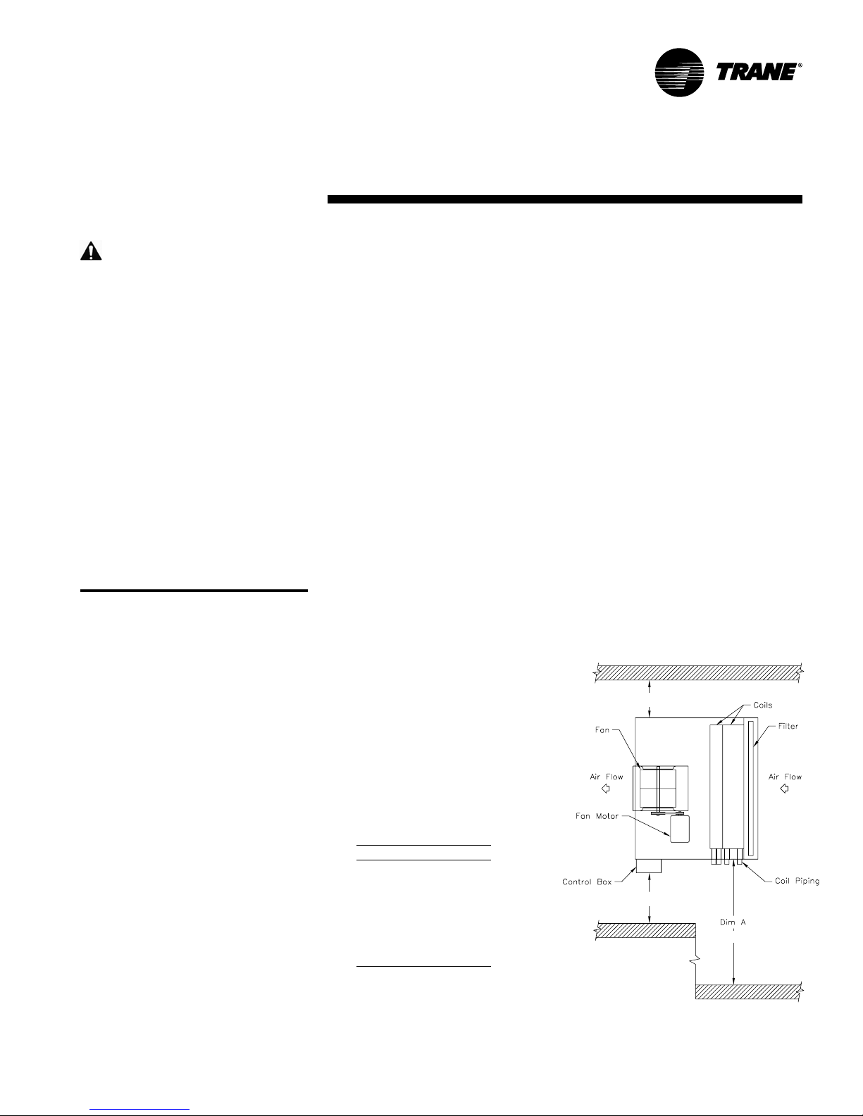
Table I-PC-1. Service
Requirements, in. (cm)
Unit Size Dimension A
3 43 (109)
6 56 (142)
8 59 (150)
10 & 12 71 (180)
14 79 (201)
17 74 (188)
21 86 (218)
25
30
Figure I-PC-1. Top view of Packaged climate changer unit showing recommended
service and code clearances.
considerations
Installation Preparation
Before installing the unit, consider the
following unit location recommendations
to ensure proper unit operation.
1. Verify the floor or foundation is level.
Shim or repair as necessary. To
ensure proper unit operation, install
the unit level (zero tolerance) in both
horizontal axes. Failure to level the
unit properly can result in condensate
management problems, such as
standing water inside the unit.
2. Allow adequate service and code
clearances as recommended in
“Service Access” section. Position
the unit and skid assembly in its final
location.
3. Consider coil piping and condensate
drain requirements. Allow room for
proper ductwork and electrical
connections. Support all piping and
ductwork independently of the unit to
prevent excess noise and vibration.
Service Access
See Table I-PC-1 below and Figure I-PC-1
for recommended service and code
clearances.
3 Ft.
3 Ft.
3
3
LPC-SVX01C-EN 27
Page 28
pre-installation
Rigging and Handling
Before preparing the unit for lifting,
estimate the approximate center of
gravity for lifting safety. Unit weight may
be unevenly distributed with more
weight in the coil area. Approximate unit
weights are given in the Dimensions and
Weights section and on the unit
nameplate.
Before hoisting the unit into position, use
a proper rigging method such as straps,
slings, or spreader bars for protection
and safety. Always test-lift the unit (at
least 24 inches) to determine the exact
unit balance and stability before hoisting
it to the installation location.
WARNING
Improper Unit Lift!
Test lift unit approximately 24 inches
to verify proper center of gravity lift
point. To avoid dropping unit,
reposition lifting point if unit is not
level. Failure to properly lift unit could
result in death, serious injury, or
possible equipment or property-only
damage.
Installation
Skid Removal
The unit ships on skids that provide forklift
locations from the front or rear. The skid
allows easy maneuverability of the unit
during storage and transportation.
Remove the skids before placing the unit
in its permanent location.
Remove the skids using a forklift or jack.
Lift one end of the unit off of the skids.
Vibration isolators for external isolation
are field supplied. See Figure I-PC-1 for
installation recommendations.
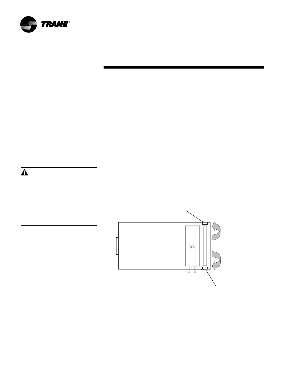
Rotating Filter Door Swing
The unit ships with the fillter doors in a
downstream configuration. To allow the
doors to swing in an upstream
configuration, follow the steps listed in the
figure below.
Step 1:
Remove screws
holding hinges to
fixed panel near
coil
considerations
Unit Location
Recommendations
When selecting and preparing the
installation location, follow these
recommendations.
1. Consider the unit weight. Reference the
unit weight on the unit nameplate or in
the Dimensions and Weights section.
2. Allow sufficient space for
recommended clearances, access
panel removal, and maintenance
access. Refer to Figure I-PC-1.
3. The installer must provide threaded
suspension rods for ceiling mounted
units. All units must be installed level.
4. Coil piping and condensate drain
requirements must be considered.
Allow room for proper ductwork and
electrical connections. Support all piping
and ductwork independently of unit to
prevent excess noise and vibration.
28 LPC-SVX01C-EN
Step 2: Repeat Step 1
on opposite side
of unit
Figure I-PC-2. Rotating Filter Door Swing
Swap doors to their opposite
Step 3:
sides. Hinges will now be
located on the upstream side
of the fan
Step 4:
Use self drilling screws
removed in steps 1 & 2
to secure hinges to
adjacent upstream panel
Page 29
pre-installation
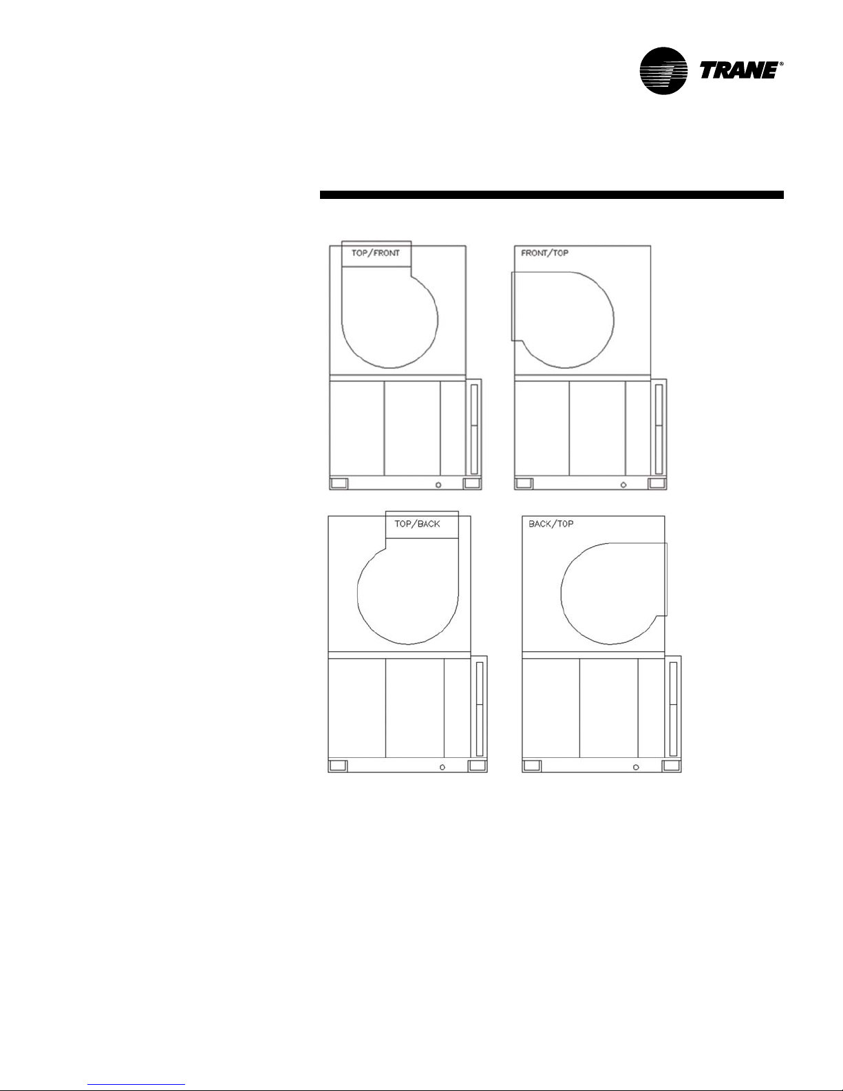
Fan Discharge Conversion
The LPC Vertical Unit can be ordered in
four discharge configurations:
Top/Front, Front/Top, Top/Back, and Back/
Top Figure I-PC-4. Discharge
Configurations. Field conversions from
one configuration to another can be
made for sizes 8 through 21 by modifying
certain parts of the cabinet and by
rotating the fan. Also, if changing from a
front or back discharge to a top discharge
configuration, a duct extension will need
to be added.
For sizes 3 and 6 a new fan assembly will
be needed.
There are some differences between
single-wall construction cabinets with
fiberglass insulation and
double-wall construction cabinets with
foam insulation that will drive some
minor differences in some of the steps
required for a field conversion.
But overall the basic steps are the same
for both.
1. Disconnect power from the unit
2. Remove access doors.
3. Remove the screws inside the
cabinet along the top of the coil that
secure the coil to the cabinet roof
4a. If top discharge and no internal
isolation remove screws securing
duct that connects the fan to the roof
b. If top discharge with internal isolation,
duct is not mechanically secured to
the fan so roof & duct can be
removed as one piece.
c. Remove roof
5a. If horizontal (front or back) discharge
and no internal isolation, remove
screws securing fan housing to
cabinet
b. If horizontal (front or back) discharge
with internal isolation loosen and
remove j-bolt securing fan housing to
cabinet.
c. Remove front and back panel.
6. Loosen nuts/bolts securing sliding
motor base in place and loosen nuts
on belt tensioning bolt.
7. Remove v-belt(s)
8. Detach fan from the base and rotate
to the desired discharge position.
Installation
Figure I-PC-4. Discharge Configurations
9. It may be necessary to remove and
reinstall the fan shaft on the opposite
side depending on the new discharge
position. Loosen set screws on the
fan bearings that hold the shaft in
place. Loosen set screw holding fan
in place. Remove shaft from the fan
and reinstall so that the driven end is
on the opposite side.
10. Reattach fan to the base
considerations
11. Reattach v-belt, tighten, and secure
sliding motor base in place. Because
the distance between the motor shaft
and the fan shaft may change, it may
be necessary to purchase a new vbelt.
12. Cut a hole in the discharge panel for
the air discharge. For double wall
units cover the exposed foam
insulation at the inside edges of the
hole using the insulation cover
channels installed on the other
discharge panel.
LPC-SVX01C-EN 29
Page 30
pre-installation
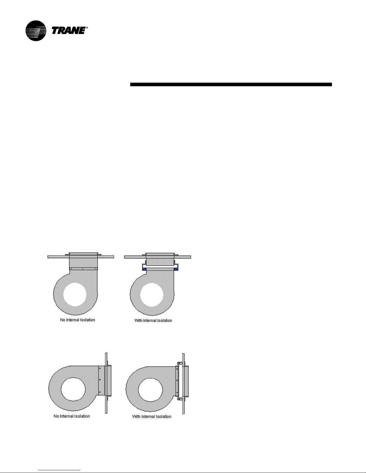
13a. If changing from horizontal discharge
to vertical (such as front/top to top/
front) then a duct extension will need
to be added to join the fan to the roof.
b. On units without internal isolation the
duct extension is secured to the fan
housing with screws. The duct can be
purchased from Service Parts or can
be fabricated in the field.
c. On units with internal isolation the
duct extension is wider at the bottom
to form a gap between and the fan
housing, which is bridged by a flexible
foam gasket. Contact Service Parts
for a duct extension kit. (See Fig. 1)
14a. If changing from vertical to horizontal
(such as top/front to front/top) then
the duct extension will need to be
replaced by mounting angles to join
the fan to the cabinet.
Installation
b. On units without internal isolation the
mounting angles can be secured to
the fan and to the cabinet with
screws. The angles can be purchased
from Service Parts or can be
fabricated in the field.
c. On units with internal isolation the
mounting angles do not extend as far
and do not reach the cabinet panel.
The gap is bridged by a flexible foam
gasket. Also the gasket stays
compressed using a thrust restraint
assembly. Contact Service parts for
angle/gasket kit. (See Fig. 2)
15. Reattach roof
16. Reattach coil to roof support.
17. Reattach front/back panels
18. Reattach access doors.
considerations
Pre-Installation Checklist
Complete the following checklist before
beginning unit installation.
Verify the unit size and tagging with
the unit nameplate.
Make certain the floor or foundation
is level, solid, and sufficient to support
the unit and accessory weights. See
the Dimensions and Weights section.
Level or repair the floor before
positioning the unit if necessary.
Allow minimum recommended
clearances for routine maintenance
and service. Refer to unit submittals
for dimensions.
Allow one and one half fan diameters
above the unit for the discharge
ductwork.
Figure I-PC-5. Contact Service Parts for a Duct Extension Kit
Figure I-PC-6 Service PArts for Angle/Access Kits
30 LPC-SVX01C-EN
Page 31

mechanical
requirementsInstallation
Duct Connections
WARNING
Hazardous Voltage w/Capacitors!
Disconnect all electric power,
including remote disconnects and
discharge all motor start/run
capacitors before servicing. Follow
proper lockout/tagout procedures to
ensure the power cannot be
inadvertently energized. Verify with an
appropriate voltmeter that all
capacitors have discharged. Failure to
disconnect power and discharge
capacitors before servicing could
result in death or serious injury.
Install all air ducts according to the
National Fire Protection Association
standards for the “Installation of Air
Conditioning and Ventilation Systems
other than Residence Type (NFPA 90A)
and Residence Type Warm Air Heating
and Air Conditioning Systems (NFPA
90B).
For units without internal isolation, inlet
and discharge air duct connections to the
unit should be made with a flexible
material minimizing noise and vibration.
Typically, about three inches is needed for
this connection to rigid ductwork.
For units with internal isolation, flexible
material is not required on the inlet and
discharge air duct connections.
Inlet and discharge air duct connections to
the unit should be made with a flexible
material minimizing noise and vibration.
Typically, about three inches is needed for
this connection to rigid ductwork.
Duct turns and transitions must be made
carefully to minimize air friction losses.
Avoid sharp turns and use splitters or
turning vanes when elbows are necessary. Make turns in the same direction of
rotation of the fan. Discharge ductwork
should run in a straight line, unchanged in
size or direction, for at least a distance of
1
/2 fan diameters
1-
Condensate Drain
Connections
The main drain line and the trap must be
the same size as the drain connection.
Refer to Table I-MR-1 for drain line sizes.
Refer to Figure I-MR-1 for a guide to trap
sizing.
Drain traps must be primed. If they are
not, the trap is essentially non-existent
and the drain will likely overflow.
Plug or trap the auxiliary drain connection, if applicable. If the auxiliary drain
connection is left open, air can be drawn
in through the opening. This drawn in air
can cause moisture carryover.
All drain lines downstream of the trap
must flow continuously downhill. If
segments of the line are routed uphill, this
can cause the drain line to become
pressurized. With a pressurized drain
line, the trap can back up into the drain
pan, causing it to overflow.
See Figure I-MR-1 for drain trap recommendations.
CAUTION
Water Damage!
Failure to make adequate condensate
piping may result in water damage to
the equipment or building.
Coil Connections
Hydronic Coils
Hydronic coil options are either one, two,
four, six or eight-row coils with high
efficiency Delta-Flo
are mechanically bonded to ½ inch O.D.
seamless copper tubes. All coils are
specifically designed and circuited for
chilled and hot water use only. All coils
are pressure tested at 450 psi. Threaded
connections are standard.
Proper installation and piping is necessary to enure satisfactory coil operation
and prevent operational damage. Water
inlet and outlet connections protrude
through the coil access panel. Follow
standard piping practices when piping to
the coil.
Steam Coils
Packaged Climate Changer units fitted
with steam coils have labeled holes for
piping penetrations. Check that the coil is
installed correctly and that the unit
installation agrees with the submittals.
Refer to Figure I-MR-2 for typical steam
coil piping.
H = 1” Of Length for Each 1” Of Negative Pressure
+ 1” Additional
J= 1/2 of H
L = H + J + Pipe Dia. + Insulation
™
fins. Aluminum fins
Table I-MR-1. Condensate Piping Sizes
Unit Size 3 6 8 10 12 14 17 21 25 30
Main Drain (in) 0.75 0.75 1.00 1.00 1.00 1.00 1.00 1.00 1.25 1.25
Main Drain (cm) 1.905 1.905 2.54 2.54 2.54 2.54 2.54 2.54 3.175 3.175
Auxiliary Drain (in.) 0.75 0.75 N/A N/A N/A N/A N/A N/A N/A N/A
Auxiliary Drain (cm) 1.905 1.905 N/A N/A N/A N/A N/A N/A N/A N/A
LPC-SVX01C-EN 31
Figure I-MR-1. Recommended drain trap
installation for draw-thru units.
Page 32

mechanical
Coil Connection Recommendations
Follow these recommendations to
prevent possible damage when making
coil connections:
1. Install a ½”15 swing-check vacuum
breaker in the unused condensate
return connection at the top of the
coil. Install this vacuum breaker as
close to the coil as possible.
2. Vent the vacuum breaker to the
atmosphere or pipe it to the return
main at the discharge side of the
steam trap.
Note: A vacuum breaker is mandatory
when the coil is controlled by a modulating steam supply or two-position (on/off)
automatic steam supply valve.
WARNING
Hazardous Pressures!
Installation
Code of System Components in Piping Diagram
FT Float and thermostatic steam trap
BT Bucket steam trap
GV Gate valve
OV Automatic two-position (on-off) control valve
TV Automatic three-way control valve
VB Vacuum breaker
CV Check valve
ST Strainer
AV Automatic or manual air vent
requirements
If a heat source is required to raise
the tank pressure during removal of
refrigerant from cylinders, use only
warm water or heat blankets to raise
the tank temperature. Do not exceed
a temperature of 150
any circumstances apply direct
flame to any portion of the cylinder.
Failure to follow these safety precautions could result in a violent explosion, which could result in death
or serious injury.
The condensate return line must be
piped full size of the condensate trap
connection, except for a short nipple
screwed directly into the coil headers
condensate return trapping. Do not bush
or reduce the coil return tapping size.
Proper Steam Trap Installation
Proper steam trap selection and
installation is necessary for satisfactory
coil performance and service life. For
installation, use the following steps:
1. Install the steam trap discharge 12
inches below the condensate return
connection to provide sufficient head
pressure to overcome trap losses
and ensure complete condensate
removal. Use float and themostatic
traps with atmospheric pressure
gravity condensate return, with
automatic controls or when there is a
possibility of low pressure steam.
°
F. Do not, under
Figure I-MR-2. Typical Piping for Steam Coils
Float and thermostatic traps are
recommended because gravity drain
and continuous discharge operation.
2. Trap each coil separately to prevent
holding up condensate in one or
more of the coils.
3. Install strainers as close as possible
to the inlet side of the trap.
4. Use a V-Port modulating valve to
obtain gradual modulation of the coil
steam supply.
5. Do not modulate systems with
overhead or pressurized returns
unless the condensate is drained by
gravity into a receiver, vented to
atmosphere, and returned to the
condensate pump.
6. Slowly turn the steam on full for at
least ten minutes before opening the
fresh air intake on units with fresh air
dampers.
7. Pitch all supply and return steam
piping down 1-inch per 10 feet in the
direction of the steam or condensate
flow.
8. Do not drain the steam mains or
take-offs through the coils. Drain the
mains ahead of the coil through a
steam trap to the return line.
9. Assure continuous condensate
removal. Overhead returns require
one psig of pressure at the steam
trap discharge for each two feet of
elevation.
32 LPC-SVX01C-EN
Page 33

mechanical
Refrigerant Coil Piping
Units that are UL listed shall not
have refrigerant temperatures and
pressures exceeding that listed on
the unit nameplate.
For unit-installed refrigerant coils, packed
elbows are provided. Make pipe connections as shown in Figure I-MR-2.
Note: DX coils ship dehydrated and
charged with a dry air holding charge. To
prevent leaks and system contamination,
do not break the seal until the coil is
installed. All liquid lines have a
process tube attached. Use only a pipe
cutter to cut the process tube.
Ensure the coil is installed correctly with
airflow in the same direction as indicated
on the coil nameplate or casing (field
installed coils). The suction connection
must be at the bottom of the suction
header.
Follow accepted refrigeration piping
practices and safety precautions for
typical refrigerant coil piping and components. Specific recommendations are
provided with the highside components,
including instructions for pressure-testing,
evacuation, and system charging. Follow
the general recommendations for
component selection and line sizing
below. Leak test the entire refrigerant
system after all piping is complete.
Charge the unit according to approximate
weight requirements, operating pressures and superheat/subcooling measurements. Adjust the thermal expansion
valve setting if necessary.
5
/8”
General Refrigerant Piping
Recommendations
Installation
Routing:
slope in the direction of flow so that it can
be routed with the suction line. Minimize
tube bends and reducers because these
items tend to increase pressure drop and
reduce subcooling at the expansion
valve.
Insulation:
warmer than the surrounding air, so it
does not require insulation.
Components:
components necessary for a successful
job include an expansion valve, moisture-indicating sight glass, filter drier,
manual ball shutoff valves, access port,
and possibly a solenoid valve. Position
these components as close to the
evaporator as possible.
• Thermal expansion valve (TEV):
the TEV based on the actual evaporator
capacity, considering the full range of
loadings. Verify that the valve will
successfully operate at the lightest load
condition, considering if hot gas bypass is
to be used. For improved modulation,
choose a TEV with balanced port construction and an external equalizer
connection. The valve must be designed
to operate against a back pressure of 20
psi higher than actual evaporator
pressure. Install the TEV directly on the
coil liquid connection
(distributor provided).
The remote expansion-valve bulb should
be firmly attached to a straight, welldrained, horizontal section of the suction
line. The external equalizer line should be
inserted downstream of the remote bulb.
Install the liquid line with a slight
The liquid line is generally
Liquid-line refrigerant
Select
Perforated Plate
Panel
(Packed Elbow)
requirements
• Moisture-indicating sight glass: Install a
moisture-indicating sight glass in the
liquid line between the expansion valve
and filter drier. The sight glass should be
sized to match the size of the liquid line.
• Filter drier: Install a properly sized liquid
line filter-drier upstream from the
expansion valve and as close to the
evaporator coil as possible. Select the
filter-drier for a maximum pressure drop
of 2 psi at the design condition.
Manual, ball-type shutoff valves on either
side of the filter drier allows replacement
of the core without evacuating the entire
refrigerant charge.
• Access port: The access port allows the
unit to be charged with liquid refrigerant
and is used to determine subcooling. This
port is usually a Schraeder valve with a
core.
• Solenoid valve: If required by the
compressor unit, install the solenoid
valve between the filter drier and sight
glass.
CAUTION
Valve Damage!
Disassemble the thermal expansion
valve before completing the brazing
connections. If necessary, wrap the
valve in a cool wet cloth while brazing.
Failure to protect the valve from high
temperatures may damage internal
components.
Cut here
for piping
Note: Refer to the note on page two of
this manual regarding the handling of
refrigerants.
the liquid line is critical to a successful
application. If provided, use the liquid line
size recommended by the manufacturer
of the compressor unit. The selected tube
diameter must be as small as possible,
while still providing at least 5°F [2.7°C] of
subcooling at the expansion valve
throughout the operating envelope.
LPC-SVX01C-EN 33
Line Sizing:
Properly sizing
Distributor
Coil
Figure I-MR-3. Refrigerant Coil with Packed Elbow
Page 34

mechanical
Installation
Suction Line
Line sizing:
is critical for ensuring that the oil returns
to the compressor throughout the system
operating envelope. If provided, use the
suction line size(s) recommended by the
manufacturer of the compressor unit. The
selected tube diameter(s) must maintain
adequate refrigerant velocities at all
operating conditions.
Routing:
densed refrigerant from “free-flowing”
toward the compressor, install the suction
line so it slopes slightly — 1 inch per 10
feet of run [1 cm per 3 m] — toward the
evaporator. Avoid putting refrigerant
lines underground. Refrigerant condensation, installation debris inside the line,
service access, and abrasion/corrosion
can quickly impair system reliability.
Insulation:
and testing all fittings and joints to verify
the system is leak-free, insulate the
suction lines to prevent heat gain and
unwanted condensation.
Components:
requires field installation of these
components: an access port and possibly
a suction filter. Position them as close to
the compressor as possible.
Properly sizing the suction line
To prevent residual or con-
After operating the system
Installing the suction line
requirements
• Access port: The access port is used to
determine suction pressure and adjust
the TEV. It should be located near the
external equalizer line connection. This
port is usually a Schraeder valve with a
core.
• Suction filter: If required by the com-
pressor unit, a replaceable-core suction
filter is installed as close to the compressor unit as possible. Adding manual, balltype shutoff valves upstream and
downstream of the filter simplifies
replacement of the filter core.
CAUTION
High Temperatures While Brazing!
Disassemble the thermal expansion
valve before completing the brazing
connections. If necessary, wrap the
valve in a cool wet cloth while brazing.
Failure to protect the valve from high
temperatures may result in damage
to internal components.
34 LPC-SVX01C-EN
Page 35

electrical
Unit Wiring Diagrams
Specific unit wiring diagrams are
provided on the inside of the control
panel door. Use these diagrams for
connections or trouble analysis.
WARNING
Hazardous Voltage w/Capacitors!
Disconnect all electric power,
including remote disconnects and
discharge all motor start/run
capacitors before servicing. Follow
proper lockout/tagout procedures to
ensure the power cannot be
inadvertently energized. Verify with an
appropriate voltmeter that all
capacitors have discharged. Failure to
disconnect power and discharge
capacitors before servicing could
result in death or serious injury.
Supply Power Wiring
It is the installer’s responsibility to provide
power supply wiring to the unit. Wiring
should conform to NEC and all applicable
code requirements. When units are
ordered without controls, the contractor
must also furnish an on/off switch,
thermostat, and a fused disconnect
switch in compliance with national and
local electrical codes.
Bring supply wiring through the knockout
in the unit control box. Connect the three
phase wires to the power terminal block
or the non-fused disconnect switch in the
control box terminals. Refer to specific
wiring diagrams and fuse information in
the unit’s control panel.
Refer to unit specific wiring diagrams for
specific wiring connections. Locate unit
wiring diagrams on the inside of the
control box cover. Refer to the unit
nameplate for unit specific electrical
information, such as voltage, minimum
circuit ampacity (MCA), and maximum
fuse size (MFS).
Installation
CAUTION
Use Copper Conductors Only!
Unit terminals are not designed to
accept other types of conductors.
Failure to use copper conductors may
result in equipment damage.
Caution
Motor Winding Damage!
Do not use a megohm meter or apply
voltage greater than 50 DVC to a
compressor motor winding while it is
under a deep vacuum. Voltage
sparkover may cause damage to the
motor windings.
Electrical Grounding
Restrictions
All sensor and input circuits are normally
at or near ground (common) potential.
When wiring sensors and other input
devices to the Tracer
avoid creating ground loops with
grounded conductors external to the unit
control circuit. Ground loops can affect
the measurement accuracy of the
controller.
All input/output circuits (except isolated
relay contacts and optically isolated
inputs) assume a grounded source, either
a ground wire at the supply transformer
to control panel chassis, or an installer
supplied ground.
Line
voltag e
AH540 controller,
24 Vac
Transformer
requirements
Note: Do not connect any sensor or input
circuit to an external ground connection.
The installer must provide interconnection wiring to connect wall mounted
devices such as a zone sensor module.
Refer to the unit wiring schematic for
specific wiring details and point-to-point
wiring connections. Dashed lines indicate
field wiring on the unit wiring schematics.
All interconnection wiring must conform
to NEC Class 2 wiring requirements and
any state and local requirements. Refer
to Table 1 for the wire size range and
maximum wiring distance for each
device.
Power
The Tracer AH540 controller is powered
by 24VAC. Three pairs of two terminals
are provided for 24VAC connection to the
board.
Important Recommendation
Do not bundle or run interconnection
wiring in parallel with or in the same
conduit with any high-voltage wires (110V
or greater). Exposure of interconnection
wiring to high voltage wiring, inductive
loads, or RF transmitters may cause
radio frequency interference (RFI). In
addition, improper separation may cause
electrical noise problems. Therefore, use
shielded wire (Beldon 83559/83562 or
equivalent) in applications that require a
high degree of noise immunity. Connect
the shield to the chassis ground and tape
at the other end.
Termination board
Main controller board
LPC-SVX01C-EN 35
Figure I-ER-1. Tracer AH540 Power Requirement
Page 36

electrical
Table ER-1. Electric heat voltage
unit heater
voltage voltage
208 208
230 240
277 277
460 480
575 600
380 380
415 415
Installation
Table ER-2. LPC Electric Heat kW Limits, Min./Max
voltage 3 6 8 10 12 14 17 21 25 30
208/60/1 6/9 6/18 7/18 8/28 N/A N/A N/A N/A N/A N/A
230/60/1 6/11 6/20 7/20 8/30 N/A N/A N/A N/A N/A N/A
277/60/1 6/13 6/24 7/24 8/38 N/A N/A N/A N/A N/A N/A
208/60/3 6/13 6/26 7/28 8/41 10/50 12/50 14/50 17/50 20/47 20/41
230/60/3 6/13 6/26 7/32 8/41 10/53 12/59 14/59 17/59 20/56 20/50
460/60/3 6/13 6/24 7/32 8/44 10/53 12/63 14/75 17/95 20/95 20/120
575/60/3 6/13 6/26 7/34 8/44 10/53 12/63 14/75 17/95 20/95 20/120
380/50/3 6/13 6/26 7/32 8/44 10/53 12/63 14/75 17/95 20/95 20/95
415/50/3 6/13 6/26 7/32 8/44 10/53 12/63 14/75 17/95 20/95 20/95
minimum air flow
cfm 1050 2100 2800 3500 4200 4900 5950 7350 8750 10,500
1. Units drawing less than 100 amps are available with or without door interlocking disconnect.
Units drawing more than 100 amps are not available with door interlocking disconnect.
2. Units drawing less than 48 amps are available with or without line fusing.
Units drawing greater than 48 amps have line fusing as standard.
3. Units with electric heat must not be run below the minimum cfm listed above.
requirements
unit size
Useful Formulas:
Single Phase Heater Amps = (kW x 1000)/ Voltage
Three Phase Heater Amps = (kW x 1000)/ (Voltage x 1.73)
Minimum Circuit Ampacity = MCA
MCA = 1.25 x (heater amps + motor FLA)
Maximum Fuse Size or Maximum Overcurrent Protection = MFS
MFS = (2.25 x motor FLA) + heater amps
kW = (Air Flow x Delta T) / K
Delta T = (kW x K) / Air Flow
K = 3145 (English)
K = 824.7 (SI)
36 LPC-SVX01C-EN
HACR (Heating, Air-Conditioning and
Refrigeration) type circuit breakers are
required in the branch circuit wiring for all
fan-coils with electric heat.
SeeTables ED- 3 through ED-6 for motor
FLA’s
Select a standard fuse size or HACR type
circuit breaker equal to the MCA.
Use the next larger standard size if the
MCA does not equal a standard size.
Standard fuse sizes are:
15, 20, 25, 30, 35, 40, 45, 50, 60 amps
Note:
1. Heaters available in the following kW
increments:
614 26 4471110
715 28 4775115
8 16 30 50 7 9 120
917 32 5383
10 18 34 56 87
11 20 36 59 91
12 22 38 63 95
13 24 41 67 100
Page 37

electrical
Installation
requirements
Table ER-3. Motor electrical characteristics & motor/VFD weight, lbs.
utilization motor motor VFD VFD
hp voltage FLA LRA RPM weight frame size line input weight
0.5 208/60/1 3.7 17.4 1725 23 56
230/60/1 3.6 17.3
277/60/1 3.2 14.5 1725 23 56
208/60/3 2.1 15 1725 21 56
230/60/3 2.2 13 1725 23 56
460/60/3 1.1 6.5
0.75 208/60/1 5 28.9 1725 33 56
230/60/1 4.9 29
277/60/1 4.2 29 1725 33 56
208/60/3 3.1 20.5 1725 24 56
230/60/3 3 20 1725 27 56
460/60/3 1.5 10
1 208/60/1 5.3 32.9 1725 35 56
230/60/1 5 33
277/60/1 4.1 30 1725 35 56
208/60/3 3.1 20.3 1725 33 56 6.3 27
230/60/3 2.8 20 6.3 27
460/60/3 1.4 10 2.5 27
575/60/3 1.1 8 1725 34 56 2.3 31
400/50/3 2.1 16.8 1450 39 56 2.8 27
1.5 208/60/3 5 34.4 1740 6.3 27
230/60/3 4.6 34 6.3 27
460/60/3 2.3 17 2.5 27
575/60/3 1.65 12.6 1740 39 56 2.3 31
400/50/3 2.5 19.7 1450 40 56 2.8 27
2 208/60/3 5.9 42.3 7.3 27
230/60/3 5.6 42 1725 7.3 27
460/60/3 2.8 21 3.4 27
575/60/3 2.2 16.8 1740 45 56 2.6 31
400/50/3 3.6 31.6 1450 56 56 3.8 27
3 208/60/3 8.7 64.7 10.4 31
230/60/3 8 64 1725 10.4 31
460/60/3 4 32 4.8 27
575/60/3 3.2 25.6 1725 56 56 3.8 31
400/50/3 5.5 44.6 1450 74 182-4T 5.3 27
5 208/60/3 14 91.8 16.8 31
230/60/3 13.2 91 1740 16.8 31
460/60/3 6.6 45.5 8.3 31
575/60/3 5.3 36.4 1740 74 182-4T 5.9 31
400/50/3 9.5 68.1 1450 113 213-5T 9.1 31
7.5 208/60/3 22.2 139.4 23.8 76
230/60/3 21.6 138.8 1760 23.8 76
460/60/3 10.8 69.4 10.6 31
575/60/3 8 49 1760 113 213-5T 9.2 31
400/50/3 13.5 89.5 1450 129 213-5T 15.2 31
10 208/60/3 28 180 32.2 76
230/60/3 28 180 1760 32.2 76
460/60/3 14 90 14.2 31
575/60/3 11 72 1760 131 213-5T 11.1 31
400/50/3 18.5 148.7 1450 167 254T 24 .0 76
15 208/60/3 40.6 301 48.3 84
230/60/3 40.6 301 1760 48.3 84
460/60/3 20.3 150.5 21.0 76
575/60/3 16.2 120 1760 162 254T 16.6 76
400/50/3 23 148 1465 235 254-6T 24.0 76
20 208/60/3 61 298 1760 198 254-6T 61.9 84
230/60/3 50 300 1760 235 254-6T 61.9 84
460/60/3 25 150 27.6 76
575/60/3 20 135 1760 242 254-6T 21.4 76
LPC-SVX01C-EN 37
Page 38

installation
Installing the Unit
Follow the procedures below to install the
unit properly.
Ceiling Suspended Horizontal Units
1. Determine the unit mounting hole
dimensions. Prepare the hanger rod
isolator assemblies (provided by
installing contractor) and install. Use
threaded rods to level the unit.
Consult the General Data tables and/
or the Dimensions and Weights
section to determine total unit
weight. See Figure I-P-1.
Note: Verify that the motor is clean and
dry prior to startup
2. Attach the unit to the suspension rods
using washers and lock-nuts.
3. Level the unit for proper coil
drainage and condensate removal
from the drain pan. Refer to Figure
I-MR-1 for proper drain trapping.
Isolate piping separately.
4. Connect the ductwork to the unit.
Refer to the Ductwork
Recommendations section.
Floor Mounted Horizontal and
Vertical Units
1. Determine the total unit weight and
each corner weight before designing
the vibration isolation system sizing
(provided and installed by others).
Refer to the following section,
Weight Calculations,
Dimensions and Weights
unit and coil weights. Isolation
systems may be either spring-type
or “waffle pad” isolators.
2. Both horizontal and vertical units ship
with corner brackets for mounting.
Prepare the floor or housekeeping
pad to properly secure unit.
3. Secure the unit to the floor with
anchor bolts and lock-nuts . Or if using
isolators, secure them to the floor
and then secure the unit to the
isolators. Refer to Figure I-IP-2.
4. Remove all shipping blocking or
restraints on the isolator systems.
Optional Sections
All optional sections ship fully assembled,
attached to one another on a separate
skid from the main unit. These sections
have installation brackets on all four
corners, similar to the main unit.
.
Corner
and the
section for
Installation
Figure I-IP-1. Ceiling installation
Figure I-IP-2. Floor installation
procedure
Notes: Vibration Isolation Hanger.
Use hanger rod diameter
recommended by isolator
manufacturer. Vibration isolators are
field-supplied.
Note: Floor mounted unit may be
mounted on isolators as shown or
on Elasto-rib pads. Isolators or
Elasto-rib pads are field-supplied.
38 LPC-SVX01C-EN
Page 39

installation
Installation
LPC Unit Corner Weight
Calculations
Calcute model LPC corner weights to
ensure you size isolators correctly.
Remember, units are not internally
isolated and require external isolators
provided at installation.
Before calculating the corner weights,
you must first calculate the total unit
weight. Add the coil, motor, and control
box weights to the main unit weight to
get the total unit weight. Weights are
listed in the Dimensions & Weights
section of this manual.
Example
This example uses a size 8 horizontal
unit, with a right-hand motor/drive &
control box.
Note: Include the wet coil weight. Motor/
drive control box always = 9 lbs.
1. Calculate total LPC operating weight:
component weight, lbs.
main unit 24 0
motor, 460/60/3, ½ hp 4 3
8-row hydronic coil 212.2
control box
Total operating weight = 504.2
Reference Figure I-IP-1 for a visual
explanation of the following steps.
2. Calculate the “leaving air side” corner
weights, labeled C & D in graphic.
• Divide the main unit weight by 4 to
get main unit corner weight:
240 ÷ 4 = 60 lbs.
9
procedure
• Divide the motor weight by 2 to get
the 2 corners. Add to the main unit
corner weight to get the total corner
weight: 43 ÷ 2 = 21.5 + 60 = 81.5 lbs.
Note: To get the total corner weight you
must add the motor/drive control box
weight to the correct unit side. See step 4.
3. Calculate the “entering air side”
corner weights, labeled A & B in the
graphic.
• Divide the coil weight by 2 to get the
2 coil weight corners of the entering
air side. Add to the main unit corner
weight of the entering air side: 212.2
÷ 2 = 106.1 lbs. + 60 lbs. = 166.1 lbs.
Note: To get the total corner weight you
must add the motor/drive control box
weight to the correct unit side. See step 4.
4. Add the motor/drive control box
weight to the correct unit side.
The unit can have the motor/drive control
box on either the right or left-hand side.
Verify this by inspecting the unit or
referencing the unit model number,
digit 12 .
In this example (right-hand motor/drive),
we will add the control box weight to the
leaving air side, corner weight C: 81.5 lbs
+ 9 lbs. = 90.5 lbs.
Corner A:
main unit ÷ 4 = 60 lb.
coil ÷ 2 = 106.1 lb.
total corner A = 166.1 lb.
Corner B:
main unit ÷ 4 = 60 lb.
coil ÷ 2 = 106.1 lb.
total corner B = 166.1 lb.
Figure I-IP-1. Corner weight calculation example: size 8 horizontal LPC with a
right-hand motor/drive & control box.
LPC-SVX01C-EN 39
control box
A
B
Corner C:
main unit ÷ 4 = 60 lb.
motor ÷ 2 = 21.5 lb.
control box = 9 lb.
C
total corner C = 90.5 lb.
Corner D:
D
main unit ÷ 4 = 60 lb.
motor ÷ 2 = 21.5 lb.
total corner D = 81.5 lb.
Page 40

installation
Attaching optional sections to
the model LPC
Installation
procedure
main unit
Step 1.
Connect modules to flange on top of unit.
Note: Gasketing is not required on this
equipment. The Packaged Climate
Changer was designed and tested to be
used without gasketing.
Note: All screws, nuts, & bolts required for
installation are field-provided.
40 LPC-SVX01C-EN
Step 2.
Use the flange on both sides of the unit to
connect modules.
Page 41

installation
Installation
procedure
Step 3.
Line up the holes on the unit and module
and attach together using a #10 - 16 x 0.5
inch screw.
Step 4.
Line up the corner brackets on the
module being joined.
LPC-SVX01C-EN 41
Step 5.
Attach the corner brackets using a bolt
and nut.
Note: Gasketing is not required on these
units. The Packaged Climate Changer is
designed and tested to be used without
gasketing. All screws, nuts, and bolts
required for installation are field supplied.
Page 42

installation
Installing Wall Mounted
Controls
Wall mounted zone sensors ship taped to
the control box.
Position the controller on an inside wall
three to five feet above the floor and at
least 18 inches from the nearest outside
wall. Installing the controller at a lower
height may give the advantage of
monitoring the temperature closer to the
zone, but it also exposes the controller to
airflow obstructions. Ensure that air flows
freely over the controller.
Before beginning installation, follow the
wiring instructions below. Also, refer to
the unit wiring schematic for specific
wiring details and point connections.
Wiring Instructions
Avoid mounting the controller in an area
subject to the following conditions:
• Dead spots, such as behind doors or in
corners that do not allow free air
circulation.
• Air drafts from stairwells, outside
doors, or unsectioned hollow walls.
• Radiant heat from the sun, fireplaces,
appliances, etc.
• Airflow from adjacent zones or other
units.
• Unheated or uncooled spaces behind
the controller, such as outside walls or
unoccupied spaces.
• Concealed pipes, air ducts, or chimneys
in partition spaces behind the controller.
Installation
Zone Sensor Installation
Follow the procedure below to install the
zone sensor module.
1. Note the position of the setpoint
adjustment knob and gently pry the
adjustment knob from the cover
using the blade of a small
screwdriver.
2. Insert the screwdriver blade behind
the cover at the top of the module
and carefully pry the cover away
from the base.
3. To install the zone sensor module
without a junction box (directly to the
wall):
a. Using the module base as a
template, mark the the rectangular
cutout for the control wiring and
module installation holes. Ensure the
base is level.
b. Set the base aside and make the
cutout. Then, drill two
holes approximately one-inch deep.
Insert and fully seat the plastic anchors.
c. Pull the control wires through the
cutout and attach the module to the
wall using the screws provided.
Table ER-4 Zone Sensor Maximum Wiring
Distances, ft (m)
Wire Size Range Max. Wiring Distance
16 - 22 AWG 200 (60.96)
3
/16” diameter
procedure
4. To install the zone sensor module to a
standard junction box:
a. Level and install a 2“ x 4” junction
box (installer supplied) vertically on
the wall.
b. Pull the control wires through the
cutout. Attach the module to the wall
using the screws provided.
5. Strip the insulation on the
interconnection wires back 0.25 inch
and connect to TB1. Screw down the
terminal blocks.
6. Replace the zone sensor cover and
adjustment knob.
If installing a Tracer
see the Tracer
section for more information.
LPC M-Series
LPC M-Series
AH540 zone sensor,
Summit Communication
VIEW WITH COVER REMOVED
(NOT TO SCALE)
Figure I-IP-3. Wall mounted zone sensor dimensions.
42 LPC-SVX01C-EN
Page 43

installation
A
Installation
procedure
Transition Kit Installation
The LPC was designed with the same
aspect ratio as the M-Series unit. The
transition kit is designed to mate up Mseries modules with the LPC. The LPC
mates up with the same size M-series
pply Gasket Tape
supplied in kit
between the LPC
and MCC Module
with the exception of sizes 12 and 17. Due
to fewer cabinet sizes with the LPC, these
sizes mate up to the next size larger Mseries unit. See figure I-IP-4 for installation
istructions of the finishing kit.
The table below shows the mated sizes.
The external static pressure from the Mseries module needs to be included in the
3 LPAH
external static of the LPC to ensure the
unit can handle the extra static.
LPC M-Series
33
66
88
10 10
12 14
14 14
17 21
21 21
25 25
30 30
Figure I-IP-4. Transition Kit Installtion LPC
To install the transition kit, follow the steps
listed below:
1. Apply Gasket Tape supplied in kit
between the LPC and MCC Module.
2. Use Self Drilling screws supplied with
the kit on the M-series side. The LPC
unit will have screw holes that match
the attachment brackets.
Finishing Kit Installation
Direction of airflow
The LPC was designed to be used without
gasketing and to be assembled with
common job site material. For
circumstances where gasketing is
desired, or when it is necessary to use
only factory provided materials, the
finishing kit is available. See Figure I-IP-5
for installation instructions of the
finishing kit.
To install the Finishing Kit, follow the steps
listed below:
1. Apply Gasket Tape supplied in kit
between the LPC unit and accessory
2. Use screws supplied with kit to join
with accessory module
3. Use supplied hardware to join feet
together
Use Self drilling screws supplied
with the kit on the M-series side.
The LPC unit will have screw holes
that match the holes in the
attachment brackets.
3 MCC
Module
Apply gasket tape
supplied in kit
between the LPC
unit and accessory
Accessory Module
Use supplied hardware
to join feet together
6 – 30 LPAH
Note: LPC size 12 cannot be mated to size 12 MCC. Also,
LPC size 17 cannot be mated to size 17 MCC. Size 12 LPC
must be mated to size 14 MCC. Size 17 LPC must be
mated to size 21 MCC.
Use screws supplied with kit to
join unit with accessory module
LPC Unit
6 – 30 MCC
Module
LPC-SVX01C-EN 43
Figure I-IP-5. Finishing Kit Installation LPC
Page 44

pre-startup
Communication Wiring
Units with Tracer AH540 Only
Communications
Tracer AH540 controllers have Comm5
communication ports. Typically, a
communication link is applied between
unit controllers and a building automation
system. Communication also is possible
via Rover™, Trane’s service tool. Peer-topeer communication across controllers is
possible even when a building
automation system is not present.
For example: If Tracer AH540 has a wired
outdoor air temperature sensor and
Tracer Summit or another Comm5
controller sends it a communicated
outdoor air temperature, the communicated value is used by Tracer AH540
controller. If a communicated input value
is lost, the controller reverts to using the
locally wired sensor input.
The controller provides six 0.25-inch
quick-connect terminals for the Comm5
communication link connections, as
follows:
• Two terminals for communication to the
board
• Two terminals for communication from
the board to the next unit (daisy chain)
• Two terminals for a connection from
the zone sensor back to the controller
Note: Communication link wiring is a
shielded, twisted pair of wire and must
comply with applicable electrical codes.
Installation
Follow these general guidelines when
installing communication wiring on units
with either a Tracer AH540 controller:
• Maintain a maximum 5000 ft.
aggregate run.
• Install all communication wiring in
accordance with the NEC and all local
codes.
• Solder the conductors and insulate
(tape) the joint sufficiently when splicing
communication wire. Do not use wire
nuts to make the splice.
• Do not pass communication wiring
between buildings because the unit will
assume different ground potentials.
• Do not run power in the same conduit
or wire bundle with communication link
wiring.
Note: You do not need to observe polarity
for Comm5 communication links.
Device Addressing
Comm5 devices are given a unique
address by the manufacturer. This
address is called a Neuron ID. Each Tracer
AH540 controller can be identified by its
unique Neuron ID, which is printed on a
label on the controller’s logic board. The
Neuron ID is also displayed when
communication is established using
Tracer Summit or Rover service tool. The
Neuron ID format is 00-01-64-1C-2B-00.
requirements
Wire Characteristics
Controller communication-link wiring
must be low capacitance, 18-gage,
shielded, twisted pair with stranded,
tinned-copper conductors. For daisy chain
configurations, limit the wire run length to
5,000 ft. Truck and branch configurations
are significantly shorter. Comm5 wire
length limitations can be extended
through the use of a link repeater.
Wire capacitance (measured in picofarads/foot [pF/ft] or picofarads/meter
[pF/m]) between conductors must be
23+/-2 pF/ft (72+/-6 pF/m).
Link Configuration and
Termination
Communication-link wiring must use one
of the following configurations:
• Daisy chain configuration (Figure I-IP-4)
• Trunk and branch configuration (Figure
I-IP-52)
• Limit total wire length to 5,000 ft.
Comm5 wire length limitations can be
extended through the use of a link
repeater.
• See the following section on
Termination resistance placement for
Comm5 links.
Figure I-IP-6. Daisy Chain Configuration for Communication-link Wiring (Preferred Configuration)
44 LPC-SVX01C-EN
Page 45

• Total wire length for all branches is
limited to 1,600 ft. Comm5 wire length
limitations can be extended through the
use of a link repeater.
• The maximum number of branches
is 10.
• See the following section on
Termination Resistance Placement for
Comm5 Links
.
Termination Resistance
Placement for Comm5 Links
To correctly install a Comm5 link,
termination resistors are required. For
daisy chain configurations, the
termination resistance (measured in
ohms) must be 100 ohms at each end. For
trunk and branch configurations, the
termination resistance must be 50 ohms
(use two termination resistors in parallel).
For correct termination placement, follow
the guidelines below:
• Terminate the daisy chain configuration
with a resistor at the extreme end of
each wire.
• Terminate a trunk and branch
configuration with a resistor or resistors
placed at one point on the link. The
termination resistance for trunk and
branch configuration can be achieved
by using two terminating resistors in
parallel. While it is not necessary that
the termination resistance be placed at
the controller, it may be the most
convenient.
• When terminating a trunk and branch
configuration, it is best to terminate at
the point where the branching occurs or
at a point very close to it.
• If the link contains more than one type
of wire, the link will probably have to be
manually tuned. Trane recommends
that only one type of wire be used for
the Comm5 communication link.
• A set of as-built drawings or a map of
the communication wire layout should
be made during installation. Any sketch
of the communication layout should
feature the terminating resistor
placement. See Figure I-IP-6.
pre-startup
requirementsInstallation
Figure I-IP-7. Trunk and Branch Configuration for Communication Link Wiring
Figure I-IPR-8. Daisy Chain Resistor Placement
Recommended Wiring
Practices
The following guidelines should be
followed while installing communication
wire.
• Comm5 is not polarity sensitive. Trane
recommends that the installer keep
polarity consistent throughout the site.
• Only strip away two-inches maximum
of the outer conductor of shielded cable.
• Make sure that the 24VAC power
supplies are consistent in how they are
grounded. Avoid sharing 24VAC
between Comm5 UCMs.
• Avoid over-tightening cable ties and
other forms of cable wraps. A tight tie
or wrap could damage the wires
inside the cable.
• Do not run Comm5 cable alongside or
in the same conduit as 24VAC power.
• In an open plenum, avoid lighting
ballasts, especially those using 277VAC.
• Do not use a trunk and branch
configuration, if possible. Trunk and
branch configurations shorten the
distance cable can be run.
LPC-SVX01C-EN 45
Page 46

pre-startup
Pre-Startup Checklist
Complete this checklist after installing the
unit to verify all recommended
installation procedures are complete
before unit startup. This does not replace
the detailed instructions in the
appropriate sections of this manual.
Disconnect electrical power before
performing this checklist. Always read the
entire section carefully to become
familiar with the procedures.
WARNING
Hazardous Voltage w/Capacitors!
Disconnect all electric power,
including remote disconnects and
discharge all motor start/run
capacitors before servicing. Follow
proper lockout/tagout procedures to
ensure the power cannot be
inadvertently energized. Verify with an
appropriate voltmeter that all
capacitors have discharged. Failure to
disconnect power and discharge
capacitors before servicing could
result in death or serious injury.
Installation
Receiving
Inspect unit and components for
shipping damage. File damage claims
immediately with the delivering
carrier.
Check unit for missing material. Look
for ship-with options and sensors that
may be packaged separately from
the main unit. See the “Receiving and
Handling” section.
Check nameplate unit data so that it
matches the sales order
requirements.
Unit Location
Remove the shipping skid when the
unit is set in its final position.
Ensure the unit location is adequate
for unit dimensions, ductwork, piping,
and electrical connections.
Ensure access and maintenance
clearances around the unit are
adequate.
Unit Mounting
Place unit in its final location.
Remove shipping skid bolts and skid.
Properly install any field-provided
isolators per instructions in
Figures I-IP-1 and I-IP-2 .
Component Overview
Inspect fan belt tension and sheave
alignment. Refer to Figure M-MP-1.
Inspect the fan motor and bearing
lubrication.
Check the bearing locking collar and
sheave set screw for proper torque
settings. Refer to the Appendix.
Ensure the fan rotates freely in the
correct direction.
Verify that a clean air filter is in place.
requirements
Ductwork
If using return ductwork to the unit,
secure it with three inches of flexible
duct connector.
Extend discharge duct upward
without change in size or direction for
at least one and one half fan
diameters.
Use a flexible duct connection on
discharge and inlet ductwork.
Ensure trunk ductwork is complete
and secure to prevent leaks.
Verify that all ductwork conforms to
NFPA 90A or 90B and all applicable
local codes.
Unit Piping
Verify the condensate drain piping is
complete for the unit drain pan.
Make return and supply water
connections to the unit and/or piping
package.
Ensure the drain pan and condensate
line are not obstructed. Remove any
foreign matter that may have fallen
into the drain pan during installation.
Verify that piping does not leak. Drain
lines should be open while
performing this test.
Treat water to prevent algae, slime,
and corrosion.
Electrical
Check all electrical connections for
tightness.
Unit Panels
Ensure all unit access panels are in
place and that all screws, nuts, and
bolts are tightened to their proper
torques.
46 LPC-SVX01C-EN
Page 47

general
Packaged Climate Changer
Control Options
Packaged Climate Changer units are
available with two different control
options:
• Control interface
• Tracer AH540
Control Interface
Model Number Digit 20 = 1
The control interface option contains a
disconnect switch, fan contactor, fused
transformer, and customer terminal strip.
Various end device options are available
factory-mounted on units with the control
interface. There are four binary end device
options:
1. low limit switch,
2. condensate overflow switch
3. fan status switch
4. filter status switch
Also there are three analog end device
options:
1. discharge air sensor
2. mixed air sensor
3. damper actuator
Tracer AH540 Controller
Model Number Digit 20 = 2 or 3
Tracer AH540 standard control features
include options available as factoryconfigured or field-configured (using
™ service software). For more
Rover
detailed information on the Tracer AH540,
refer to Trane publication,
CNT-SVX05B-EN.
The Tracer AH540 controller operates as a
stand-alone controller or it can communicate as part of a Trane Integrated Comfort™ System (ICS). In the stand-alone
configuration, Tracer AH540 recei ves
operation commands from the:
• space temperature and discharge air
temperature for constant volume space
temperature control,
• discharge air temperature for constant
volume discharge air temperature
control, and
• both discharge air temperature and duct
static pressure for variable air volume
control.
For Tracer AH540 zone sensor options, see
the zone sensor section.
For optimal system performance, Packaged Climate Changer units can operate
Operation
as part of an Integrated Comfort™
System (ICS) controlled by Tracer
Summit
to the Summit control panel via twisted
pair communication wire, requiring no
additional interface device (i.e., a command unit). The Trane ICS system can
monitor or override Tracer AH540 control
points. This includes such points as
temperature and output positions.
Wiring To Motor
(Location
Dependent on RH
or LH)
®
. The controller is linked directly
Disconnect
Switch
24-Volt
Transformer
(With Fused
Secondary)
Customer
Connection
Terminal
Strips
Figure O-GI-1. Packaged Climate Changer Control Panel Components
information
™
Rover
This windows-based software package
option allows field service personnel to
easily monitor, save, download, and
configure Tracer controllers through a
communication link from a portable
computer. When connected to the
communication link, Rover can view any
Tracer controller that is on the same
communication link.
Service Software
Note: All control
components
shown are
standard on the
Control Interface
with the excepton
of the AH540
board.
Contactor
Wiring To
Sensors &
Actuators
AH540
Control Board
LPC-SVX01C-EN 47
Page 48

general
Figure O-GI-2. Tracer AH540 Control Board
Operation
Tracer AH540 Zone Sensor
Options
Zone sensors are available wall mounted
for design flexibility. Wall-mounted zone
sensors have an internal thermistor and
operate on 24 VAC. Zone sensor options
have a zone sensor setpoint adjustment
knob, communication jack, and service pin
message request. Also, an option is
available without a setpoint knob. See
Figures O-G1-3 through O-GI-5.
The zone sensor module is capable of
transmitting the following information to
the controller:
• Timed override on request
• Zone setpoint
• Current zone temperature
• Fan mode selection
information
Figure O-GI-3. Model number digit 37 = 1
Zone sensor with off/auto fan speed
switch, Farenheit setpoint knob,on/cancel,
and communication jack.
Figure O-GI-4. Model number digit 37 = 2
Zone sensor with Farenheit setpoint
knob,on/cancel, and communication jack.
Figure O-GI-7. Variable frequency drive
(VFD) option
48 LPC-SVX01C-EN
Figure O-GI-5. Model number digit 37 = 4
Table O-GI-1. Tracer AH540 Features and Control Modes
space temp. discharge air
function control t emperature control
fan control on/off variable or on/off
duct static pressure X
hydronic cooling X X
hydronic heating X X
steam heat X X
face & bypass heating X X
ventilation control X X
economizer damper X X
warmup functions X X
mixed air temperature control X X
exhaust fan (on/off) X X
DX cooling X X
electric heat X X
dehumidification X
two-pipe changeover X
Figure O-GI-6. Model number digit 37 =
digital zone sensor option
Page 49

general
Communication with other
controllers
Tracer AH540/541 controllers operates
either in stand-alone mode or as part of a
building automation system. In either
mode of operation, multiple controllers
can be bound (bindings are configured
using the Rover service tool) to other
LonTalk®-based controllers so they can
communicate data to one another.
Operation
Controllers that are bound as peers can
share the following data:
• Setpoint
• Zone temperature
• Zone relative humidity
• Outdoor air temperature
• Occupancy mode
• Heating/cooling mode
• Fan status
• Unit capacity control
information
Applications having more than one unit
serving a single space can benefit by
using this feature; it allows multiple units
to share a single space temperature
sensor and prevents multiple units from
simultaneously heating and cooling.
Supply fan LED (green)
Exhaust fan LED (green)
DX 1 or Electric 4 LED (green)
DX 2 or Electric 3 LED (green)
DX 3 or Electric 2 LED (gre
DX 4 or Electric 1 LED (green
en)
)
Service LED (red
Service Pin button
Comm LED (yellow)
Test b utto
Status LED (green)
Operator-display connector
Universal analog input TB43 (IN13)
Figure O-GI-8. Tracer AH540/541 main controller board
4 CNT-SVX05B-EN
)
n
LPC-SVX01C-EN 49
Page 50

general
Operation
information
50 LPC-SVX01C-EN
Figure O-GI-9. Tracer AH540 termination board
Page 51

general
Operation
Line
voltage
Transformer
Figure O-GI-10. Power requirements
24 Vac
information
Termination board
Main controller board
Operator display
This section explains how to install a
Tracer AH540/541 operator display and
set up the operator display.
Installing the stand-alone operator
display
With the attached cable, the stand-alone
operator display (see Figure O-GI-11)
can be mounted up to 10 ft (3 m) from the
Tracer AH541 controller. You can extend
this distance up to 150 ft (46 m) using
four-conductor wire and the included pigtail connectors. Alternately, use three
twisted-pair wires. Trane recommends
the following four-conductor wires:
• Plenum 18 AWG, Trane part number
400-2059
• Plenum 22 AWG, Trane part number
400-2020
• Non-plenum, Trane part number 400-
1005
CAUTION
Equipment Damage!
clean the operator display, use a cloth
dampened with commercial liquid
glass cleaner. Spraying water or
cleansers directly on the screen may
result in equipment damage.
Figure O-GI-11. Tracer AH541 stand-alone
operator display
To
Avoid
LPC-SVX01C-EN 51
Page 52

general
To install the stand-alone operator
display:
1. Unsnap the gray plastic backing from
the operator display.
2. Carefully disconnect the operatordisplay cable from the connector
inside the operator display.
3. Use the plastic backing as a template
to mark the position of the four
mounting holes on the mounting
surface. See Figure O-GI-12.
4. Set the plastic backing aside and drill
holes for #8 (4 mm) screws or #8 wall
anchors.
5. Secure the plastic backing to the wall
with #8 (4 mm) mounting screws
(not supplied).
6. Connect the operator-display cable to
the operator display, then snap the
operator display to the plastic
backing. The operator-display cable is
keyed to the connector. If you have
difficulty connecting it, make sure the
key is lined up with the slot.
7. Run the operator-display cable to the
Tracer AH540/541, affixing it to the
wall with wiring staples or wire mold.
Do not run operator-display cable in
the same wire bundle with highvoltage power wires. Running input/
output wires with 24 Vac power wires
is acceptable.
8. Feed the cable into the Tracer AH540/
541 enclosure.
9. Attach the operator-display cable to
the operator-display connector on the
circuit board (see Figure O-GI-13). The
operator display receives power
from the Tracer AH540/541 and turns
on automatically when it is connected
to the controller.
Operation
Figure O-GI-12. Stand-alone operator-display mounting holes
information
52 LPC-SVX01C-EN
Page 53

general
Connecting the portable
operator display
The portable operator display is designed
for temporary connections to Tracer
AH541 controllers. It can be hot swapped.
CAUTION
Avoid Equipment Damage!
To clean the operator display, use a
cloth dampened with commercial
liquid glass cleaner. Spraying water or
cleansers directly on the screen may
result in equipment damage.
IMPORTANT: The portable operator
display is not used for time clock scheduling. To provide scheduling, you must use a
permanently-connected door mounted
operator display, stand-alone operator
display, or Tracer Summit system.
Operation
information
To connect the portable operator display:
1. Open the Tracer AH541 enclosure
door.
2. Attach the operator-display cable to
the operator-display connector on the
circuit board (see Figure O-GI-13).
The operator display receives power
from the Tracer AH541 and turns on
automatically when it is connected to the
controller. The operator display is hotswappable, so there is no need to power
down the controller.
Setting up the operator display
The home screen is the starting point for
navigating through the screens of the
operator display. The home screen is
displayed when the unit is idle. The screen
contains the following information from
top to bottom:
• Time and date
• The controller location label: When no
location is specified and the controller
is a Tracer AH540, “Tracer AH540” is
displayed. When no location is specified
and the controller is a Tracer AH541,
“Warning: Unit Config Required” is
displayed.
• Operating parameters of the controller
• Push buttons: Touch one of the five
buttons — View, Alarm, Schedule,
Override, or Setup — to access the
desired set of screens.
Figure O-GI-13. Operator-display connector on the Tracer AH540/541
Note: The schedule button does not
appear on the Home screen when a
portable operator display is connected to
the controller because the portable
operator display does not have a time
clock and therefore cannot be used to set
up schedules.
Setting up time and date
To change the time for the operator
display:
1. On the home screen, press the Setup
button. The Setup menu appears.
2. Press the down arrow button to go to
Page 2 of 2.
3. Press the Change Time button to view
the next screen.
4. Using the buttons, type the time using
hh
the format hh:mm, where
hour and
either the AM or PM button, as
appropriate.
5. To correct an error, press clear and
start again. To accept the changes,
press the OK button.
mm
is the minute. Press
is the
To change the date for the operator
display:
1. On the home screen, press the Setup
button. The Setup menu appears.
2. Press the down arrow button to go to
page 2 of 2.
3. Press the Change Date button to
view the next screen.
4. Press the forward and back arrows to
move the cursor from day to month
to year. Use the buttons to type the
appropriate date.
5. To correct an error, press the reset
button. To accept the changes, press
the OK button.
Calibrating the operator display
To calibrate the operator display:
1. On the home screen, press the Setup
button. The Setup menu appears.
2. Press the page down button to go to
Page 2 of 2.
3. Press the Display Setup button. The
Display Setup menu appears.
4. Press the Calibrate Touch Screen
button. A screen with a target
appears.
LPC-SVX01C-EN 53
Page 54

general
Operation
CAUTION
Avoid Equipment Damage!
Do not allow the operator display to
come in contact with sharp objects.
5. Touch the target using a small, pliable,
blunt object, such as a pencil eraser.
Hold until the beeping stops. A
second calibration screen appears.
6. Again, touch the target with the
object. Hold until the beeping stops.
The Setup menu appears.
7. Press the Home button. The home
screen appears. Adjusting brightness
and contrast.
To adjust the brightness and contrast of
the operator display:
1. On the home screen, press the Setup
button. The Setup menu appears.
2. Press the page down button to go to
Page 2 of 2.
3. Press the Display Setup button. The
Display Setup menu appears.
4. Press the Adjust Brightness and
Contrast button. The Brightness and
Contrast screen appears.
5. To increase the brightness, press the
buttons along the top row, in
sequence, from left to right.
To decrease the brightness, press the
buttons from right to left.
6. To increase the contrast, press the
buttons along the bottom row, in
sequence, from left to right. To
decrease the contrast, press the
buttons from right to left.
7. Press the Home button. The home
screen appears.
information
Setting up, changing, or disabling the
security password
To set up or change a security password
or to disable its use:
Note: If security is enabled, the logon
screen will display whenever you try to
change a value that is security protected.
To log on, type the password using the
numeric type pad. You will remain logged
on while you continue to work. After 20
minutes, the system will log you off.
1. On the home screen, press the Setup
button. The Setup menu appears.
2. Press the page down button to go to
page 2 of 2.
3. Press the Display Setup button. The
Display Setup menu appears.
4. Press the page down button to go to
page 2 of 2.
5. Press the Setup Security Password
button. The Setup Security Password
screen appears.
6. To set up or change the password,
use the number keys to enter 4 to 8
numbers. Press OK. Security is
enabled.
Note: If a password was previously set
up, a Disable Security button appears on
the Setup Security Password screen.
Press the Disable Security button to
disable security.
54 LPC-SVX01C-EN
Page 55

general
Input and Outputs
This chapter provides information about
the function of inputs and outputs of the
Tracer AH540/541 controller. The Tracer
AH540 is configured at the factory per
unit configuration and order information.
The field-installed Tracer AH541 must be
configured using a Rover service tool
(refer to the
Programming
for more information).
Binary outputs
The Tracer AH540/541 controller has six
binary outputs that are assigned to the
specific functions shown in Table O-GI-2.
The binary outputs are normally-open,
form A relays. The relays act as a switch
by either completing or breaking the
circuit between the load (the end device)
and the 24 Vac power. For example,
when binary input BO1 is energized, 24
Vac is supplied to terminal BO1, which in
turn energizes the supply fan start/stop
relay (see Figure O-GI-14).
Each binary output has a green status
LED on the Tracer AH540/541 controller
board. The LED is off when the relay
contacts are open. The LED is on when
the relay contacts are closed.
When the binary output relay is Off
(contact is open), a multimeter should
measure 0 Vac across the output terminals. When the binary output relay is On
(contacts are closed), a multimeter should
measure 24 Vac across the output
terminals.
Analog outputs
The Tracer AH540/541 controller has five
analog outputs that are assigned to the
specific functions shown in Table O-GI-3
Rover Operation and
guide, EMTX-SVX01E-EN,
Operation
Table O-GI-2. Binary outputs functions & locations
Tracer AH540 Tracer AH541
output terminal terminal terminal power output
label label label label function function rating
BO1 TB21/1 OUT J21 BO1 supply fan start/stop 24 Vac 12 VA
TB21/2 GND ground
BO2 TB22/1 OUT J22 BO2 exhaust fan start/stop 24 Vac 12 VA
TB22/2 GND ground
BO3 TB23/1 OUT J23 BO3 DX stage 1 or electric stage 4 24 Vac 12 VA
TB23/2 GND ground
BO4 TB24/1 OUT J24 BO4 DX stage 2 or electric stage 3 24 Vac 12 VA
TB24/2 GND ground
BO5 TB25/1 OUT J25 BO5 DX stage 3 or electric stage 2 24 Vac 12 VA
TB25/2 GND ground
BO6 TB26/1 OUT J26 BO4 DX stage 4 or electric stage 1 24 Vac 12 VA
TB26/2 GND ground
Figure O-GI-14. Tracer AH540 Termination Board Example
Table O-GI-3. Analog output functions & locations
Tracer AH540 Tracer AH541
output terminal terminal terminal output range output
label label label label function default value
AO1 TB11/1 OUT J11 AO1 supply fan speed 0 to 10 Vdc 20 mA
AO2 TB12/1 OUT J12 AO2 cool valve output or 2 to 10 Vdc 20 mA
AO3 TB13/1 OUT J13 AO3 heat output (water, steam, 2 to 10 Vdc 20 mA
AO4 TB14/1 OUT J14 AO4 face & bypass damper 2 to 10 Vdc 20 mA
AO5 TB15/1 OUT J15 AO5 outdoor air damper 2 to 10 Vdc 20 mA
AO6 TB16/1 J16 AO4 not used 2 to 10 Vdc 20 mA
TB11/2 GND ground
TB12/2 GND 2-pipe changeover ground
TB13/2 GND or electric heat sequencer) ground
TB14/2 GND ground
TB15/2 GND ground
TB16/2 ground
1 Each analog output can be configured for 0–10 Vdc or 2–10 Vdc operation, and normally open or normally closed.
factory field maximum
24VAC
GND
factory field maximum
information
TB21-1
BO
TB21-2
Supply Fan (Start/
1
rating
LPC-SVX01C-EN 55
Page 56

general
Analog inputs
The Tracer AH540/541 controller has
eight analog inputs. Table O-GI-4
describes the function of each of the
analog inputs. Each function is
described in the following paragraphs.
IN1: Space temperature
Analog input IN1 measures space
temperature only. The space temperature
is measured with a 10kW thermistor that
is included with Trane zone sensors. The
Tracer AH540/541 receives the space
temperature from either a wired zone
sensor or as a communicated value. A
communicated value has precedence
over a locally wired sensor input.
Therefore, the communicated value,
when present, is automatically used by
the controller.
If a Tracer AH540/541 is operating in
constant-volume space temperature
control mode and the space temperature
fails or does not receive a communicated
value, the controller generates a Space
Temperature Failure diagnostic.
The space temperature input may also
be used to generate timed override On/
Cancel requests to the controller. If a
momentary short in the space temperature signal occurs, the Tracer AH540/541
interprets the signal as a timed override
On request.
The Tracer AH540/541 uses the timed
override On request (while the zone is in
unoccupied mode) as a request to go to
the occupied bypass mode (occupied
bypass). The occupied bypass mode lasts
for the duration of the occupied bypass
time, typically 120 minutes. The occupied
bypass time can be changed using the
Rover service tool.
Press the Cancel button on the zone
sensor to cancel the override request and
return the controller to unoccupied mode.
This creates a momentary fixed resistance (1.5 Ω), which sends a Cancel
request to the space temperature input.
IN2: Local setpoint
Analog input IN2 functions as the local
(hard-wired) temperature setpoint
for applications using a Trane zone sensor
with a temperature setpoint thumbwheel
(see “Zone sensors”). The local setpoint
input is configurable (as enabled or
disabled) using the Rover service tool.
Operation
Table O-GI-4. Analog input functions & locations
Tracer AH540 Tracer AH541
output terminal terminal terminal valid
label label label label function sensor type
IN 1 TB31/1 IN J31 IN1 space temperature 10 kΩ 5 to 122°F
TB31/2 GND thermistor
IN 2 TB32/1 IN J32 IN2 local setpoint 1 kΩ 50 to 85°F
TB32/2 GND potentiometer
IN 3 TB33/1 IN J33 IN3 fan mode switch
TB33/2 GND resistance auto (2320Ω± 5%)
IN 4 TB34/1 IN J34 IN4 discharge air 10 kΩ -40 to 212°F
TB34/2 GND temperature thermistor
IN 5 TB35/1 IN J35 IN5 outdoor air 10 kΩ -40 to 212°F
TB35/2 GND temperature thermistor
IN 6 TB36/1 IN J36 IN4 mixed air RTD
TB36/2 GND temperature
4
IN 13
duct J43 duct duct static pressure duct static 0 to 1250 Pa
static static pressure 0 to 5.02 in.
Notes: 1 See Appendix for analog input sensor curves .
2 Sensor type: Switched resistance fan auto = 2320Ω , ±5%, fan off = 4870Ω , ±5%.
3 Sensor type RTD averaging sensor, 1000Ω at 0°C, platinum 385 curve.
4 This input is located on the main control board.
TB43 space relative current: 0 to 100%
A setpoint value communicated by
means of a Comm5 link can also be used
for controllers operating on a building
automation system. If both hard-wired
and communicated setpoint values are
present, the controller uses the
communicated value. If neither a hardwired nor a communicated setpoint value
is present, the controller uses the stored
default setpoints (configurable using the
Rover service tool). If a valid hard-wired
factory field
information
1
ranges
2
humidity 4-20 mA
CO
sensor current: 0 to 2000 ppm
2
entering water temperature 10 kΩ -40 to 212°F
evaporator refrigerant 10 kΩ -40 to 212°F
temperature thermistor
generic temperature 10 kΩ -40 to 212°F
The Tracer AH540/541 controller detects
the unique resistance corresponding to
each position of the fan mode switch. By
measuring this resistance, the controller
determines the requested fan mode. See
Table O-GI-5.
If the Tracer AH540/541 controller does
not receive a hard-wired or communicated request for fan mode, the unit
recognizes the fan input as Auto.
switched off (4870Ω± 5%)
3
-40 to 212°F
4-20 mA
thermistor
thermistor
sensor water
or communicated setpoint value is
established and then is no longer present,
the controller generates a Setpoint
Failure diagnostic.
IN3: Fan mode switch
Analog input IN3 responds to specific
resistances corresponding to a fan mode
switch provided with certain Trane zone
sensors. The fan modeswitch on a Trane
zone sensor generates the fan mode
signal.
Table O-GI-5. Determining fan mode (IN3)
Fan modes Tracer AH540/541 operation
off fan off (4870Ω ±1%)
auto occupied mode: the fan runs
unoccupied mode: the fan
cycles off when no heating or
cooling is required (2320Ω ±5%)
56 LPC-SVX01C-EN
Page 57

general
IN4: Discharge air temperature
The Tracer AH540/541 controller cannot
operate if the controller does not sense a
valid discharge air temperature input. If
the sensor returns to a valid input, the
controller automatically allows the unit to
resume operation.
The Tracer AH540/541 controller uses
analog input IN4 as the discharge air
temperature input with a 10kΩ ther-
mistor only. This sensor is hardwired and
located downstream from all unit heating/
cooling capacity at the unit discharge
area. The discharge air temperature is
used as a control input to the controller
which is used for control modes of
operation: space temperature control and
discharge air temperature control.
Any time the discharge air temperature
signal is not present, the controller
generates a Discharge Air Temp Failure
diagnostic and performs a unit shutdown.
If the sensor returns to a valid input, the
controller automatically clears the
diagnostic and allows the unit to resume
operation.
IN5: Outdoor air temperature
Analog input IN5 measures the outdoor
air temperature. Analog input IN5
measures outdoor air temperature only.
The outdoor air temperature is measured
with a 10kΩ thermistor.
The controller uses the IN5 value to
determine if economizing (free cooling) is
feasible. For economizing to be allowed,
economizing must be enabled and the
outdoor air temperature must be below
the economizer enable point (default 60°F,
configurable). If the outdoor air temperature is equal to or above the economizer
enable point, or if there is no value is
present, economizing is not allowed. If
both hard-wired and communicated
outdoor air temperature values are
present, then the controller uses the
communicated value.
If a valid hard-wired or communicated
outdoor air temperature value is established and then is no longer present, the
controller generates an Outdoor Air Temp
Failure diagnostic and economizing is no
longer enabled. If the sensor returns to a
valid input, the controller automatically
clears the diagnostic and allows economizer operation.
Operation
IN6: Mixed-air temperature
Analog input IN6 is used for mixed-air
temperature, with an averaging 1000 (at
32°F [0°C]) RTD sensor only. The input is
used for mixed-air tempering and
outdoor air economizing operations.
The Tracer AH540/541 controller does not
allow economizing if the controller does
not sense a valid mixed-air temperature
input. If the sensor returns to a valid input,
the controller automatically checks to see
if economizer operation is possible.
If a valid mixed-air temperature signal
has been established by the RTD sensor,
but then the value is no longer present,
the controller generates a Mixed Air
Temperature Failure diagnostic and
disallows economizer operation. When
the sensor returns to a valid input, the
controller automatically clears the
diagnostic and checks to see if economizer operation is possible.
IN13: Universal analog input
The universal analog input IN13 (TB43)
can be configured for a variety of sensors
using the Rover service tool (see
“Configuration” sectiuon). The input must
be configured properly for the sensor
wired to the input. The input can be used
for only one sensor at a time. The
following sensors are supported:
• Space relative humidity (4–20 mA)
sensor (4–20 mA)
• CO
2
• Entering water temperature (10kΩ
thermistor)
• Evaporator refrigerant temperature
(10kΩ thermistor)
• Generic temperature (10kΩ
thermistor)
Relative humidity
When using the universal analog input
with a relative humidity sensor first
configure the controller input using the
Rover service tool, and then make the
wiring connections. The sensor must
provide a 4–20 mA and allows two-pipe
changeover operation where 20 mA is
equal to 100% relative humidity.
A space relative humidity input is
required for space dehumidification
control. If valid space relative humidity
input does not exist, space dehumidification control will be disabled. The controller
will accept a valid hard-wired sensor
input or a communicated value for space
information
relative humidity. If both a hard-wired and
a communicated value exist, the controller will use the communicated value for
control. The communicated value has
priority over the hard-wired input.
When a space relative humidity input is
established (either hard-wired or communicated), the controller generates a
Humidity Input Failure diagnostic if the
signal is no longer valid, and disables
space dehumidification. If the sensor or
communicated value returns to a valid
input, the controller automatically clears
the diagnostic and allows space dehumidification operation.
sensor
CO
2
When using the universal analog input
with a CO
controller input using the Rover service
tool for CO
connections. The sensor must provide a
4–20 mA signal, where 20 mA is equal to
2000 ppm.
The CO
million, is not used for any AH540/541
control purposes. Instead the input is
reported to the building automation
system using Comm5 or other devices as
a data point. When a CO
established, the controller generates a
CO
is no longer valid, but the diagnostic has
no effect on controller operation. If the
sensor returns to a valid input, the
controller automatically clears the
diagnostic.
Entering water temperature
The universal analog input configured as
entering water temperature accepts a
10k Ω thermistor input. A valid entering
water temperature value (hard-wired or
communicated) is required for two-pipe
changeover operation for space
temperature control air-handling units
with one hydronic coil. If both a hardwired and a communicated value exist,
the controller will use the communicated
value for two-pipe changeover operation.
The communicated value has priority
over the hard-wired input.
When valid entering water temperature
input is available to the controller it is
used to determine if hot or cold water
capacity is available for space heating
and cooling operation. If the entering
sensor first configure the
2
and then make the wiring
2
input, reported in parts per
2
sensor input is
2
Sensor Failure diagnostic if the signal
2
LPC-SVX01C-EN 57
Page 58

general
Operation
water temperature input is not valid, the
controller assumes hot water exists and
disables hydronic cooling operation.
When an entering water temperature
input is established (either hardwired or
communicated), the controller generates
an Entering Water Temp Failure diagnostic, if the signal is no longer valid, and
assumes a cold entering water temperature. If the sensor or communicated value
returns to a valid input, the controller
automatically clears the diagnostic and
allows two-pipe changeover operation.
Evaporator refrigerant temperature
The universal analog input configured as
evaporator refrigerant temperature
accepts a 10Ω thermistor input. A valid
evaporator refrigerant temperature is
not required for DX cooling operation but
does aid in protecting condensing unit
compressors.
When a valid evaporator refrigerant
temperature input is available to the
controller, it is used to determine if the DX
cooling capacity should be decreased to
prevent low refrigerant temperatures.
This function is referred to as defrost
operation (see “Defrost operation”). Low
refrigerant temperatures indicate frost
conditions on the evaporator and
therefore cooling capacity must be
reduced to defrost the coil.
When the evaporator refrigerant
temperature input is established, the
controller generates an Evap Refrigerant
Temp Failure diagnostic if the signal is no
longer valid, but the diagnostic has no
affect on controller operation. If the
sensor returns to a valid input, the
controller automatically clears the
diagnostic.
information
Generic temperature input
The universal analog input configured as
generic temperature accepts a 10Ω
thermistor input. The input can be used in
a variety of applications using Tracer
Summit. This input has no effect on the
controller operation but will report a
Generic Temperature Failure diagnostic
message if the input becomes invalid or
out or range. The diagnostic
automatically reset when the input is
valid or in range.
J43: Duct static pressure
The duct static pressure input (terminal
J43) interfaces with a specialized
pressure transducer only. When a valid
duct static pressure value (either hardwired or communicated) exists and a
variable-air-volume supply fan is present,
the controller uses this value for duct
static pressure control.
When a duct static pressure is established, the controller generates a Duct
Static Press Failure diagnostic if the
signal is no longer valid, and shuts down
the unit. When the sensor returns to a
valid input, the controller automatically
clears the diagnostic and allows the unit
to resume operation.
The Tracer AH540/541 controller, if
configured for variable-air-volume
control, cannot operate without a valid
duct static pressure input. When the
sensor returns to a valid input, the
controller resumes unit operation. The
controller is not required to have a duct
static pressure input for constant-volume
space temperature or constant-volume
discharge air temperature control.
58 LPC-SVX01C-EN
Page 59

general
ON/CANCEL buttons on the zone sensor
Momentarily pressing the ON button on
the zone sensor during unoccupied mode
places the controller in occupied bypass
mode for 120 minutes. You can adjust the
number of minutes the Tracer AH540/541
is placed in the occupied bypass mode by
using the Rover service tool. The
controller remains in occupied bypass
mode until the override time expires or
until you press the CANCEL button on the
zone sensor.
If the building automation system sends
an unoccupied mode command to the
controller and ON button on the zone
sensor is pressed, the controller goes to
occupied bypass and communicates back
to the building automation system that its
effective occupancy mode is occupied
bypass.
If the controller is in the unoccupied
mode, regardless of the source (the
building automation system or a hardwired occupancy binary input), pressing
the ON button causes the controller to go
into the occupied bypass mode for the
duration of the configured occupied
bypass time.
Binary inputs
The Tracer AH540/541 controller has six
binary inputs. Each binary input
associates an input signal of 0 Vdc with
closed contacts and 24 Vdc with open
contacts. If the wired binary device has
closed contacts, a multimeter should
measure less than 1.0 Vdc across the
binary input terminals. If the binary input
has opened, a multimeter should
measure greater than 20 Vdc across the
binary input terminals.
Table O-GI-6 describes the function of
each of the binary inputs. For an explanation of the diagnostics generated by each
input, see the “Diagnostics” section.
Operation
Table O-GI-6. Binary input functions & locations
Tracer AH540 Tracer AH541
input terminal terminal terminal power
label label label label function function
IN 7 TB37-1 IN J37 IN7 low-temp detection or coil defrost 24 Vdc
TB37-2 GND ground
IN 8 TB38-1 OUT J38 IN8 run/stop 24 V dc
TB38-2 GND ground
IN 9 TB39-1 OUT J39 IN9 occupancy or generic
TB39-2 GND ground
IN 10 TB40-1 OUT J40 IN10 supply fan status 24 Vdc
TB40-2 GND ground
IN 11 TB41-1 OUT J41 IN11 filter status 24 Vdc
TB41-2 GND ground
IN 12 TB42-1 OUT J42 IN12 exhaust fan status or coil defrost 24 Vdc
TB42-2 GND ground
Note 1 When configured as a generic binary input, it has no direct effect on controller operation.
IN7: Low-temperature detection or coil
defrost
Binary input IN7 can be configured either
as a low-temperature detection
input or a coil defrost input.
Low-temperature detection
When configured as a low-temperature
detection input, IN7 protects the
coils of hydronic units. A lowtemperature-detection device
(freezestat) connected to the input
detects the low temperature. The Tracer
AH540/541 controller can protect the coil
using one binary input. When the
controller detects the low-temperaturedetection signal, the controller generates
a Low Temp Detect diagnostic, which
disables the fan, opens all unit
factory field
information
1
Coil defrost
Binary input IN7 can be configured as a
coil defrost input in direct expansion
(DX) cooling applications when a binary
device is used to detect low evaporator
refrigerant temperatures. When the DX
coil refrigerant temperature drops below
the detecting device threshold and the
device output changes states, the Tracer
AH540/541 controller disables all DX
cooling until the frost condition is cleared.
DX cooling operation automatically
resumes when the binary input is normal.
For more information regarding coil
defrost operation, see “Coil defrost
binary input.”
Note: Binary input IN12 can also be
configured as a coil defrost input.
24 Vdc
water or steam valves, and closes the
outdoor air damper (when present).
The low-temperature detection device
can be automatically or manually reset.
However, you must manually reset the
Low Temperature Detect diagnostic to
clear the diagnostic and restart the unit.
See “Resetting diagnostics” for instructions on clearing controller diagnostics.
Table O-GI-8. Coil defrost binary input
configuration
Configuration Contact closed Contact open
not used normal normal
normally closed normal DX cooling
disabled
normally open DX cooling disabled normal
Table O-GI-7. Low Temperature Detection Controller Operation
Diagnostic Fan Cool Output Heat Output Face & Bypass Outdoor Air Damper
Low Temperature Off Open
Detection
Note 1: When steam is the source of heat, the heat valve is cycled open and closed when the controller is shut down on a
Low Temp Detect latching diagnostic. Cycling the steam valve helps prevent excessive cabinet temperatures. See steam
valve cycling in the Sequence of Operation section for further details.
LPC-SVX01C-EN 59
(Note 1)
Face Closed
Page 60

general
IN8: Run/stop
This hard-wired binary input IN8 can be
used for a variety of functions to
shut down the unit. The Tracer AH540/541
controller systematically shuts down unit
operation and reports a Unit Shutdown
diagnostic upon detecting a stop input.
For example, a condensate overflow
sensor or a smoke detector can be
connected to the run/stop input to shut
down unit operation.
The run/stop input can be configured as a
latching or non-latching Unit Shutdown
diagnostic. If the input is configured as
non-latching, the unit will be returned to
normal operation when the input is in the
run state. If the run/stop input is configured as latching, the input must first be
returned to the run state, and the
diagnostic must be reset in the controller
before the unit is allowed to run. See
Table O-GI-9.
Table O-GI-9. Run/Stop IN 8 Binary Input
Configuration
Configuration Closed Open
Not used Run Run
Normally closed Run Stop
Normally open Stop Run
Contact Contact
IN9: Occupancy or generic
The Tracer AH540/541 controller uses the
occupancy binary input IN9 for
two occupancy-related functions or as a
generic binary input.
Local occupancy mode request
For controllers not receiving a
communicated occupancy mode request,
the local occupancy binary input
determines the unit occupancy based on
the hard-wired signal (see Table O-GI-10).
Normally, the signal is hard-wired to a
binary switch or clock.
If the occupancy input is configured as
normally open and a hard-wired occupancy signal on binary input IN9 is open,
then the unit switches to occupied mode.
If the hard-wired occupancy signal is
closed, the controller switches to unoccupied mode (only if the occupied bypass
timer = 0; see “Occupied bypass mode”).
Operation
Table 11. Occupancy IN9 binary input
Configuration Contact closed Contact open
normally closed occupied unoccupied
normally open unoccupied occupied
Generic binary input
Binary input IN9 can be configured as a
generic binary input for a variety of
applications with a Tracer Summit system
only. The binary input does
not affect controller operation. A generic
binary input can be monitored only from
Tracer Summit.
IN10: Supply fan status
The fan status binary input IN10 indicates
the presence of air flow through the
supply fan of an air-handling unit. For
Tracer AH540/541 applications, a
differential pressure switch detects fan
status, with the high side of the
differential being supplied at the unit
information
IN11: Filter status
The filter status switch connected to
binary input IN11 detects a dirty air
filter and indicates a need for
maintenance. For Tracer AH540/541
applications, a differential pressure switch
detects filter status, with the high side of
the differential being supplied at the filter
inlet and the low side supplied at the filter
outlet. During fan operation, filter
differential pressure increases as the
filter becomes increasingly dirty.
A normally open filter status switch
closes when the differential pressure
reaches a set threshold. This is a nonlatching, informational diagnostic; the
controller will continue normal unit
operation.
Although the filter status switch is
normally open, it is configurable
(see Table O-GI-12).
outlet and the low side supplied inside the
unit. During fan operation, differential
pressure closes the normally open switch
and confirms that the fan is operating
properly.
A Low Supply Fan Air Flow diagnostic is
detected during the following two
conditions:
• The controller is commanding the fan
On and the fan status switch is not in the
closed position.
• The fan status switch does not close the
binary input within the configurable fan
On delay time limit of the controller
commanding the fan On. Although the
fan status switch is normally open, it is
configurable (see Table O-GI-11).
Table O-GI-11. Fan Status Binary IN 10 Configuration
IN 10
Configuration Contact Closed Contact Open
Not used Normal Normal
Normally closed Latching diagnostic
Normally open Normal Latching diagnostic
Note 1: A Low Supply Fan Air Flow diagnostic is generated when the controller turns on the supply fan output, but the
supply fan status binary input indicates the supply fan is not running after the configurable fan delay time.
Table O-GI-12. Filter Status Configuration
IN 11
Configuration Contact Closed Contact Open
Not used Clean Clean
Normally closed Clean Dirty
Normally open Dirty Clean
(Note 1)
Normal
(Note 1)
60 LPC-SVX01C-EN
Page 61

general
Operation
Table O-GI-13. Exhaust Fan Status Binary IN 12 Configuration
IN 12
Configuration Contact Closed Contact Open
Not used Normal Normal
Normally closed Exhaust fan diagnostic
Normally open Normal Exhaust fan diagnostic
Note 1: A Low Exhaust Fan Air Flow diagnostic is generated when the controller turns on the exhaust fan output, but the
exhaust fan status binary input indicates the exhaust fan is not running after a 2 minute time delay. This diagnostic is
IN12: Exhaust fan status or coil defrost
Binary input IN12 can be configured
either as an exhaust fan status input or a
coil defrost input.
Exhaust fan status
When configured as an exhaust fan
status binary input, IN12 indicates the
presence of air flow through an exhaust
fan associated with the controlled airhandling unit. For Tracer AH540/541
applications, a differential pressure
switch detects exhaust fan status, with
the high side of the differential being
supplied at the outlet. During exhaust fan
operation, differential pressure closes the
normally open switch and confirms that
the fan is operating properly.
(Note 1)
information
Normal
A Low Exhaust Fan Air Flow diagnostic is
detected during the following two
conditions:
1. The controller is commanding the
exhaust fan On and the status switch
is not in the closed position.
2. The fan status switch does not close
the binary input within two minutes
of the controller commanding the
exhaust fan On.
Although the fan status switch is normally
open, it is configurable
(see Table O-GI-13).
Coil defrost
Binary input IN12 can be configured as a
coil defrost input.
See the “Coil defrost” section.
(Note 1)
LPC-SVX01C-EN 61
Page 62

general
Zone sensors
The controller accepts the following zone
sensor inputs:
• Space temperature measurement
(10kW thermistor)
• Zone sensor setpoint thumbwheel
(either internal or external on the zone
sensor module)
• Fan mode switch
• Timed override On request
• Timed override Cancel request
• Communication jack
• Service pin message request
Space temperature measurement
Trane zone sensors use a 10kΩ
thermistor to measure the space
temperature. Typically, zone sensor s are
wall-mounted in the room and include a
space temperature thermistor. A valid
space temperature input is required for
the controller to operate in space
temperature control. If both a hard-wired
and communicated space temperature
value exist, the controller ignores the
hard-wired space temperature input and
uses the communicated value.
Zone sensor setpoint thumbwheel
Zone sensors with an internal or external
setpoint thumbwheel (1kΩ) provide the
Tracer AH540/541 controller with a local
setpoint (50ºF to 85ºF [10ºC to 29.4ºC]). An
internal setpoint thumbwheel is
concealed under the front cover of the
zone sensor. To access it, remove the zone
sensor cover. An external setpoint
thumbwheel (when present) is accessible
from the front cover of the zone sensor.
See “Zone sensor setpoint thumb wheel”
section for an explanation of how the
controller determines the setpoint.
Fan mode switch
The zone sensor fan mode switch
provides the controller with a fan request
signal (Off, Auto). If the fan control request
is communicated to the controller, the
controller ignores the hard-wired fan
mode switch input and uses the
communicated value. The zone sensor
fan mode switch input can be enabled or
disabled through configuration using the
Rover service tool. If the zone sensor
switch is disabled, the controller resorts to
the Auto fan mode.
Operation
When the fan mode switch is placed in
the Off position, the controller does not
control any unit capacity. The unit remains
powered and all outputs are driven
Closed or Off.
Upon a loss of signal on the fan speed
input, the controller reports a diagnostic
and reverts to using the Auto fan mode of
operation.
ON/CANCEL buttons
Some Trane zone sensor modules include
timed override ON and CANCEL buttons.
Use the timed override ON and CANCEL
buttons to place the controller in override
(occupied bypass mode) and to cancel
the override request.
The controller always recognizes the
timed override ON button. If someone
presses the zone sensor timed override
ON button, the controller initializes the
bypass timer to 120 minutes (adjustable).
If the controller is unoccupied when
someone presses the ON button for two
seconds, the controller immediately
changes to occupied bypass mode and
remains in the mode until either the timer
expires or someone presses the zone
sensor’s timed override CANCEL button.
If the ON button is pressed during
occupied bypass mode before the timer
expires, the controller re-initializes the
bypass timer to 120 minutes.
If the controller is in any mode other than
unoccupied when someone presses the
ON button, the controller initializes the
bypass time to 120 minutes. As time
expires, the bypass timer continues to
decrement. During this time, if the
controller changes from its current mode
to unoccupied (perhaps due to a change
based on the system time-of-day
schedule), the controller switches to
occupied bypass mode for the remainder
of the bypass time or until someone
presses the zone sensor timed override
CANCEL button.
information
Zone sensor communication jack
Use the RJ-11 communication jack
(present on some zone sensor modules)
as the connection point from the Rover
service tool to the communication
link when the communication jack is
wired to the communication link at the
controller. By accessing the
communication jack via Rover, you gain
communication access to any controller
on the link.
Service Pin message request
Pressing the zone sensor ON button for
ten seconds and then releasing it causes
the controller to transmit a Service Pin
message. The Service Pin message can
be useful for installing the controller on a
communication network. (See the
Operation and Programming
EMTX-SVX01E-EN, for more
information).
Zone sensor wiring connections
Typical Trane zone sensor wiring
connections
as follows:
• 1: Space temperature
• 2: Common
• 3: Setpoint
• 4: Fan mode
• 5: Communications
• 6: Communications
Typical Trane zone sensor wiring connections
follows:
• 1: Space temperature
• 2: Common
• 3: Setpoint
• 5: Communications
• 6: Communications
without
with
a fan mode switch are
a fan mode switch are as
Rover
guide,
62 LPC-SVX01C-EN
Page 63

sequence of
Operation
Sequence of Operation
The Tracer AH540/541 is a configurable
controller. All of the controller sequences
of operation are predefined with no need
for programming the controller.
Configurable parameters are provided to
allow the user to adjust the controller
operation. For example, the minimum
occupied outdoor air damper position can
be changed.
All configuration parameters are set to
defaults predetermined through extensive air-handling unit testing in several
different operating conditions. The factory
default settings are also based on the airhandling unit configuration and order
information.
Control modes
The Tracer AH540/541 controller is
configurable to operate in one of two
air-handling temperature control modes:
1. Space temperature control
2. Discharge air temperature control
When the AH540/541 is configured for
space temperature control, it conforms to
the LonMark® Space Comfort Controller
(SCC) profile. When theAH540/541 is
configured for discharge air temperature
control, it conforms to the LonMark®
Discharge Air Controller (DAC) profile.
Note: Some sequences in this chapter are
specific to the space temperature control
mode and some are specific to the
discharge air temperature control mode.
Some sequences are common to both
modes, but operate differently. Where
mode-dependent differences exist, they
are explained in this chapter.
operation
Space temperature control
The Tracer AH540/541 controller requires
both a space temperature and discharge
air temperature sensor to be present for
space temperature control operation
(also called cascade control). In this
control mode, the Tracer AH5405/541
uses the space temperature and the
measured discharge air temperature to
maintain the space temperature at the
active space cooling setpoint or the active
space heating setpoint. The controller
modulates its heating or cooling outputs
to control the discharge air temperature
to the discharge air temperature setpoint.
This calculated discharge air temperature
setpoint is the desired discharge air
temperature (supply air temperature)
that the unit must deliver to maintain
space temperature at the space heating
or cooling setpoint.
The space temperature can be hardwired to analog input IN1 on the termination board (10kΩ thermistor only) or can
be communicated to the controller via
Comm5. Similarly, a setpoint can be
provided with either a hard-wired
setpoint thumbwheel to analog input IN2
on the controller, with a communicated
value, or by using the stored default
setpoints in the controller. The discharge
air temperature must be a hard-wired
analog input IN4 to the termination board
(10kΩ thermistor only).
The controller heat/cool mode is determined by either a communicated request
or by the controller itself, when the heat/
cool mode is Auto. When the heat/cool
mode is Auto, the controller compares
the active space setpoint and the active
space temperature and decides if the
space needs heating or cooling.
The Tracer AH540/541 controller must
have a valid space temperature and
discharge air temperature input to
operate space temperature control.
LPC-SVX01C-EN 63
Page 64

sequence of
When the controller is configured for a
supply fan and space temperature
control, the controller will not operate the
unit if the space temperature or discharge air temperature sensors are
missing or have failed.
The space temperature control algorithm
uses two control loops: a space temperature loop and a discharge air temperature loop. The space temperature control
loop compares the active heat/cool space
setpoint and the space temperature and
calculates a discharge air temperature
setpoint. The calculated discharge air
temperature setpoint range is bound by
configurable heating (maximum) and
cooling (minimum) limits.
The discharge air temperature loop
compares the discharge air temperature
to the calculated discharge air temperature setpoint (calculated by the space
temperature loop), and calculates a heat
or cool capacity to respond to the
discharge air temperature setpoint.
The capacity calculation, as a result of the
discharge air temperature control loop, is
used to drive the air-handling unit
actuators to maintain space temperature
at the space temperature setpoint.
Control gains
Figure O-SO-1 illustrates the separate
control for the space temperature control
loop and discharge air temperature
control loop. The gain parameter values
that control the different loops have been
determined through extensive testing of
different types of heating or cooling
capacities and at operating conditions of
the air-handling unit.
Heating/cooling mode control
The heating or cooling mode of the
controller can be determined two ways:
1. Communicated request
2. Automatically by the controller
Operation
Space temperature
Space temperature setpoint
Space temperature control gains
Discharge air temp. setpoint limits
Discharge air temperature
Discharge air control gains
operation
Space temperature control loop
Discharge air temp. setpoint
Discharge air control loop
Calculate heat/cool capacity
64 LPC-SVX01C-EN
Use capacity to drive actuators
Figure O-SO-1. Space Temperature Control Block Diagram
Page 65

sequence of
Communicated request
A building automation system or peer
controller may communicate the heating
or cooling mode to the controller via
network variables nviHeat- Cool and/or
nviApplicMode. Heating mode
commands the controller to heat only.
Cooling mode commands the controller
to cool only. The Auto mode allows the
controller to automatically change from
heating to cooling or vice versa.
Auto mode
A communicated request of Auto or the
controller default operation (Auto) can
place the unit into heating or cooling
mode. When the controller automatically
determines the heating or cooling mode
while in Auto mode, the unit switches to
the desired mode based on the control
algorithm.
If the Tracer AH540/541 controller is
operating space temperature control, it
uses the space temperature and space
temperature setpoint to automatically
determine heat or cool mode of operation. When the controller first powers up
or after a reset, it makes an initial
determination if the heat/cool mode
should be heat or cool. If the controller is
configured as heating and cooling, the
controller determines the appropriate
mode.
Operation
For example, if the initial space temperature is less than the occupied space heat
setpoint then the initial heat/cool mode is
heating. The heat/cool mode for a coolonly unit is always cool. The heat/cool
mode for a heat-only unit is always heat.
When the controller is allowed to automatically determine its space heating and
cooling mode, the unit changes from cool
to heat or from heat to cool, when the
integrated error between the active
space setpoint and the active space
temperature is 900°F seconds or greater.
The integrated error is calculated once
every ten seconds.
See Figure O-SO-2 for an example of the
controller changing from space cooling
(unit mode = cool) to space heating (unit
mode = heat). In this example, the initial
unit mode is cool because the space
operation
temperature is above the cool setpoint,
and the cooling capacity is greater than
0%.
Following the curve from left to right, the
space temperature falls below the cool
setpoint, and the controller reacts by
lessening its cooling capacity. When the
space temperature reaches 1, the cooling
capacity is 0%. The rate at which the
controller reaches 0% capacity depends
on the space temperature rate of change.
Point 1 on the curve in Figure O-SO-2
indicates the point at which the cooling
capacity equals 0%, space temperature is
less than 0.5°F below the cooling setpoint,
and the error integrator starts to add up.
Error integration does not begin until the
capacity is 0%. See the “Heat/cool
changeover: error integration example”.
Table O-SO-3. Space temperature control based on communicated request
Note 1
Request
Auto Enabled Enabled Enabled Enabled Enabled
Heat Enabled Enabled Disabled Enabled Enabled
Morning warmup Enabled Enabled Disabled Closed Disabled
Cool Enabled Disabled Enabled Enabled Enabled
Night purge Enabled Disabled Disabled Ventilation disabled Enabled
Pre-cool Enabled Disabled Enabled Ventilation disabled Disabled
Off Disabled Disabled Disabled Disabled Disabled
Test Enabled Enabled Enabled Enabled Enabled
Emergency heat
Fan only Enabled Disabled Disabled Disabled
Note 1: Enabled means that the controller can use it if needed. Disabled means that the controller cannot use it.
Note 2: The Tracer AH540 controller does not support emergency heat. Emergency heat is treated as Auto.
Note 3: Fan-only operation allows the outdoor air damper to open to its minimum position based on occupancy. Economizing is not allowed.
LPC-SVX01C-EN 65
Supply Fan Mechanical Heating Mechanical Cooling Outdoor Air Damper Exhaust Fan
Note 2
Enabled Enabled Enabled Enabled Enabled
Figure O-SO-2. Automatic Heat/Cool Changeover Logic Example
Economizer enabled
Economizer enabled
Note 3
Enabled
Page 66

sequence of
Point 2 on the curve indicates the active
heat setpoint. The space temperature
must fall below the active heat setpoint
before the controller can change to
heating. Conversely, the space
temperature must rise above the active
cooling setpoint before the controller can
change to cooling.
Point 3 on the curve indicates the point at
which the controller switches to heat
(from cool) after the error integrator
exceeds 900°F • seconds.
The controller must be able to heat
before it will switch to heat. A unit that
cannot heat will not switch to heat. A unit
that cannot cool will not switch to cool.
Heat/cool changeover: error integration
example
If the active space temperature is 66.5°F,
the current mode is cooling, the cooling
capacity is 0°F, and the space cooling
setpoint is 70°F. The error calculation is 70
– 0.5 – 66.5 = 3°F. If the same error exists
for 60 seconds, the error integration term
is (3°F • 60 seconds = 180°F seconds).
Therefore, after five minutes (3°F • 300
seconds = 900°F seconds), the controller
will switch from cooling to heating mode
if the space temperature is below the
occupied heating setpoint.
Cooling operation
The heating and cooling space setpoint
high and low limits are always
applied to the occupied and occupied
standby setpoints. During the cooling
mode, the Tracer AH540/541 controller
attempts to maintain the active space
temperature at the active space cooling
setpoint. Based on the controller
occupancy mode, the active space
cooling setpoint is one of the following:
• Occupied cooling setpoint
• Occupied standby cooling setpoint
• Unoccupied cooling setpoint
Cooling outputs are controlled based on
unit configuration and required machine
cooling capacity. At 0% machine cooling
capacity, the cooling valve closes and the
outdoor air damper is at its minimum
position. As the required machine cooling
capacity increases, the cooling valve and/
or the outdoor air damper opens above
their minimum positions.
Operation
The discharge air temperature control
algorithm calculates a desired discharge
air temperature to maintain the space
cooling setpoint. Cool capacity is controlled to achieve the desired discharge
air setpoint. Heat capacity can also be
used to temper cold outdoor air conditions to maintain ventilation and the
discharge air setpoint.
The outdoor air damper provides cooling
whenever economizing is possible and
there is a need for cooling. If economizing
is not possible, it will not be used in
cooling. If economizing is possible, it is
always the first stage of cooling. See
“Outdoor air damper operation” section
for more information.
Heating operation
In the heating mode, the Tracer AH540/
541 controller attempts to maintain the
space temperature at the active heating
setpoint. Based on the controller
occupancy mode, the active space
heating setpoint is one of the following:
• Occupied heating setpoint
• Occupied standby heating setpoint
• Unoccupied heating setpoint
The outputs are controlled based on the
unit configuration and the required
machine heating capacity. At 0% machine heating capacity, heating capacity is
at its minimum position. As the required
machine heating capacity increases,
heating capacity opens above its minimum position. At 100% machine heating
capacity, heating capacity opens to its
maximum position.
The economizer outdoor air damper is
never used as a source of heating. It is
used only for ventilation when the unit is
heating. For more information, see
“Outdoor air damper operation” section.
Space temperature setpoint arbitration
The space temperature setpoint is
communicated by a building automation
system or peer-to-peer using a binding
(see “Communication with other
controllers”). When the Tracer AH540/541
is in occupied mode, occupied standby
mode, or occupied bypass mode, a
communicated setpoint takes
precedence over a local (hard-wired)
setpoint.
operation
When neither a communicated nor a
local (hard-wired) setpoint is present, the
controller uses the locally stored default
heating and cooling setpoints.
The exception is when the controller is in
unoccupied mode. Then the controller
always uses locally stored default
unoccupied setpoints. These setpoints are
configured at the factory prior to shipment. Use the Rover service tool to
modify these default unoccupied
setpoints.
Zone sensor setpoint thumbwheel
Zone sensors with an internal or external
setpoint thumbwheel (1Ω) provide the
Tracer AH540/541 controller with a local
setpoint (50ºF to 85ºF [10ºC to 29.4ºC]).
An internal setpoint thumbwheel is
concealed under the front cover of the
zone sensor. To access it, remove the
zone sensor cover. An external setpoint
thumbwheel (when present) is accessible
from the front cover of the zone sensor.
When the local (hard-wired) setpoint
thumbwheel is used to determine the
setpoints, all unit setpoints are calculated
based on the local setpoint value, the
configured setpoints, and the active
mode of the controller.
For example, assume the controller is
configured with the following default
setpoints:
• Unoccupied cooling setpoint 85°F
(29.4ºC)
• Occupied standby cooling setpoint 76°F
(24.4ºC)
• Occupied cooling setpoint 74°F (23.3ºC)
• Occupied heating setpoint 70°F (21.1ºC)
• Occupied standby heating setpoint 66°F
(18.9ºC)
• Unoccupied heating setpoint 60°F
(15.6ºC)
Absolute Setpoint Offset = Setpoint Input
– Mean Setpoint
From the default setpoints in this example, the mean setpoint is the mean of
the occupied cooling and heating
setpoints, which is 72°F [(74+70) / 2]. The
absolute setpoint offset is the difference
between the setpoint input and the mean
setpoint.
66 LPC-SVX01C-EN
Page 67

sequence of
Assume a thumbwheel setpoint input of
73°F, resulting in an absolute setpoint
offset of 1°F (73–72=1). The controller
adds the absolute setpoint offset (1°F) to
occupied and occupied standby default
setpoints to derive the effective setpoints,
as follows.
• Unoccupied cooling setpoint 85°F (same
as default)
• Occupied standby cooling setpoint 77°F
(default+1=77)
• Occupied cooling setpoint 75°F
(default+1=75)
• Occupied heating setpoint 71°F
(default+1=71)
• Occupied standby heating setpoint 67°F
(default+1=67)
• Unoccupied heating setpoint 60°F (same
as default)
When a building automation system or
other controller communicates a setpoint
to the controller, the controller ignores the
hard-wired setpoint input and uses the
communicated value. The exception is
the unoccupied mode, when the controller always uses the stored default
unoccupied setpoints.
After the controller completes all setpoint
calculations based on the requested
setpoint, the occupancy mode, the
heating and cooling mode, and other
factors, the calculated setpoint is validated against the following setpoint limits:
• Heating setpoint high limit
• Heating setpoint low limit
• Cooling setpoint high limit
• Cooling setpoint low limit
Operation
These setpoint limits only apply to the
occupied and occupied standby heating
and cooling setpoints. These setpoint
limits do not apply to the unoccupied
heating and cooling setpoints stored in
the controller configuration.
Unit configuration also exists to enable or
disable the local (hard-wired) setpoint at
the zone sensor module. This parameter
provides additional flexibility to allow you
to apply communicated, hard-wired, or
default setpoints without having to make
physical wiring changes to the controller.
Discharge air temperature control
The controller requires a discharge air
temperature sensor (10Ω thermistor
only) to operate in the discharge air
temperature control mode.
Discharge air temperature control
modulates the heating or cooling outputs
to maintain discharge air temperature at
the discharge air temperature
setpoint regardless of the entering air
conditions of the air-handling
unit.
Figure O-SO-4 shows the steps the Tracer
AH540/541 controller takes to control
discharge air. First the controller deter-
Table O-SO-4. Example of configuration parameters
Dishcharge-air cooling setpoint 55°F (18.2°C)
Maximum discharge-air cooling setpoint 68ºF (20.0ºC)
Minimum discharge-air cooling setpoint 50ºF (10.0ºC)
Discharge-air heating setpoint 100ºF (37.8ºC)
Maximum discharge-air heating setpoint1 104ºF (40.0ºC)
Minimum discharge-air heating setpoint 86ºF (30.0ºC)
Note1. When the controller is applied to an air-handling unit with a draw-through supply fan,
the maximum discharge-air heating setpoint should be set to 104ºF (default setpoint). This
prevents the discharge air temperature from exceeding the high temperature limit of the
supply fan motor. Exceeding the motor temperature limit can cause premature failures.
operation
mines if a communicated discharge-air
heating setpoint and discharge-air cooling
setpoint are present. The communicated
setpoint has precedence over the
configured (default) setpoint. If no
communicated value is present, the
controller uses the configured discharge
air temperature setpoint.
Discharge air temperature setpoint
minimum and maximum limits are
placed on the discharge air setpoint
depending on the effective heat or cool
mode. If the effective heat/cool mode is
cool, the maximum discharge air cooling
setpoint limit and minimum discharge-air
cooling setpoint limit the discharge-air
cooling setpoint.
The effective discharge air temperature
setpoint is determined from:
• Communicated or configured discharge
air temperature setpoint value
• Minimum and maximum heat/cool
setpoint limits
• Effective heat/cool mode
See Table O-SO-4 and Table O-SO-5 for
an example of how the controller
determines the effective discharge air
temperature setpoint.
LPC-SVX01C-EN 67
Table O-SO-5. Example of communicated values
Discharge-air cooling setpoint input 50°F (10.0ºC)
Discharge-air heating setpoint input None
Effective heat cool mode Cool
Page 68

sequence of
Operation
Configured value:
• discharge air heating setpoint
• discharge air cooling setpoint
Communicated value:
• discharge air heating setpoint
• discharge air cooling setpoint
operation
Effective heat/cool mode
The communicated heat/cool
setpoint value has precedence over
the configured discharge air temp.
heat/cool setpoint
Discharge air
heating setpoint
Discharge air
heat setpoint
limits
Discharge air cooling
setpoint
Discharge air
cool setpoint
limits
Effective heat/cool mode
Discharge air temperature
(wired sensor)
Discharge air control gains
Figure O-SO-4. Discharge Air Temperature
Control Flow Diagram
68 LPC-SVX01C-EN
Effective discharge air
temperature setpoint
Discharge air temperature
control loop
Calculate heat/cool capacity
Use capacity to
drive actuators
Page 69

sequence of
Because the effective heat cool mode is
cool and the communicated value has
precedence over the local configuration
value, the discharge-air cooling setpoint is
50°F. The maximum and minimum
discharge-air cooling setpoint limits are
then applied to determine an effective
discharge-air temperature setpoint of
53°F, from Table O-SO-4.
In this example, if the effective heat cool
mode is Heat, the effective discharge air
temperature setpoint would be 100°F.
The discharge air temperature control
loop uses the effective discharge air
temperature setpoint, discharge air
temperature (from the wired sensor), and
the configured control gains to calculate
an output capacity for the end devices.
Heating/cooling mode control
The heating or cooling control mode of
the controller can be determined in
two ways:
1. Communicated request
2. Automatically by the controller
Communicated request
A building automation system or peer
controller may communicate the heating
or cooling mode to the controller using
network variable nviApplicMode. Heating
mode commands the controller to heat
only. Cooling mode commands the
controller to cool only. The Auto mode
allows the controller to automatically
change from heating to cooling or cooling
to heating.
Auto mode
A communicated request of Auto or the
controller default operation (Auto) can
place the unit into cooling mode. A zone
temperature input is required for
discharge air temperature control when
auto heat/cool changeover is desired.
When the controller automatically
determines the heating or cooling mode
using auto mode, the unit switches to the
desired mode based on the control
algorithm and the relationship between
zone temperature to the configured
daytime warm up start and stop
setpoints. See daytime warm up in
configuration section of this manual.
When the controller first powers up or
after a reset, it makes an initial determination if the discharge air temperature
control mode should be heating or
Operation
cooling. The discharge demand for a
cooling-only unit is always cooling. The
discharge demand for a heating only unit
is always heating. A unit that can heat or
cool initially starts in cooling mode.
Power-up sequence
This sequence applies to both space
temperature control and discharge
air temperature control. When 24 Vac
power is initially applied to the AH540/
541 controller, the following sequence
occurs:
1. Green Status LED turns On.
2. All binary outputs are controlled to
their de-energized state, and analog
outputs are set to the normally closed
output voltage.
3. The controller reads the inputs to
determine initial values.
4. Power-up control wait feature is
applied. The controller waits 300
seconds to allow ample time for the
communicated control data to arrive. If
after 300 seconds, the controller has
not received any communicated control
data, the unit assumes stand-alone
operation.
5. Normal operation begins assuming no
diagnostics have been generated.
Manual output test can be initiated at any
time in the power-up sequence or during
normal operation. Refer to the “Performing a manual output test”section.
Occupancy modes
The occupancy mode can be either
communicated to the controller or
hard-wired using the occupancy binary
input IN9+. The valid occupancy modes
for space temperature control are:
• Occupied
• Unoccupied
• Occupied standby
• Occupied bypass
The valid occupancy modes for discharge
air temperature control are:
• Occupied
• Unoccupied
• Occupied bypass
operation
Occupied mode
The occupied mode is the normal
operating mode for occupied spaces or
daytime operation. The Tracer AH540/541
controller operates this sequence
according to the configured control mode.
Space temperature control: Occupied
mode
If configured for space temperature
control, the controller attempts to
maintain the space temperature at the
active occupied heating or cooling space
setpoint, based on the measured space
temperature, the discharge air
temperature, the active setpoint, and the
proportional/integral control algorithm.
Additional information related to
controller setpoints can be found in
“Space temperature setpoint
arbitration”section.
Discharge air temperature control:
Occupied mode
If configured for discharge air
temperature control, the controller
maintains the discharge air temperature
at the configured discharge air heating
or cooling setpoint. The default occupied
mode of the controller is cooling. In the
occupied mode, the controller
communicated application mode input
(nviApplicMode) and heat/cool mode
input (nviHeatCool) determine the
controller heating and cooling setpoint.
Unoccupied mode
The unoccupied mode is the normal
operating mode for unoccupied spaces
or nighttime operation. When the
controller is in the unoccupied mode,
the controller attempts to maintain the
space temperature between the
configured unoccupied heating and
cooling setpoints, based on the measured
space temperature. The Tracer AH540/
541 controller operates according to the
configured control mode.
LPC-SVX01C-EN 69
Page 70

sequence of
Space temperature control: Unoccupied
mode
In unoccupied mode, if configured for
space temperature control, the supply
fan is Off whenever the space
temperature is between the unoccupied
heating and cooling setpoints. If the space
temperature rises above the unoccupied
cooling setpoint the Tracer AH540/541
turns On the supply fan and provides
cooling at the unoccupied cooling
setpoint.
If the space temperature drops below the
unoccupied heating setpoint the controller turns On the supply fan and provides
heating at the unoccupied heating
setpoint.
Discharge air temperature control:
Unoccupied mode
In unoccupied mode, if configured for
discharge air temperature control,
the controller must have either a hardwired or communicated space
temperature input from the Tracer
Summit building automation system.
In unoccupied mode, the supply fan is Off
whenever the space temperature
is between the unoccupied heating and
cooling setpoints. If the space
temperature rises above the unoccupied
cooling setpoint the Tracer AH540/541
turns On the supply fan and provides
cooling at the discharge air cooling
setpoint.
If the space temperature drops below the
unoccupied heating setpoint the controller turns On the supply fan and provides
heating at the discharge air heating
setpoint.
Note that primary heating or cooling
capacity is defined by unit type and
whether heating or cooling is enabled or
disabled. For example, if the economizer
is enabled and possible, it will be the
primary cooling capacity. If hydronic
heating is possible, it will be the primary
heating capacity.
Occupied standby mode
If configured for space temperature
control, the controller uses the occupied
standby mode to reduce heating and
cooling demands during occupied
Operation
hours when a space is vacant or
unoccupied. For example, the controller
may use occupied standby mode for a
classroom while the studentsare out of
the room. In the occupied standby mode,
the controller uses the occupied standby
cooling and heating setpoints. Because
the occupied standby setpoints typically
cover a wider range than the occupied
setpoints, the Tracer AH540/541
controller reduces the demand for
heating and cooling the space. Also, the
outdoor air economizer damper uses the
economizer standby minimum position to
reduce the heating and cooling demands.
Occupied standby is a mode in which the
controller has received an occupied
request from Tracer Summit, but has also
received a local unoccupied binary input
IN9 signal. For example, an unoccupied
conference room (as sensed by a local
occupancy sensor) in an occupied
building (as commanded by a Tracer
Summit system) is in occupied standby
mode. When the conference room
becomes occupied with people, the local
occupancy sensor changes the controller
mode to occupied.
The controller can be placed into the
occupied standby mode when a communicated occupancy request is combined
with the local (hard-wired) occupancy
binary input signal. When the communicated occupancy request is unoccupied,
the occupancy binary input (if present)
does not affect the controller occupancy.
When the communicated occupancy
request is occupied, the controller uses
the local occupancy binary input to switch
between the occupied and occupied
standby modes.
During occupied standby mode, the
controller economizer damper position
goes to the economizer standby minimum position. The economizer standby
minimum position can be changed using
the Rover service tool.
When no occupancy request is communicated, the occupancy binary input
switches the controller operating mode
between occupied and unoccupied.
When no communicated occupancy
request exists, the unit cannot switch to
occupied standby mode.
operation
Occupied bypass mode
If configured for either space
temperature control or discharge air
temperature control, the controller uses
occupied bypass mode for timed
override conditions. For example, if the
controller is in unoccupied mode and
someone presses the ON button on the
zone sensor, the controller is placed in
occupied bypass mode for 120 minutes
(adjustable) or until someone presses the
CANCEL button on the zone sensor. The
controller can be placed in occupied
bypass mode by either communicating
an occupancy request of Bypass to the
controller or by using the timed override
ON button on the Trane zone sensor.
When the controller is in unoccupied
mode, you can press the ON button on
the zone sensor to place the controller
into occupied bypass mode for the
duration of the bypass time (typically 120
minutes).
If the controller is in the occupied standby
mode, you can press the ON button on
the zone sensor to place the controller
into occupied bypass mode for the
duration of the configured bypass time.
Typically, the controller is in occupied
standby mode rather than occupied
mode because of the local binary
occupancy input.
Sources of occupancy mode control
There are four ways to control the
occupancy mode (see Table O-SO-4):
• Communicated request (usually
provided by the building automation
system or peer device)
• Pressing the zone sensor timed
override ON button (or CANCEL button)
• Occupancy binary input (see
“Occupancy binary input” for more
information)
• Default operation of the controller
(occupied mode)
A communicated request from a building
automation system or another peer
controller can change the controller
occupancy. However, if communication is
lost, the controller reverts to the default
operating mode (occupied) after 15
minutes (configurable, specified by the
“receive heartbeat time”), if no local
hard-wired occupancy signal exists.
70 LPC-SVX01C-EN
Page 71

sequence of
Occupancy binary input
The Tracer AH540/541 controller uses the
occupancy binary input IN9 for two
occupancy-related functions. For
controllers not receiving a communicated
occupancy request, the occupancy binary
input determines the occupancy of the
unit based on the hard-wired signal.
Normally, the signal is hard-wired to a
binary switch or time clock.
When a hard-wired occupancy signal is
open, the unit switches to occupied mode
(if the occupancy input is configured as
normally open). When a hard-wired
occupancy signal is closed, the controller
switches to unoccupied mode.
For controllers that receive a communicated occupancy request from a building
automation system, the hard-wired
occupancy binary input is used with a
communicated occupancy request to
place the controller in either occupied
mode or occupied standby mode.
In occupied mode, the controller operates
according to the occupied setpoints. In
occupied standby mode, the unit controller operates according to the occupied
standby setpoints. When the controller
receives a communicated unoccupied
request, the controller operates according to the unoccupied setpoints regardless of the hard-wired occupancy input
state.
Operation
If neither the hard-wired binary input nor
a communicated request is used to select
the occupancy mode, the controller
defaults to occupied mode because the
occupancy binary input (if present)
typically is configured as normally open
and no occupancy device is connected.
Determining the occupancy mode
The occupancy of the controller is
determined by evaluating the
combination of three potential
communicating inputs, as well as the
hard-wired occupancy input and the
occupied bypass timer (see Table O-SO-
4).
Three different communicating inputs
affect controller occupancy mode:
1. Occupancy – manual command
2. Occupancy – schedule
3. Occupancy – sensor
These inputs provide maximum flexibility,
but the number of inputs you decide to
use varies with the application and the
features available in your building
automation system.
Occupancy – manual command
Some communicating devices may
request occupancy based on the
information communicated in the
network variable (nvoOccManCmd).
Trane systems and zone sensors do not
communicate this information to the
controller, but the Tracer AH540/541
controller accepts this network variable
as communicated input
(nviOccManCmd).
operation
Occupancy – schedule
Building automation systems normally
communicate an occupancy request to
the Tracer AH540/541 controller using a
network variable input (nviOccSchedule).
Occupancy – sensor
Some occupancy sensors may be
equipped with the ability to communicate
an occupancy mode to the controller. In
such devices, network variable input
(nviOccSensor) is used to communicate
occupancy to the controller. Trane
systems and zone sensors do not
currently send this variable. The hardwired occupancy input of this controller is
handled as if it is a communicated
occupancy sensor input. When both a
hard-wired input and a communicated
input exist, the communicated input is
used.
LPC-SVX01C-EN 71
Page 72

sequence of
Operation
Table O-SO-6. Effective occupancy arbitration for Tracer AH540/541 with operator display
operation
72 LPC-SVX01C-EN
Page 73

sequence of
Operation
continued Table O-SO-6 Effective occupancy arbitration for Tracer AH540/541 with operator display
operation
LPC-SVX01C-EN 73
Page 74

sequence of
Timed override control
This sequence applies to both space
temperature control and discharge air
temperature control, with differences as
noted.
If the zone sensor has a timed override
option (ON/CANCEL buttons), pushing the
ON button initiates a timed override
request. A timed override request
changes the occupancy mode from
unoccupied mode to occupied bypass
mode. In occupied bypass mode, the
controller controls the zone temperature
based on the occupied heating or cooling
setpoints. The occupied bypass time,
which resides in the Tracer AH540/541
and defines the duration of the override,
is configurable from 0 to 240 minutes. The
default value is 120 minutes for space
temperature control; the default value is 0
minutes (disabled) for discharge air
temperature control. When the occupied
bypass time expires, the unit transitions
from occupied bypass mode to unoccupied mode. Pushing the CANCEL button
cancels the timed override request. A
timed override cancel request will end the
timed override before the occupied
bypass time has expired and will transition the unit from occupied bypass mode
to unoccupied mode.
If the controller is in any mode other than
unoccupied when the ON button is
pressed, the controller still starts the
occupied bypass timer without changing
the mode to occupied bypass. If the
controller is placed in unoccupied mode
before the occupied bypass timer
expires, the controller will be placed in
occupied bypass mode and remain in that
mode until either the CANCEL button is
pressed on the Trane zone sensor or the
occupied bypass time expires.
Morning warmup
The morning warm-up function initiates a
special heating sequence to raise space
temperature to occupied conditions. This
sequence is especially useful for a
building occupancy transition from
unoccupied to occupied.
The Tracer AH540/541 controller operates this sequence according to the
configured control mode.
Operation
Space temperature control: Morning
warmup
The controller keeps the outdoor air
damper closed (when a mixing box is
present) anytime during a occupied,
occupied bypass, or occupied standby
mode when the space temperature is 3ºF
or more below the heating setpoint.
The damper remains closed indefinitely
(no time limit). As the space temperature
increases above this threshold, the
outdoor damper progressively opens
toward the minimum position setpoint.
When the space temperature is within 2ºF
of the effective heating setpoint, the
outdoor air damper will be at the
minimum position setpoint.
The outdoor air damper normally is open
to a minimum position during the occupied mode when the controller turns On
the supply fan. The damper normally is
closed during:
• Warmup/cool-down mode
• Unoccupied mode
• Certain diagnostic conditions
• Low ambient damper lockout
• Anytime the supply fan is Off
Morning warmup can also be a communicated request from a Trane Tracer
Summit building automation system.
When the Tracer AH540/541 controller
receives a communicated morning
warm-up request, heating mode is
enabled and the outdoor air damper
closes. The controller remains in morning
warmup until a different request is
communicated.
Discharge air temperature control:
Morning warmup
If the controller is configured for
discharge air temperature control, the
controller requires a space temperature
input (hard-wired or communicated) and
setpoint input (local, communicated, or
default value) to initiate the morning
warmup sequence of operation. The
space temperature and setpoint inputs
are used by the controller to determine if
heating or cooling air should be supplied
to the space.
On a transition from unoccupied to
occupied, occupied bypass, or occupied
standby, the controller compares the
space temperature to the heating
setpoint. If the space temperature is 1.5°F
below the heating setpoint, morning
operation
warmup is initiated. The outdoor air
damper closes (or remains closed) and
heat/cool mode is heating. The morning
warmup control sequence has no time
limit upon a transition from unoccupied to
occupied, when the controller is configured for discharge air temperature
control.
Morning warmup can also be a communicated request from a building automation system. When the Tracer AH540/541
controller receives a communicated
morning warmup request, heating mode
is enabled and the outdoor air damper
closes. The controller remains in morning
warmup until a different request is
communicated.
Daytime warmup
This sequence applies to controllers
configured for discharge air temperature
control. The air-handling units must have
heating capacity (hydronic or steam) and
a communicated or wired space
temperature must exist.
Daytime warmup allows the controller to
automatically change to heating if the
space temperature is below the effective
heating setpoint by a temperature that is
more than the configured daytime warmup enable differential. Daytime warmup
coordinates the controller heat/cool to
heating, as well as communicates the
controller mode of operation to the duct
system for changeover.
The daytime warmup start setpoint is a
configurable temperature below the
effective space heating setpoint. When
the space temperature drops to below
the start setpoint, the daytime warmup
function is initiated by the controller.
The daytime warmup terminate setpoint
is a configurable temperature above the
start setpoint. When the space temperature rises above the stop setpoint, the
warmup function is terminated by the
controller.
Unlike morning warmup, the outdoor air
damper is at the configured minimum
position or at the communicated minimum damper position according to the
effective occupancy.
74 LPC-SVX01C-EN
Page 75

sequence of
Cool-down
In cool-down operation the controller
closes the outdoor air damper eliminating
any additional cooling load due to warm
outdoor temperatures. Normally the
outdoor air damper is closed in this mode
of operation and hydronic or mechanical
cooling is provided to cool-down the
space. However if the outdoor air
temperature is suitable economizer
cooling is allowed.
The Tracer AH540/541 controller operates this sequence according to the
configured control mode.
Space temperature control: Cool-down
If configured for space temperature
control, the controller provides an
automatic cool-down function on a
transition from unoccupied to occupied or
occupied standby mode of operation.
Cool-down is initiated and the outdoor air
damper remains closed if space
temperature is greater than 3ºF above
the active cooling setpoint. As the space
temperature decreases below this
threshold, the outdoor damper
progressively opens toward the
minimum position setpoint. When the
space temperature is within 2ºF of the
effective cooling setpoint, the outdoor
damper will be at the occupied or
occupied-standby minimum position
setpoint.
Cool-down can also be initiated by a
building automation system with a mode
command of pre-cool (optimal-start). The
controller will stay in the pre-cool until the
mode is removed by the system. A
heating-only air-handling-unit configuration, with no cooling capacity, disables the
automatic cool-down function. The
outdoor air damper (if present) will open
to minimum position and provide
economizing, if enabled.
Discharge air temperature control: Cooldown
If configured for discharge air
temperature control, the controller enters
a cool-down mode only when
coordinated by a building automation
system (optimal-start). In cool-down, the
controller’s heat-cool mode is reported
Operation
as pre-cool. The controller will stay in the
pre-cool until the mode is removed by the
automation system.
Supply fan operation
The controller determines fan operation
based on the selected control mode. If the
controller is configured for space
temperature control, the supply fan
operates in constant-volume. If
configured for discharge air temperature
control, the supply fan can be configured
to operate either with constant-volume or
variable-air-volume.
With both constant-volume and variableair volume supply fan operation, the
controller turns the supply fan binary
output (BO1) On continuously during
occupied, occupied standby, and occupied
bypass modes.
During the unoccupied heating and
cooling modes of operation, the supply
fan will cycle Off when the space temperature is between the heating and
cooling setpoints. If electric heat is
energized during unoccupied heating
periods of operation, the supply fan will
run for an additional 120 seconds after
electric heat capacity is de-energized. The
supply fan is normally Off during airhandler operation with the following
exceptions:
• During unoccupied mode when there is
no requirement for heating and cooling
• When entering water temperature
sampling is initiated
• As a result of certain diagnostic
conditions
• During manual or system overrides
If a supply fan status binary input sensor
is wired to the controller (at IN10) it is
used to verify fan operation before
heating and cooling start.
Upon energizing the supply fan output
BO1, the Tracer AH540/541 controller
waits a configurable time period (fan
status delay) to allow the fan time to
reach a desired air flow. Then the
controller verifies fan operation (fan
status).
operation
A Low Supply Fan Air Flow diagnostic is
generated if the controller powers the fan
On and the fan status switch is not in the
fan running position, or if the fan status
switch is not set to make the fan run
within the configured time limit after the
controller commands the fan On. This
latching diagnostic discontinues unit
operation until the diagnostic is cleared
from the controller. Fan operation can
also be affected by other diagnostic
conditions that cause the controller to
shut down the unit.
Constant-volume supply fan operation
For constant-volume supply fan
operation, the controller must be
configured either for space temperature
control or for discharge air temperature
control with constant-volume.
In constant-volume operation, the fan
runs continuously during occupied,
occupied standby, and occupied bypass
modes of operation, except when the
controller is in occupied mode and turns
the fan Off during entering water sampling periods. During unoccupied periods,
the supply fan binary output BO1 controls
the supply fan Off and On depending on
heating or cooling requirements. The
supply fan is normally Off during unoccupied modes of operation when space
temperature is between the unoccupied
heating and cooling setpoints.
If the controller is wired to a Trane zone
sensor, the user can change the supply
fan operation through the fan mode
switch (when present). When the fan
mode switch is in the Off position, the
controller shuts down the unit. If the fan
mode switch is moved to the Auto
position, the controller operates the fan
On and Off according to heat and cool
demands and the active occupancy
mode.
Variable-air-volume supply fan operation:
Duct static pressure
For variable-air-volume supply fan
operation, the controller must be
configured for both discharge air
temperature control and for variable-airvolume fan operation. When configured
for variable-air-volume operation, the
controller uses a duct static pressure
control routine.
LPC-SVX01C-EN 75
Page 76

sequence of
Variable-air-volume operation always
maintains duct static pressure control in
all modes of operating with the supply fan
On. The air-handling unit duct static
pressure is maintained
by a duct static pressure control
sequence.
The supply fan variable frequency drive
in a variable-air-volume system is
controlled to maintain the duct static
pressure setpoint. When the fan is On, the
controller reads and compares the duct
static pressure input to the duct static
pressure setpoint and adjusts the supply
fan speed analog output signal (AO1) to
the variable frequency drive.
The duct static pressure signal can be
from a wired sensor or communicated
via a network variable. If the controller
does not have a valid duct static pressure
from a wired sensor or communicated,
the controller generates a Duct Static
Press Failure diagnostic and shuts down
the unit. The controller does not operate
duct static pressure control without a
valid duct static pressure input.
If the controller has both a hard-wired
and communicated duct static pressure
input, the communicated value is used for
duct static pressure control. The greater
of the two values, local (hard-wired) or
communicated, is used for duct static
pressure high limit shutdown.
The Tracer AH540/541 controller has a
configurable duct static pressure high
limit setpoint. If the duct static pressure
exceeds the duct static pressure high
limit setpoint, the controller shuts down
the unit and generates a Duct Static
Press High Limit diagnostic. This latching
diagnostic must be cleared from the
controller before the unit is allowed to
operate.
Valve Operation
This sequence applies to both space
temperature control and discharge air
temperature control.
The controller uses analog modulating
(0–10 Vdc or 2–10 Vdc) valves for heating
or cooling operation. The controller
supports one or two modulating valves
for hydronic heating, steam heat, and
Operation
hydronic cooling operation. The Tracer
AH540/541 controller supports both oneand two-valve unit configurations.
Heating only, cooling only, and heating
and cooling controller configurations will
always use the heating analog output for
valve heating and cooling analog output
for valve cooling. For two-pipe
changeover configurations with only one
hydronic coil installed, use the cooling
analog output for heating/cooling valve
operation.
Normally, heating and cooling valves
remain closed any time the supply fan is
Off. Valves can open when the supply fan
is Off during:
• Entering water temperature sampling
• Freeze avoidance
• Certain diagnostic conditions
• Valve override open
The Tracer AH540/541 controller operates with either normally open or
normally closed valves. The normal state
of the valve is the position of the valve
when power is not applied. When power
is applied, the controller has full control of
the valve. For example, if the fan mode
switch on the zone sensor is in the Off
position, the controller closes the valve,
regardless if it is configured normally
open or normally closed.
Freeze-avoidance valve cycling
During low-temperature detect or freezeavoidance diagnostic conditions that
cause the unit to shutdown, the controller
opens all heating and cooling valves
100% to prevent the coil from freezing.
When hydronic or steam heat is present,
the controller cycles the heat valve
output On, then Off, over a period of five
minutes (configurable) to prevent
excessive unit cabinet temperatures. The
heat valve output open position is
configurable from 0 to 100%.
For example, if valve cycling, duty cycle is
configured for 25% (default), the controller opens the valve for 75 seconds (25%
of 5 minutes) and closes it for 225
seconds.
operation
Two-pipe changeover
This sequence applies only space
temperature control. The controller
provides a two-pipe changeover function
when an air-handling unit has one
hydronic coil for heating and cooling
operation. Two-pipe changeover allows
the controller to provide heating or
cooling to the space depending on the
entering water temperature.
When a two-pipe changeover unit has
secondary electric heat the controller
uses the electric heat if the entering
water temperature is not appropriate for
heating. If entering water temperature is
appropriate for heating, the controller
uses hydronic heating and disables
electric heat operation.
Two-pipe changeover units without an
auxiliary source of heat, like electric heat,
determine their mode based on the
following sequence:
1. If the controlled space requires heating
or cooling, the controller changes from
heating to cooling and cooling to heating
based on the space temperature, active
setpoint, and integrated error between
the two. Once the controller changes
modes, it verifies the entering water
temperature.
2. If the controller does not have a valid
entering water temperature (hard-wired
or communicated), the controller assumes hot water is present.
3. When the entering water temperature
is not appropriate for the desired capacity
(either heating or cooling), the controller
remains at 0% hydronic capacity.
Economizer cooling would remain
available if needed regardless of the
entering water conditions.
4. If the entering water temperature is
appropriate for heating or cooling, the
controller energizes the appropriate
output to control the space temperature
at the heating setpoint in heating mode or
cooling setpoint in cooling mode.
76 LPC-SVX01C-EN
Page 77

sequence of
Entering water temperature
sampling
This sequence applies to controllers
configured for space temperature
control.
If configured for space temperature
control, the controller can sample the
entering water condition for air-handling
units with a single hydronic coil. The
entering water temperature is important
for reliable heating and cooling control.
The entering water temperature must be
at least 5ºF above the space temperature
for hydronic heating and 5ºF below the
space temperature for hydronic cooling
for satisfactory capacity control.
Three-way valve applications
When using three-way control valves, the
central water supply flows continuously
to the unit valve and is either directed
through the coil or bypassed around the
coil. Because water flow is continuous,
the entering water temperature sensor
can be installed on the pipe where the
flow rate is constant. For both three-way
valves and bleed lines, continuous water
flow when combined with proper sensor
location gives a continuous and reliable
measurement of the entering water
temperature.
Note: Entering water sampling (also
referred to as purge) is not required for
three-way valve applications.
Two-way valve applications
The AH540/541 controller offers a control
solution for two-way valve applications.
The entering water temperature
sampling function (purge) periodically
opens the two-way valve to allow
temporary water flow, producing a
reliable entering water temperature
measurement.
When water flows normally and frequently through the coil, the controller
does not initiate the entering water
temperature sampling function because
the water temperature measurement is
valid for determining the entering water
condition. During unit startup or
changeover, the controller determines its
ability to deliver heating or cooling. The
Operation
controller initiates the entering water
temperature function to determine if the
entering water temperature is adequate
for delivering the desired heating or
cooling. The measurement must indicate
that the water is warm enough to heat
the space or cool enough to cool the
space.
When the controller initiates the entering
water temperature sampling function, the
controller turns Off the supply fan and
opens the hydronic valve for no more
than the maximum sampling time while
measuring entering water temperature.
An initial stabilization period is allowed to
open the valve to a configured position
(50% default) and to flush the piping.
When this temperature stabilization
period has expired, the controller
compares the entering water temperature to the effective space temperature
(either hard-wired or communicated) to
determine if it can be used for the desired
mode. The controller continues to
compare the entering water temperature
to the effective space temperature for the
maximum sampling time.
Whenever the entering water temperature is warmer than 110°F, the controller
assumes the entering water temperature
is hot because it is unlikely the coil would
drift to a high temperature unless the
actual temperature was very high. If the
entering water temperature is not usable
for the required space demand, the
controller closes the water valve and
starts the supply fan until the next
sampling period (configurable). If the
controller determines the entering water
temperature is adequate for heat or
cooling, it resumes normal heating/
cooling control and effectively disables
entering water sampling until it is
required.
Entering water temperature sampling is
disabled when:
• Unit configuration is dedicated heating
and cooling or two-pipe changeover
without purge (three-way valve
application).
• Entering water temperature is
communicated to the controller.
• For cooling, entering water
operation
temperature is less than five degrees
colder than the space temperature or
greater than 110°F.
• For heating, entering water
temperature is greater than 5º warmer
than the space temperature.
Face-and-bypass damper
operation
This sequence applies to both space
temperature control and discharge
air temperature control.
The face-and-bypass damper modulates
a percentage of air to the face of the heat
coil and around the coil (bypass) to
maintain the supply air temperature
setpoint. The air passing through the hot
water coil is mixed with the air bypassing
the coil to produce a desired discharge air
temperature.
The Tracer AH540/541 controller supports face-and-bypass operation for low
outdoor temperature heating modes of
operation only. During low outdoor
temperatures, when the outdoor air
temperature is lower than the face-andbypass heat modulation setpoint, the
heating valve is fully opened and the
face-and-bypass damper is used for
heating to prevent the coil from freezing.
During economizer cooling operation,
when outdoor temperature is less than
the face and bypass heat modulation
setpoint, the face-and-bypass damper is
full bypass.
The face-and-bypass heat modulation
setpoint is the outdoor air temperature
(40°F default, configurable) at which the
controller changes over to face and
bypass heating operation. The face-andbypass heat modulation setpoint can be
changed using the Rover service tool.
When the outdoor air temperature is
greater than 3°F above the faceandbypass heating modulation setpoint,
the hydronic heating valve is modulated
to maintain discharge air temperature.
The face-and-bypass damper is
positioned for full face air flow. When the
outdoor air temperature is less than the
face and bypass heating modulation
setpoint, the controller fully
LPC-SVX01C-EN 77
Page 78

sequence of
opens the heating valve and uses the
heat face-and-bypass damper to
modulate heating capacity to maintain
the desired discharge air temperature.
During diagnostic and fan Off conditions,
when the controller shuts down unit
operation, the face-and-bypass damper is
in the full bypass position. During freeze
avoidance operation or a Low Temp
Detect diagnostic, the face-and-bypass
damper is driven to full face.
Outdoor air damper operation
This sequence applies to both space
temperature control and discharge air
temperature control. The controller
operates the modulating outdoor air
damper according to effective occupancy,
outdoor air temperature (communicated
or hardwired sensor), space
temperature, effective space
temperature setpoint, discharge air
temperature, and discharge air
temperature setpoint. Default minimum
damper positions are provided and can
be changed using the Rover service tool
for occupied and occupied standby
ventilation.
The controller can also receive a communicated outdoor air damper minimum
position setpoint. A communicated
minimum position setpoint has priority
over all configured minimum position
setpoints. When a communicated
minimum position setpoint is not present,
the controller uses the configured
minimum setpoints (see Table O-SO-8).
During occupied modes, the damper
remains at a minimum damper position,
whether it is configured or
communicated.
Mixed-air temperature control
The Tracer AH540/541 controller provides
minimum ventilation requirements
according to the effective occupancy
mode. Ventilation requirements are
maintained by mixed-air temperature
control depending on
available heating and cooling sources,
unit configuration, and mixed-air
temperature control type (configurable).
Low mixed-air temperatures can be a
concern for units with hydronic heating
and cooling.
Operation
Table O-SO-7. Face-and-bypass damper operation based upon outdoor air temperature
Table O-SO-8. Determining the outdoor air damper minimum position setpoint
operation
78 LPC-SVX01C-EN
Page 79

sequence of
Mixed-air temperature control is used to
maintain the mixed-air temperature
above the mixed-air low-limit setpoint
(configurable). See Table O-SO-9. If the
air-handling unit does not have a mixing
box section, then mixed-air temperature
control is not required.
Heat only, cool only, preheat cool, or cool
reheat air-handling configurations with a
mixing box can be configured for mixedair temperature control. If cold outdoor air
conditions exist, depending on ventilation
requirements, the mixed-air temperature
can create freezing conditions. Mixed-air
temperature control reduces the outdoor
air damper below the minimum position
to maintain mixed-air temperature above
the mixedair low-limit setpoint.
Air-handling units with preheat can use
mixed-air preheat control to maintain
mixed-air temperature before reducing
ventilation. Cold entering air conditions
from the mixing box can be heated with
the preheat capacity to maintain the
mixed-air temperature above the mixedair low limit setpoint. Mixed-air preheat
control attempts to use preheat until it
has reached 100% capacity. At 100%
preheat capacity, if mixed-air temperature is below the low-limit temperature,
the mixed-air preheat control then lowers
the outdoor air damper below the
minimum position to maintain mixed air
above the mixed-air low-limit setpoint.
Operation
If ventilation is not a concern, the Tracer
AH540/541 controller can be configured
for mixed-air temperature control when
preheat capacity is available. Mixed-air
preheat control is the best choice for
preheat air-handling units with ventilation
requirements.
Mixed-air temperature sensor
location
It is important to mount the mixed-air
temperature sensor in the proper
location according to the mixed-air
temperature control configuration.
Economizing
This sequence applies to both space
temperature control and discharge air
temperature control.
Economizing is a mode in which outdoor
air is used as a source of cooling capacity
before hydronic cooling. With a valid
outdoor air temperature (either hardwired or communicated) or a communicated Enable command from the Tracer
Summit system, the Tracer AH540/541
controller uses the modulating economizer damper as the highest priority
source of free cooling.
operation
Economizing is possible during the
occupied, occupied standby, unoccupied,
and occupied bypass modes. It requires a
mixed-air temperature sensor and an airhandling unit equipped with a mixing box.
The mixed-air temperature sensor is
used as a low-temperature limit, to keep
mixed-air temperatures above freezing. It
also requires an outdoor air temperature
value to be present. If an outdoor
temperature is not available, a communicated request can enable economizing.
The controller initiates the economizer
function if the outdoor air temperature is
cold enough to be used as free cooling
capacity. If the outdoor air temperature is
less than the economizer enable setpoint
(absolute dry bulb), the controller
modulates the outdoor air damper
(between the active minimum damper
position and 100%) to control the amount
of outdoor air cooling capacity. When the
outdoor air temperature rises 5°F above
the economizer enable point, the controller disables economizing and moves the
outdoor air damper back to its predetermined minimum position based on the
current occupancy mode or communicated minimum damper position (see
Table O-SO-10).
Table O-SO-9. Mixed-air temperature control
LPC-SVX01C-EN 79
Page 80

sequence of
Operation
Table O-SO-10. Relationship between outdoor temperature sensors & damper position
operation
Low ambient damper lockout
The controller closes the outdoor air
damper during any heating, cooling,
or economizer mode of operation or
occupancy when extreme outdoor air
temperatures exist. This condition
disables outdoor air damper ventilation
and economizing functions, but low
ambient damper lockout does not
affect other unit operations.
The outdoor air temperature must rise
9°F (5°C) above the low ambient damper
lockout setpoint before economizing and
ventilation become possible again.
Exhaust fan operation
This sequence applies to both space
temperature control and discharge
air temperature control.
The exhaust fan/damper is coordinated
with the unit supply fan and outdoor
damper operation. The exhaust output is
energized only when the unit supply fan is
operating and the outdoor damper
position is greater than or equal to the
configurable exhaust fan start setpoint.
The exhaust fan output is disabled when
the outdoor air damper position drops
10% (configurable) below the exhaust fan
start setpoint. If the enable point is less
than 10% (configurable), the unit turns On
at the start setpoint and Off at zero.
The controller logic commands the
exhaust fan to be energized/de-energized
based on the target position of the
economizing damper. Because of device
stroke time, the state of the exhaust fan
may change before the economizing
damper reaches its target position.
If the exhaust fan start setpoint is set at or
lower than the outdoor air damper
minimum position, the exhaust fan will be
On continuously when the outdoor air
damper is at minimum position.
If the exhaust fan start setpoint is set
higher than the outdoor air damper
minimum position (minimum ventilation)
the exhaust fan will be Off during periods
of minimum ventilation. During economizer cooling operation the exhaust fan
start setpoint can be selected to compen-
sate for the increased outdoor ventilation.
The exhaust fan status binary input is
present to detect operation of a beltdriven exhaust fan. An Exhaust Fan Air
Flow diagnostic is detected when the
control starts the exhaust fan and the
exhaust fan status binary input does not
indicate operation after two minutes. This
is an exhaust fan latching diagnostic and
discontinues exhaust operation until the
diagnostic is reset. All other control
functions continue to operate normally.
Electric heat operation
This sequence applies to both space
temperature control and discharge air
temperature control, with differences as
noted.
The Tracer AH540/541 supports two
methods of controlling staged electric
heat:
1. Staged electric heat using binary
outputs.
2. Staged electric heat using a sequencer
For details, see “Staged electric heat”.
80 LPC-SVX01C-EN
Page 81

sequence of
Operation
Electric heat operation can produce high
discharge air temperatures if the unit air
flow rate is low or the entering air
temperature is high. The controller
provides an electric heat discharge high
limit control in addition to functional and
safety limits of the product. In drawthrough unit configurations in which the
electric heat source is positioned before
the supply fan in the air stream, the
discharge air temperature is limited to
115°F (default). Blow-through electric
heat unit configurations allow a discharge-air-control high limit of 135°F.
The Tracer AH540/541 controller supports only unit configurations with one
source of heating capacity, with the
exception of a two-pipe changeover unit
with electric heat, if the controller is
configured for space temperature control
(see “Two-pipe changeover”). When
hydronic-heating capacity is available,
electric heat operation is disabled. If
hydronic-heating capacity is not available, electric heat is enabled.
Electric heat is normally disabled during:
• Hydronic heating (two-pipe changeover
unit)
• Building automation system
mechanical heating lockout is active
• Cooling modes of operation (except
dehumidification)
• Anytime the supply fan is Off
Electric heat operation is restricted to
heating modes of operation. When
staged electric heat is mounted in
preheat position (before cooling capacity), the controller will not allow the use of
electric heat for mixed-air preheat
control. If mixed-air temperature control
is desired because of installed hydronic
capacity, mixed-air temperature control
should be used rather than mixed-air
preheat control.
operation
Space temperature control:
Electric heat
For space temperature control
applications, the Tracer AH540/541
performs cascade space temperature
control and stages electric heat capacity
up and down based on the discharge air
temperature and discharge air
temperature setpoint.
Staged electric heat
The controller stages the heaters On
sequentially, adding 1 stage every 2
minutes. In the unoccupied heating mode,
the supply fan will delay turning Off for
120 seconds after electric heat capacity
stages Off to remove residual heat.
The controller supports two methods of
controlling staged electric heat:
• Staged electric heat using binary
outputs
Staged electric heat using binary
outputs
One to four electric heat stages can be
directly controlled from binary outputs.
Because the controller binary outputs can
also be configured for stages of DX
cooling the binary outputs are assigned
as follows where the number of electric
heat stages plus the number of DX
cooling stages cannot exceed four
outputs.
1. BO3: DX cooling stage 1 or Electric
heat stage 4
2. BO4: DX cooling stage 2 or Electric
heat stage 3
3. BO5: DX cooling stage 3 or Electric
heat stage 2
4. BO6: DX cooling stage 4 or Electric
heat stage 1
LPC-SVX01C-EN 81
Page 82

sequence of
DX cooling operation
This sequence applies to both space
temperature control and discharge air
temperature control.
The Tracer AH540/541 controller provides four DX cooling binary outputs to
control up to four stages of cooling. A
cascade control algorithm is used for
space temperature control. Valid discharge air temperature sensor and space
temperature sensor inputs are required
for operation. As space temperature
rises above the cooling setpoint, it creates
a demand for more discharge-air cooling
capacity. Discharge air temperature
control directly controls DX cooling to
provide discharge air temperature at the
desired discharge-air cooling setpoint.
Anytime the discharge air temperature
drops below the discharge-air low-limit
setpoint (45°F, configurable) DX cooling
capacity is reduced to prevent low
discharge air temperatures.
DX cooling operation will be suspended if
the outdoor air temperature falls below
the compressor lockout temperature
setpoint (50°F default, configurable). DX
cooling will automatically resume when
the outdoor air temperature is greater
than the compressor lockout temperature plus 5°F. DX cooling can also be
suspended by communicated mechanical
cooling lockout command from a building
automation system. DX cooling will
remain disabled until the mechanical
cooling lockout is released.
DX cooling can be coordinated with
economizer operation by adjusting the
Economizer Enable Temperature (60°F,
default). Given the default setpoints for
DX cooling and economizer operation
based on outdoor air temperature, DX
and economizer operation will be initiated
when outdoor air temperature falls below
60°F. DX cooling will be disabled below
50°F outdoor air temperature and
economizing will be disabled above 65°F
outdoor air temperature.
When outdoor air temperature is less
than 50°F DX cooling operation will be
disabled. When outdoor air temperature
rises above 65°F, economizer operation is
disabled.
Operation
DX cooling is normally disabled if:
• System mechanical cooling lockout is
active
• Outside air temperature is less than
compressor cooling lockout setpoint
• Defrost condition exists
• Supply fan is Off
Staged DX cooling
One to four DX cooling stages can be
directly controlled from binary outputs.
Since the controller binary outputs can
also be configured for stages of electric
heat the binary outputs are assigned as
follows where the number of DX cooling
stages plus the number of electric heat
stages cannot exceed four outputs.
• BO3: DX cooling stage 1 or Electric heat
stage 4
• BO4: DX cooling stage 2 or Electric heat
stage 3
• BO5: DX cooling stage 3 or Electric heat
stage 2
• BO6: DX cooling stage 4 or Electric heat
stage 1
The controller will enforce a minimum On
time and minimum Off time for each
compressor stage. A compressor will not
be allowed to stage On until the
compressor minimum Off time has
expired and a compressor will not be
allowed to stage Of until the compressor
minimum On time has expired.
Inter-stage delays are also enforced. A
minimum of 3 minutes will be enforced
between additional cooling stages. A
minimum of 2 minutes will be enforced
between subtracting cooling stages.
Defrost operation
Low evaporator refrigerant
temperatures can cause the coil to frost.
The Tracer AH540/541 controller
provides two methods of detecting low
evaporator refrigerant temperatures:
1. One uses the evaporator refrigerant
temperature (analog input IN13) to
measure suction temperature
2. The other uses a binary thermostat
device (binary input IN7 or IN12)
applied to the evaporator suction line
Two-circuit split-system DX cooling
applications should provide an evaporator refrigerant sensor or binary thermostat device on the first circuit or the circuit
with the first cooling stage. As an option,
operation
both an evaporator refrigerant sensor
and binary thermostat can be used on a
unit with one device installed on each
circuit. The controller will respond
according to either frost input.
Two binary thermostat devices can also
be used with one device installed on each
circuit. The devices are separately hardwired to coil defrost inputs IN7 and IN12,
or the thermostat devices are wired in
series to coil defrost input IN7 or IN12.
Evaporator refrigerant temperature
A 10kΩ thermistor can be hard-wired to
the universal analog input IN13. The
controller has the ability to directly
measure the evaporator refrigerant
temperature. If evaporator refrigerant
temperature drops below the defrost
setpoint (30°F, default) the controller will
unload one compressor stage every 120
seconds. If the refrigerant temperature
rises above the defrost setpoint, DX
cooling will stop unloading and each
stage that frosted will be enabled after a
minimum of 10 minutes. If the refrigerant
temperature increases above the defrost
setpoint + 10°F, an integrating
initiated. When the evaporator
refrigerant time-temperature satisfied,
defrost operation is terminated. When
defrost is terminated, DX cooling capacity
is allowed to once again stage On (see
Table O-SO-12).
Coil defrost binary input
The controller provides two binary inputs
that can optionally be configured for coil
defrost, IN7 and IN12. These inputs
should be used if the universal analog
input is not available or cannot be
configured for evaporator refrigerant
temperature.
When the coil defrost binary input is
active, the controller de-energizes the last
active DX cooling stage. All subsequent
binary outputs will deenergize; one stage
every 120 seconds or until the coil defrost
binary input resets to a normal state.
function is
82 LPC-SVX01C-EN
Page 83

sequence of
Operation
Table O-SO-12. Evaporator refrigerant temperature effect onDX cooling
DX split-system cooling
The Tracer AH540/541 controller
provides air-handling-unit, direct
expansion-cooling sequence of operation
for split-system air-handling units. For the
control system to operate, the controller
must be properly wired and configured to
the condensing unit.
The controller does not provide any leadlag, condensing unit protection, condenser fan control, or periodic pump-out
control. Pump-out and condenser fan
control must be coordinated with
condensing unit operation using electromechanical devices.
Compressor stages and circuits
The Tracer AH540/541 controller
provides four 24 Vac binary outputs
(BO3 to BO6) for staged DX cooling. Each
output is energized sequentially BO3,
BO4, BO5, BO6 as cooling capacity
demand increases in a last-On, first-Off
method. To optimize the controller ability
to manage coil frost conditions, adhere to
the following staging and circuit
information when making wiring
connection between the controller and
the condensing unit.
For four-stage, two-circuit condensing
units connect BO3 to the first stage of
circuit 1, BO4 to the first stage of circuit 2,
BO5 to the second stage of circuit 1, and,
finally, BO6 to the second stage of circuit
2 (see Table O-SO-13).
Frost protection
The controller provides three options for
coil frost protection. Use the Rover
service tool to properly configure the
controller for the following options.
• Analog thermistor input (evaporator
Table O-SO-13. DX cooling compressor circuit wiring
refrigerant temperature sensor) wired
to the universal analog input (IN13).
• Binary thermostat device wired to
binary input IN7, coil defrost input.
• Binary thermostat device wired to
binary input IN12, coil defrost input.
Two-circuit split-system DX cooling
applications should apply an evaporator
refrigerant sensor or binary thermostat
device on the first circuit or the circuit of
the first cooling stage.
For protection on each circuit both an
evaporator refrigerant sensor and binary
thermostat sensor or two binary thermostat sensors can be used at the same
time. Apply a sensor to each circuit. The
controller will respond according to the
active input.
Also two binary thermostat devices can
be applied to each circuit and wired in
series to binary input IN7 or IN12. If either
operation
device detects a low refrigerant temperature condition, the controller will enter a
defrost mode of operation.
Minimum On and Off timers
Remove (if installed), or disable, all
electromechanical compressor minimum
On and Off timers from the condensing
unit. The controller will enforce a
minimum On time and minimum Off time
for each compressor stage. A
compressor will not be allowed to stage
On until the compressor minimum Off
time has expired, and a compressor will
not be allowed to stage Off until the
compressor minimum On time has
expired.
Neglecting to remove or disable the
electromechanical timers will cause the
compressor operation to lose coordination with the controller compressor
staging control, and will result in poor
control performance.
LPC-SVX01C-EN 83
Page 84

sequence of
Dehumidification
This sequence applies only to space
temperature control.
The Tracer AH540/541 controller provides
both occupied and unoccupied dehumidification control when cooling and reheat
capacity is available. The dehumidification
control sequence is allowed on unit
configurations with hydronic or DX
cooling and hydronic or electric reheat.
Both occupied and unoccupied space
humidity setpoints are provided as well as
setpoint offset values (10% default) to
terminate dehumidification mode. To
disable occupied space dehumidification,
set the Occupied Space RH setpoint to
0%. Likewise, to disable unoccupied space
dehumidification, set the Unoccupied
Space RH setpoint to 0%. Use the Rover
service tool to edit these setpoints.
Space dehumidification requires a space
relative humidity sensor input hard-wired
to the universal analog input IN13 or a
communicated RH value. If both a hardwired relative humidity sensor and a
communicated RH value is present, the
communicated value will be used for
dehumidification control.
Occupied and unoccupied mode dehumidification
When the space relative humidity is
greater than the Occupied Space RH
Setpoint, dehumidification control is
initiated. The dehumidification control
mode will remain active until space
relative humidity is less than the Occupied
Space RH Setpoint minus Occupied Space
RH Offset value. The controller will
automatically revert back to occupied or
occupied standby space temperature
control.
When in unoccupied mode and the space
relative humidity is greater than the
Unoccupied Space RH Setpoint, dehumidification is initiated until space relative
humidity is less then the Unoccupied
Space RH Setpoint minus Unoccupied
Space RH Offset value. The controller will
automatically revert back to unoccupied
space temperature control.
Space temperature and relative humidity
are both controlled when dehumidification
is active. Cooling capacity is modulated or
staged to reduce space humidity, while
heating capacity is modulated or staged to
Operation
control space temperature. Hydronic
cooling capacity is modulated (increased
and decreased) to offset the relative
humidity load in the space. DX cooling
capacity operates as a limit control and is
only allowed to stage up (increase) to
maintain or decrease the relative
humidity in the space.
Occupied and unoccupied mode
dehumidificiation: Cooling only
In occupied or unoccupied mode, when
dehumidification mode is active and
space temperature is greater than the
space occupied cooling setpoint
minus 1.5°F (0.83ºC), dehumidification is
controlled with only cooling capacity.
Cooling capacity is increased to further
dry the supply air to the space (see A in
Figure O-SO-4).
Occupied and unoccupied mode
dehumidificiation: Cooling and reheat
If the space temperature drops 1.5°F
(0.83ºC) below the occupied cooling
setpoint, reheat capacity is invoked and
modulated to maintain space
temperature control. Cooling capacity
continues to modulate or stage to reduce
space humidity (see B in Figure O-SO-4).
Figure O-SO-4. Space dehumidification heating & cooling control
operation
Occupied and unoccupied mode
dehumidificiation: Reheat only
Anytime the space temperature drops
below the occupied heating setpoint
(occupied, occupied standby, or
unoccupied), cooling capacity is disabled
and reheat only is provided until the
space temperature raises to 3°F (1.67ºC)
below the occupied cooling setpoint.
At the time dehumidification is initiated, if
space temperature is greater than 3ºF
(1.67ºC) below the occupied cooling
setpoint, reheat only is provided until
space temperature rises to within 3ºF
(1.67ºC) of the occupied cooling setpoint
(see C in Figure O-SO-4.)
Unit protection strategies
The following strategies are initiated, for
both space temperature control and
discharge air temperature control, when
specific conditions exists to protect the
unit or building from damage:
• Run/stop binary input (see “IN8: Run/
stop” on page 25)
• Supply fan status (“IN10: Supply fan
status”)
• Condensing unit protection
1. Coil defrost (see “Defrost operation”)
2. Compressor minimum On/Off timers
(see “DX cooling operation”)
84 LPC-SVX01C-EN
Page 85

sequence of
• Duct static pressure high limit (see
“Variable-air-volume supply fan
operation: Duct static pressure”)
• Coil freeze protection
1. Face-and-bypass heating (“Face-andbypass damper operation”)
2. Freeze avoidance (see “Freezeavoidance valve cycling”)
3. Mixed-air temperature control (see
“Mixed-air temperature control”)
4. Low-temperature detection (see
“IN7: Low-temperature detection or coil
defrost”)
• Supply fan motor thermal protection
(see “Electric heat operation”)
• Filter status (see “Filter status”)
• Freeze avoidance (see “Freeze
avoidance”)
Filter status
The controller filter status is based on the
supply fan cumulative run hours. The
controller compares the fan run time
against an adjustable fan run hours limit
(maintenance required setpoint time,
stored in the controller) and recommends
unit maintenance as required. The
Maintenance Required diagnostic is
informational only. Its state does not
affect unit operation.
Use the Rover service tool to edit the
Maintenance Required setpoint time.
When the setpoint limit is exceeded, the
controller generates a Maintenance
Required diagnostic. To disable the
diagnostic feature, set the maintenance
required setpoint time to zero.
You can use Rover service tool or Tracer
Summit to clear the Maintenance
Required diagnostic. When the diagnostic
is cleared, the controller resets the fan
run time to zero and resumes accumulating fan run hours.
Freeze avoidance
Freeze avoidance is used as low ambient
temperature protection and is only
initiated anytime the supply fan is Off. The
controller enters the freeze avoidance
mode when the outdoor air temperature
is below the freeze avoidance setpoint
(configurable). The controller disables
freeze avoidance when the outdoor air
temperature rises 3°F (1.67ºC) above the
freeze avoidance setpoint. When the
controller is in freeze avoidance mode:
• All water valves are driven open to
allow water to flow through the coil
Operation
• Steam and hydronic heat valves are
cycled open and closed to prevent
excessive cabinet temperatures
• Supply fan is Off
• Face-and-bypass damper (when
present) is at full bypass
Freeze avoidance protects the air
handling unit hydronic heating and
cooling coils from freezing when cold
outdoor air temperatures are present
and the supply fan is Off. For example,
the Tracer AH540/541 is not able to run
the air-handling unit because the run/stop
input is set to stop (supply fan is Off). If the
outdoor air temperature is below the
freeze avoidance setpoint, the Tracer
AH540/541 opens all water valves.
Overrides
The controller has the capability, whether
using space temperature control or
discharge air temperature control, to
override both analog and binary output
(typically for testing and commissioning)
through the Tracer Summit building
automation system or from the Rover
service tool. For more information about
the output overrides, refer to literature
for those products. In addition, AH540/541
override capability include:
• Manual output test
• Emergency override
• Water valve override
Manual output test
The controller includes a manual output
test function, which allows the user to
manually exercise the outputs in a
predefined sequence using the Test push
button (see “Performing a manual output
test”). You can also perform the manual
output test remotely using the Rover
service tool. The Rover service tool
Table O-SO-14. Emergency override commands
operation
communications through the Comm5 link
to place the controller in service override
mode. From the Rover computer screen
you can step the controller through the
manual output test.
Emergency override
The Tracer AH540/541 controller can be
placed into emergency override by using
the communication variable
(nviEmergOverride). Emergency
override allows a building automation
system such as Trane Tracer Summit
to pressurize, depressurize, or purge the
air from a building space. It can also be
used to shut down the controller
operation of the unit.
The emergency override command
influences the controller’s supply fan,
outdoor air damper, and exhaust fan to
create the desired condition, as shown in
Table O-SO-14.
Duct static pressure (when present) is
always controlled when the supply fan is
running. Freeze avoidance in emergency
override can force the heating and
cooling valves open.
Water valve override
To support water balancing, the controller
includes a communication variable
(nviValveOverride) that allows a user to
specify the desired state of all water
valves. The states supported are:
• Open all valves
• Close all valves
Unless the communicated variable is
refreshed within 10 hours, the override
ends and the valve operation reverts to
normal heating/cooling operation.
Use the Rover service tool to access this
feature.
LPC-SVX01C-EN 85
Page 86

sequence of
Verifying operation and
communication
This section describes:
• Test button
• How to perform a manual output test
• Service Pin button
• Light-emitting diodes (LEDs)
• Diagnostic conditions
Test button
The Test button is located on the main
controller board, as identified in Figure OSO-5. You can use it to perform the
manual output test, which verifies that the
controller is operating properly. The
manual output test is described in the
next section.
Performing a manual output test
The manual output test sequentially
controls all outputs to verify their wiring
and operation. Normal operation of the
controller is suspended while the manual
output test is being performed.
You can use the manual output test to
clear the controller of diagnostics. If any
diagnostics are present when a manual
test is initiated, the Status LED blinks
twice. During the second step of the test,
the controller attempts to clear the
diagnostics. If the controller cannot clear
a diagnostic, the controller exits the
manual output test.
You can also use the manual output test
for air and water balancing. Step four of
the test provides cooling capacity. Step
five provides heating capacity.
Step four also opens the outdoor air
damper to the minimum occupied
position and controls the duct staticpressure to the duct static-pressure
setpoint.
You can perform the manual output test
in three ways:
• Press the Test button to proceed through
the test sequence
• Use the Rover service tool
• Use the operator display
To perform a manual output test using
the Test button:
1. Press and hold the Test button for 3 to 4
seconds, then release the button to
start the test mode. The green Status
LED light turns Off when the Test button
is pressed, and then it blinks (as
described in Table O-SO-18) when the
Operation
Figure O-SO-5. Location of Test buttons, Service Pin button, and LEDs
button is released to indicate the
controller is in manual test mode.
2. Press the Test button (no more than
once per second) to advance through
the test sequence.
3. Finish the test by advancing through
the complete test sequence. The test will
end automatically if the unit remains in
a single step for ten hours.
Service Pin button
The Service Pin button is located on the
main circuit board as shown in Figure OSO-5. You can use the Service Pin button
to:
• Identify a device
• Add a device to the active group in
Rover
• Verify communication with Rover
• Make the green Status LED “wink” to
verify the controller is communicating
on the link
Note: As an alternative to pressing the
Service Pin button, you can hold down
the zone sensor ON button for 10 seconds
to verify communication with Rover by
sending a Service Pin message request
(see “Service Pin message request”).
operation
Refer to the
Programming
for information on how to use the Service
Pin button.
Interpreting LEDs
The information in this section will help
you interpret LED activity. The location of
each LED is shown in Figure O-SO-5.
Binary output LEDs (green)
The FAN (BO1) LED indicates the status
of the first binary output, which controls
the supply fan. The EX FAN (BO2) LED
indicates the status of the second binary
output, which controls the exhaust fan.
Binary outputs BO3, BO4, BO5, and BO6
indicate the status of stages of DX cooling
and electric heat. Table O-SO-16 describes
the LED activity for these binary outputs.
Note: Each binary output LED reflects the
status of the output relay on the circuit
board. It may or may not reflect the status
of the equipment the binary output is
controlling. Field wiring determines
whether or not the state of the binary
output LED also applies to status of the
end device. Table O-SO-16 describes the
LED states.
Rover Operation and
guide, EMTX-SVX01E-EN,
86 LPC-SVX01C-EN
Page 87

sequence of
Table O-SO-15. Manual output test sequence
Operation
operation
LPC-SVX01C-EN 87
Table O-SO-16. Binary output LEDs (green)
Page 88

sequence of
Service LED (red)
The Service LED indicates whether the
controller is operating normally.
Table O-SO-17 describes Service LED
activity.
Status LED (green)
The green Status LED indicates whether
the controller is receiving power
and if the controller is in manual test
mode. Table O-SO-18 describes Status
LED activity.
Comm LED (yellow)
The yellow Comm LED indicates the
communication status of the controller.
Table O-SO-19 describes Comm LED
activity.
Required inputs for unit operation
The following locally wired sensor or
communicated inputs are required
for each control function listed in Table OSO-20. If any one of the sensors does
not exist, the controller operates the
control function.
Operation
Table O-SO-17. Service LED (red)
Table O-SO-18. Status LED (green)
operation
88 LPC-SVX01C-EN
Page 89

sequence of
Table O-SO-20. Required inputs
Operation
Table O-SO-19. Comm LED (yellow)
operation
LPC-SVX01C-EN 89
Page 90

Maintenance diagnostics
Diagnostics
Table M-D-2 describes the diagnostics that
can be generated by the Tracer AH540/
541 controller. There are three types of
diagnostics:
1. Critical: The controller shuts down the
unit to prevent possible damage. The
controller cannot operate until the
diagnostic condition is corrected.
2. Service required: The controller disables
certain sequences of operation while
attempting to maintain unit operation.
For example, if the mixed-air
temperature sensor fails or is not wired,
the controller disables economizer
operation.
3. Informational: The controller operates
normally.
Resetting diagnostics
Diagnostics that cause the unit to
shutdown or disable certain operations
are either latching or non-latching.
Latching diagnostics require manual
resetting. Non-latching diagnostics
automatically clear when the condition
that caused the diagnostic is solved.
Resetting is similar to cycling power to the
unit. Resetting clears any latching diagnostics and allows the controller to restart
the air-handling unit, if it is running
normally. If the condition that caused the
latching diagnostic is still present, however, the controller immediately shuts
down the unit.
You can reset diagnostics in a variety of
ways:
• Manual output test
• Cycling power to the controller
• Building automation system
• Rover service tool
• Any communicating device able to
access the diagnostic reset input of
the controller
• Zone sensor fan mode switch
• Operator display
Manual output test
Use the Test button on the controller
during installation to verify proper enddevice operation or during
troubleshooting. When you press the Test
button, the controller exercises all outputs
in a predefined sequence. The first and last
outputs of the sequence reset the
controller diagnostics. See “Performing a
manual output test”.
Cycling power
When the 24 Vac power to the controller
is turned Off and then On, the unit cycles
through a power-up sequence (see
“Power-up sequence”). By default, the
controller attempts to reset all diagnostics
during this sequence.
Building automation system
Some building automation systems can
reset controller diagnostics. For more
complete information, refer to the
product literature for the building
automation system.
Rover service tool
You can reset controller diagnostics with
the Rover service tool (see the Rover
Operation and Programming guide,
EMTX-SVX01E-EN).
Diagnostic reset input
Any device that can communicate the
network variable nviRequest
(enumeration “clear_alarm”) can reset
controller diagnostics.
Zone sensor fan mode switch
When the zone sensor fan mode switch is
changed from Off to Auto, the controller
attempts to reset all diagnostics. If the
zone sensor fan mode switch has been
disabled by configuration, then the switch
is ignored and cannot be used to reset
diagnostics.
Table M-D-1. Diagnostics in order of priority
Operator display
You can view and reset active diagnostics
from the operator display. Active
diagnostics are indicated by a flashing
status light on the display.
Interpreting multiple diagnostics
Two or more diagnostics can be present
at the same time. Diagnostics are
reported in the order in which they occur,
but each diagnostic has a different
priority. For example, if a freezestat
condition occurs, the controller
communicates a Low Temp Detect
diagnostic message at priority one, shuts
down the air-handler, and opens all
valves. If a stop input condition
then occurs, the controller communicates
a Unit Shutdown diagnostic message at
priority two. However, because the Low
Temp Detect diagnostic has a higher
priority, the controller does not close the
valves.
Table M-D-1 lists the Tracer AH540/541
diagnostics in order of priority, with
1 being the highest and 22 being the
lowest.
Table M-D-2 interprets each diagnostic
according to what effect it has on the
controller outputs.
90 LPC-SVX01C-EN
Page 91

Table M-D-2. Tracer AH540/541 diagnostics
Maintenance
diagnostics
LPC-SVX01C-EN 91
Page 92

Maintenance
Table M-D-2 continued – Tracer AH540/541 diagnostics
diagnostics
92 LPC-SVX01C-EN
Page 93

Maintenance
troubleshooting
Table M-T-1. Fan outputs do not energize
Troubleshooting
Use Tables M-T-1 through M-T-7 to assist
diagnosis of the following operational
problems you might have with the Tracer
AH540/541 controller:
• Fans do not energize
• Valves stay closed
• Outdoor air damper stays open
• Outdoor air damper stays closed
• DX cooling binary outputs do not
energize
• Electric heat binary outputs do not
energize
LPC-SVX01C-EN 93
Page 94

Table M-T-2. Valves stay open
Maintenance
troubleshooting
94 LPC-SVX01C-EN
Page 95

Table M-T-3. Valves stay closed
Maintenance
troubleshooting
LPC-SVX01C-EN 95
Page 96

Table M-T-4. Outdoor air damper stays open
Maintenance
troubleshooting
96 LPC-SVX01C-EN
Page 97

Table M-T-5. Outdoor air damper stays closed
Maintenance
troubleshooting
LPC-SVX01C-EN 97
Page 98

Maintenance
Table M-T-6. DX cooling binary outputs do not energize
troubleshooting
98 LPC-SVX01C-EN
Page 99

Maintenance
Table M-T-7. Electric heat binary outputs do not energize
troubleshooting
LPC-SVX01C-EN 99
Page 100

maintenance
Maintenance Procedures
Perform the following maintenance
procedures to ensure proper unit
operation.
WARNING
Live Electrical Components!
During installation, testing, servicing,
and troubleshooting this equipment, it
may be necessary to work with live
electrical components. Have a
qualified licensed electrician or other
individual who is properly trained in
handling live electrical components
perform these tasks. Failure to follow
all electrical components could result
in death or serious injury.
WARNING
Hazardous Voltage w/Capacitors!
Disconnect all electric power,
including remote disconnects and
discharge all motor start/run
capacitors before servicing. Follow
proper lockout/tagout procedures to
ensure the power cannot be
inadvertently energized. For variable
frequency drives or other energy
storing components provided by Trane
or others, refer to the appropriate
manufacturer’s literature for
allowable waiting periods for
discharge of capacitors. Verify with an
appropriate voltmeter that all
capacitors have discharged. Failure to
disconnect power and discharge
capacitors before servicing could
result in death or serious injury.
Air Filters
Reference unit air filter sizes in Table I-GI-
1. Always install filters with directional
arrows pointing toward the fan.
Maintenance
Fan Motors
Inspect fan motors periodically for
excessive vibration or temperature.
Operating conditions will vary the
frequency of inspection and lubrication.
Motor lubrication instructions are on the
motor tag or nameplate. If for some
reason these instructions are not
available, contact the motor
manufacturer. Some motor
manufacturers may not provide oil tubes
on motors with permanently sealed
bearings.
Lubricating the Motor
Before lubricating the motor:
1. Turn the motor off and disconnect
power to the unit to ensure the motor
doesn’t accidentally start.
2. Use a No. 10 SAE, non-detergent
automotive type oil. Do not over-oil.
Fan Bearings
Fan bearings are permanently lubricated
and do not require additional lubrication.
Sheave Alignment
To prevent interference of the fan frame
with the belt, make sure that the belt
edge closes to the motor has the proper
clearance from the fan frame as shown in
Figure M-MP-1.
Align the fan and motor sheaves by using
a straight-edge or taut string, as shown in
Figure M-MP-1. The straight-edge must be
long enough to span the distance
between the sheave outside edges.
When the sheaves are aligned, the
straigt-edge will touch both sheaves at
points A through D, as shown in Figure MMP-1. For uneven width sheaves, place a
string in the center groove of both
sheaves and pull tight. Adjust sheaves
and tighten the sheave set screws to the
correct torques recommended in Table
M-MP-1.
Fan Assembly Set Screws
Check and adjust fan wheel, bearing, and
sheave set screws whenever a
component is removed or an adjustment
is made. Refer to Table M-MP-1 for
recommendations.
procedures
Fan Belt Tension
Proper belt tension is necessary to
endure maximum bearing and drive
component life and is based on fan brake
horsepower requirements. Replace belt
when frayed or worn.
Fan belt tension should only be tight
enough so the belt does not slip and
maintains adequate airflow.
Note: Check fan belt tension at least twice
during the first days of new belt operation
since there is a rapid decrease in tension
until belts are run-in.
Be careful not to over-tension fan belt.
Excessive tension will reduce fan and
motor bearing life, accelerate belt wear,
and possibly cause shaft failure. Clean
the sheaves and belt with a dry cloth.
Keep oil and grease away from the belt
because they may cause belt
deterioration and slippage. Trane does not
recommend belt dressing.
CAUTION
Belt Tension!
Do not over-tension belts. Excessive
belt tension will reduce fan and motor
bearing life, accelerate belt wear and
possibly cause shaft failure.
100 LPC-SVX01C-EN
Figure M-MP-1. Proper sheave clearance
and alignment.
 Loading...