

Page 1
Installation
Operation
Maintenance
UniTrane® Fan-Coil Room Conditioners
Force Flo™ Cabinet Heaters
Sizes 02-12
Low Vertical Fan-Coils
Sizes 03-06
Models
“LO” Design Sequence and Later
April 2000
UNT-IOM-6
Supercedes UNT-IOM-5
Page 2

Table of Contents
General Information3
Cabinet Styles4
Model Number Description6
Receiving and Handling9
Jobsite Storage10
Installation Considerations11
Service Access12
Installation Checklist13
Vertical Units15
Installing the Unit15
Horizontal Units16
External Insulating Require-
ments20
Startup Checklist20
Units with Hydronic Coil Connec-
tions Only21
Piping21
Units with Steam Coils22
Factory Piping Package Connec-
tions24
Installing the Auxiliary Drain
Pan25
Condensate Overflow Detection
Device26
Automatic Changeover Sensor26
Automatic Electric Heat Lockout
Switch (Fan-coil) 27
Ductwork Recommendations32
Duct Connections32
Supply Power Wiring33
Electrical Connections33
Wall Mounted Control Interconnec-
tion Wiring35
Electrical Grounding Restric-
tions35
Fan Mode Switch 36
Installation36
Installing Wall Mounted Con-
trols36
Zone Sensor Installation37
Fan Mode Switch39
Tracer® ZN.010 and ZN.51040
Thermostat Module Operating
Information41
Binary Inputs42
Binary Outputs43
Analog Inputs44
Fan Mode Switch44
Zone Sensors44
Supply Fan Operation45
LED Activity46
Troubleshooting46
Yellow COMM LED47
Manual Output Test48
Diagnostics50
Resetting Diagnostics51
Troubleshooting 53
Tracer® ZN.52059
Troubleshooting83
Troubleshooting85
Tracer® Communication Wiring
88
Service Communication Wiring
89
Wall-Mounted Zone Sensor
Module89
TUC Human Interface90
Cooling and Heating Operation92
TUC Sequence of Operation92
Fan Mode Operation93
Entering Water Temperature
Sampling Function94
2-Pipe with Auxiliary Electric Heat
(Fan-coils)94
Fresh Air Damper Options95
BIP4: Low Temperature Detection
Option97
BIP3: Condensate Overflow
Detection Device97
BIP4: Smoke Input98
BIP1: External Interlock98
BIP3: Occupied/Unoccupied
Mode98
BIP2: Motion Detection99
Autocycle Test99
Reading Diagnostics 101
Reading the Operating Machine
State 102
Reading the Operating Control
Mode104
Resetting Diagnostics107
Diagnostics107
Unit Mode Listed as Standby108
Troubleshooting 109
Maintenance Procedures116
Periodic Maintenance Check-
list116
Maintenance116
Inspecting and Cleaning Drain
Pans118
Winterizing the Coil 120
Inspecting and Cleaning Coils121
Inspecting and Cleaning the
Internal Insulation on Fan-
Coils123
Inspecting and Cleaning the
Fan124
Fan Board Assembly Removal126
Factory Piping Packages128
Appendix128
Typical Wiring Diagrams129-134
2 UNT-IOM-6
Page 3
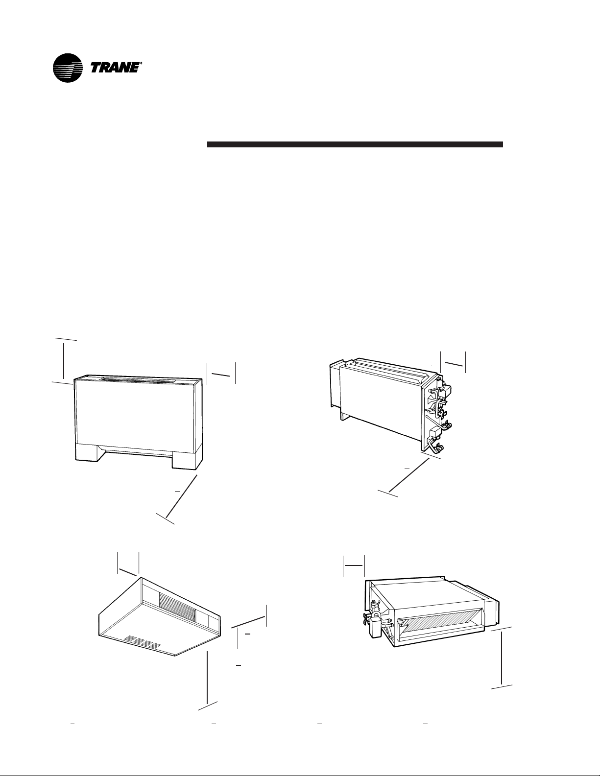
General Information
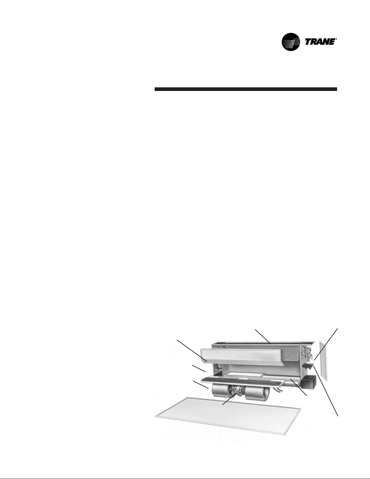
UniTrane® fan-coil and Force Flo cabinet heaters units are single
room units with load capabilities of 200 to 1200 cfm. See Figure 1
for unit components. Fan-coil units are available as 2-pipe with or
without electric heat (one hydronic circuit) or 4-pipe (two hydronic
circuits). Force Flo units feature 2-pipe hydronic coils, electric heat
only, or steam only. Also, units feature a variety of factory piping
packages. See the Appendix on page 100 for more information on
available factory-installed piping packages.
®
Three control options are available with the UniTrane
Force Flo cabinet heater units.
1. fan mode switch
®
2. Tracer
ZN.010 and ZN.510, ZN.520
3. terminal unit controller (TUC)
All control options are available as unit or wall mounted. Units with a
®
Tracer
ZN.010, ZN.510, ZN.520 or TUC also feature a split combina-
tion: unit mounted fan mode switch with a wall mounted setpoint dial.
The Tracer® controllers (ZN.010, ZN.510 and ZN.520) utilize binary
outputs to operate 2-position control valves, supply fan/s, 2-position
dampers, and electric heat.
fan-coil and
The TUC utilizes binary outputs to control the fan and optional
auxiliary heat. In addition, it operates 2-position or 3 wire floating
point control valves and the fresh air damper.
Available supply and return openings vary with each cabinet style. In
addition, a fresh air opening with either a manual or motorized air
damper is an available option. See pages 4-5 for available cabinet
styles.
Control panel
*Main drain pan
Supply fan(s)
Fan motor(s)
*Featured on fan-coils only
Figure 1. Main components of a fan-coil or cabinet heater unit.
Hydronic coil
Throwaway filter
Piping package
*Auxiliary
drain pan
UNT-IOM-6 3
Page 4
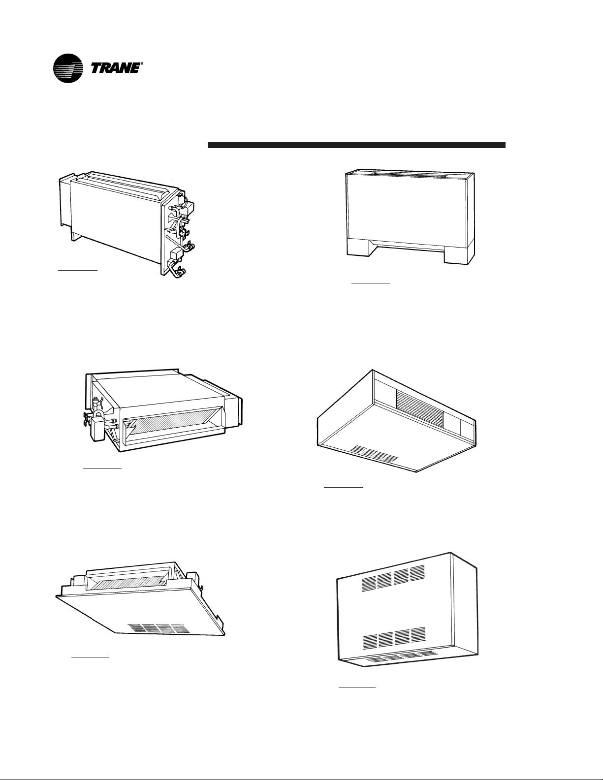
Model A
Vertical Concealed
Cabinet Styles
Model B
Vertical Cabinet
Model C
Horizontal Concealed
Model E
Horizontal Recessed
4 UNT-IOM-6
Model D
Horizontal Cabinet
Model F
Wall Hung Cabinet**
Page 5

Model H
Vertical Recessed
Model J
Vertical Slope Top Cabinet
Model K
Low Vertical Concealed*
Model M
Inverted Vertical Cabinet**
*Fan-coil only
**Force Flo cabinet heater only
Model L
Low Vertical Cabinet*
Model N
Inverted Vertical Recessed**
UNT-IOM-6 5
Page 6
Model Number
Description
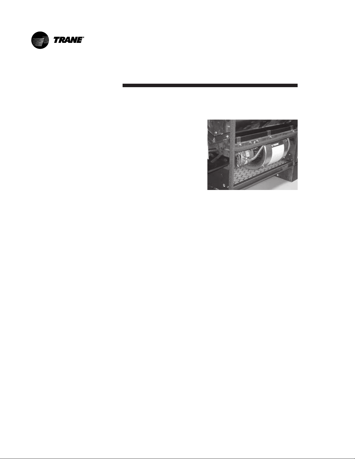
Each UniTrane® fan-coil and Force Flo cabinet heater has a
multiple character model number unique to that particular unit. To
determine a units specific
options, reference the model
number on the unit nameplate
on the fan scroll. The unit
nameplate also identifies the
serial number, sales order
number, and installation and
operating specifications. See
Figure 2 for the nameplate
location.
Reference pages 7-8 for a
detailed explanation of the
model number.
Complete the installation checklist on page 13 to ensure proper and
safe operation.
Figure 2. The unit nameplate is
on the fan scroll.
6 UNT-IOM-6
Page 7

Model Number Description
Digits 1 & 2 Unit Type
FC
FF
Digit 3 Model
A Vertical concealed
B Vertical cabinet
C Horizontal concealed
D Horizontal cabinet
E Horizontal recessed
F Vertical wall hung*
H Vertical recessed
J Vertical slope top
K Low vertical concealed
L Low vertical cabinet
M Inverted vertical cabinet*
N Inverted vertical recessed*
Digit 4 Development Sequence
B
Digits 57 Unit Size
020 200 cfm
030 300 cfm
040 400 cfm
060 600 cfm
080 800 cfm
100 1000 cfm
120 1200 cfm
Digit 8 Unit Voltage
1 115/60/1
2 208/60/1
3 277/60/1
4 230/60/1
5 208/60/3
6 230/6j0/3
7 480/60/3
8 110-120/50/1
9 220-240/50/1
A 220-240/50/3
B 380-415/50/3
Digit 9 Piping System Placement
A W/o piping, RH conn.,
w/o aux. drain pan
B W/o piping, LH conn.,
w/o aux. drain pan
C W/o piping, RH conn.,
w/ aux. drain pan
D W/o piping, LH conn.,
w/ aux. drain pan
E W/o piping, RH conn.,
w/o aux. drain pan,
ext. end pocket
F W/o piping, LH conn.,
w/o aux. drain
G W/o piping, RH conn.,
w/ aux. drain pan,
ext. end pocket
H W/o piping, LH conn.,
w/ aux. drain pan, ext. end
pocket
J With piping, RH
K With piping, LH
L With piping, RH, ext. end pocket
M With piping, RH, ext. end pocket
Digits 10 & 11 Design Sequence
LO
Digit 12 Inlet
A Front toe space
B Front bar grille
C Front stamped louver
D Bottom stamped louver
E Bottom toe space
F Back duct collar
G Open return
H Back stamped louver
Digit 13 Fresh Air Damper
0 None
A Manual, bottom opening
B Manual, back opening
C Manual, top opening
D Auto, 2 pos., bottom opening
E Auto, 2 pos., back opening
F Auto, 2 pos. top opening
G Auto, economizer,
bottom opening
H Auto, economizer, back opening
J Auto, economizer, top opening
K No damper, bottom opening
L No damper, back opening
M No damper, top opening
Digit 14 Outlet
A Front duct collar
B Front bar grille
C Front stamped louver
D Front quad grille
E Bottom duct collar
F Bottom stamped louver
G Top quad grille
H Top bar grille
J Top duct collar
K Bottom bar grille
Digit 15 Color
0 None
1 Deluxe beige
2 Soft dove
3 Cameo white
4 Driftwood grey
5 Stone grey
6 Rose mauve
Digit 16 Tamperproof Locks
& Leveling Feet
0 None
A Keylock panel
B Keylock access door
C Keylock panel & access door
D Leveling feet
E Keylock panel with leveling feet
F Keylock access door
w/leveling feet
G Keylock panel & access door
w/leveling feet
Digit 17 Motor
A Free discharge
B High static
Digit 18 Coil
A 2 row cooling/heating
B 3 row cooling/heating
C 4 row cooling/heating
D 2 row cooling, 1 row heating
E 2 row cooling, 2 row heating
F 3 row cooling, 1 row heating
G 2 row cooling or heating only
H 3 row cooling or heating only
J 4 row cooling or heating only
K 2 row cooling/heating, elec. heat
L 3 row cooling/heating, elec. heat
M 4 row cooling/heating, elec. heat
N Electric heat only, 1 stage
P 2 row cooling/heating,
1 row heating
Q 2 row cooling/heating,
2 row heating
R 3 row cooling/heating,
1 row heating
U Electric heat only, 2 stage
V Electric heat only, low kw, 1 stage
W Steam coil
Digit 19 Coil Fin Series
2 144
Digit 20 Air Vent
A Automatic
M Manual
Digits 21, 22, & 23 Electric Heat kW
[208 V kW derate in brackets]
000 None
010 1.0 [0.75]
015 1.5 [1.1]
020 2.0 [1.5]
025 2.5 [1.9]
030 3.0 [2.2]
040 4.0 [3.0]
045 4.5 [3.3]
050 5.0 [3.7]
060 6.0 [4.4]
070 7.0 [5.3]
075 7.5 [5.7]
080 8.0 [6.0]
100 10.0
105 10.5 [7.9]
110 11.0 [9.0]
120 12.0
135 13.5 [10.2]
150 15.0
180 18.0 [13.5]
200 20.0 [15.0]
*Force Flo cabinet heater only
UNT-IOM-6 7
Page 8

Digit 24 Reheat
0 None
A Steam
B Hot water
Digit 25 Disconnect Switch
0 None
D With disconnect
Digit 26 Filter
0 None
11 TA
2 1 TA pltd. media
3 1 TA + 1 extra
4 1 TA pltd. media + 1 extra
5 1 TA + 2 extra
6 1 TA pltd. media + 2 extra
7 1 TA + 3 extra
8 1 TA pltd. media + 3 extra
Digit 27 Main Control Valve
0 None
A 2 way, 2 pos., N.O. (25 psig)
B 3 way, 2 pos., N.O. (30 psig)
C 2 way, 2 pos., N.C. (25 psig)
D 3 way, 2 pos., N.C. (15 psig)
E 2 way, 2 pos., N.O. (50 psig)
F 3 way, 2 pos., N.O. (50 psig)
G 2 way, 2 pos., N.C. (50 psig)
H 3 way, 2 pos., N.C. (50 psig)
J 2 way, mod., Cv = 0.7 (50 psig)
K 3 way, mod., Cv = 0.7 (50 psig)
L 2 way, mod., Cv = 1.5 (50 psig)
M 3 way, mod., Cv = 1.5 (50 psig)
N 2 way, mod., Cv = 2.5 (50 psig)
P 3 way, mod., Cv = 2.5 (50 psig)
Q 2 way, mod., Cv = 4.0 (50 psig)
R 3 way, mod., Cv = 4.0 (50 psig)
Digit 28 Auxiliary Control Valve
0 None
A 2 way, 2 pos., N.O. (25 psig)
B 3 way, 2 pos., N.O. (30 psig)
C 2 way, 2 pos., N.C. (25 psig)
D 3 way, 2 pos., N.C. (15 psig)
E 2 way, 2 pos., N.O. (50 psig)
F 3 way, 2 pos., N.O. (50 psig)
G 2 way, 2 pos., N.C. (50 psig)
H 3 way, 2 pos., N.C. (50 psig)
J 2 way, mod., Cv = 0.7 (50 psig)
K 3 way, mod., Cv = 0.7 (50 psig)
L 2 way, mod., Cv = 1.5 (50 psig)
M 3 way, mod., Cv = 1.5 (50 psig)
N 2 way, mod., Cv = 2.5 (50 psig)
P 3 way, mod., Cv = 2.5 (50 psig)
Q 2 way, mod., Cv = 4.0 (50 psig)
R 3 way, mod., Cv = 4.0 (50 psig)
Digit 29 Piping Package
0 None
A Ball valve supply & return
B Ball valve supply & manual circuit
setter return
C Ball valve supply & auto circuit
setter
D Ball valve supply & return
w/strainers & unions
E Ball valve supply & manual circuit
setter w/strainers & unions
F Ball valve supply & auto circuit
setter w/strainers & unions
Digit 30 Control Type
A Fan Speed Switch
C TUC
D TUC w/Trane ICS
E Tracer
F Tracer
®
ZN.010
®
ZN.510
G Tracer® ZN.520
Digit 31 Control Options
D Unit mtd. fan mode switch (OHML)
K Wall mtd. fan mode switch (OHML)
V Unit mtd. zone sensor, w/SP
rotary, & fan mode switch
(OAHML),
W Wall mtd. zone sensor w/
SP rotary, & fan mode switch
(OAHML),
X Unit mtd. fan mode switch, wall
mtd. setpoint dial zone sensor
Digit 32-34 Future Control Options
Digit 35 Control Function 3
0 None
2 Condensate overflow detection
Digit 36 Control Function 4
0 None
2 Low temperature detection
Digits 37 & 38 Future Control Options
Digit 39 Recessed Options
0 None
A Stand. 5/8 recessed panel
B 2 projection panel
C 2.5 projection panel
D 3 projection panel
E 3.5 projection panel
F 4 projection panel
G 4.5 projection panel
H 5 projection panel
J 5.5 projection panel
K 6 projection panel
L 2 falseback
M 3 falseback
N 4 falseback
P 5 falseback
Q 6 falseback
R 7 falseback
T 8 falseback
Digit 40 Main Auto Circuit Setter GPM
0 None
A 0.5
B 0.75
C 1.0
D 1.5
E 2.0
F 2.5
G 3.0
H 3.5
K 4.5
L 5.0
M 6.0
N 7.0
P 8.0
Q 9.0
R 10.0
T11.0
U 12.0
J 4.0
Digit 41 Auxiliary Auto Circuit Setter GPM
0 None
A 0.5
B 0.75
C 1.0
D 1.5
E 2.0
F 2.5
G 3.0
H 3.5
K 4.5
L 5.0
M 6.0
N 7.0
P 8.0
Q 9.0
R 10.0
T11.0
U 12.0
J 4.0
Digit 42 Subbase
0 None
A 2 height
B 3 height
C 4 height
D 5 height
E 6 height
F 7 height
Digit 43 Recessed Flange
0 None
A Recessed flange
Digit 44 Wallbox
0 None
A Anodized
8 UNT-IOM-6
Page 9

Receiving and Handling
UniTrane® fan-coil and Force Flo cabinet heaters ship in individual
cartons for maximum protection during shipment and for handling and
storage ease. Each carton has tagging information such as the
model number, sales order number, serial number, unit size, piping
connections, and unit style to help properly locate the unit in the floor
plan. If specified, the unit will ship with tagging designated by the
customer.
Complete the following checklist before accepting delivery of units to
detect any shipping damage.
o 1. Inspect each piece of the shipment before accepting it.
Check for rattles, bent carton corners, or other visible indications of
shipping damage.
o 2. If the carton appears damaged, open it immediately and
inspect the contents before accepting. Do not refuse the shipment.
Make specific notations concerning the damage on the freight bill.
Check the unit casing, fan rotation, coils, condensate pan, filters, and
all options or accessories.
o 3. Inspect the unit for concealed damage and missing compo-
nents soon after delivery and before storing. Report concealed
damage to the delivering carrier within the allotted time after
delivery (check with the carrier on the allotted time to submit a
claim).
o 4. Do not move damaged material from the receiving location if
possible. It is the receivers responsibility to provide reasonable
evidence that concealed damage did not occur after delivery.
o 5. Do not continue to unpack shipment if it appears damaged.
Retain all internal packing, cartons, and crate. Take photos of the
damaged material if possible.
o 6. Notify the carriers terminal of damage immediately by phone
and mail. Request an immediate joint inspection of the damage by
the carrier and consignee.
o 7. Notify the Trane sales representative of the damage and
arrange for repair. Have the carrier inspect the damage before beginning any repairs to the unit.
UNT-IOM-6 9
Page 10

Jobsite Storage
This unit is intended for indoor use only. To protect the unit from
damage due to the elements and prevent it from possibly becoming a
contaminant source for IAQ problems, store the unit indoors. If indoor
storage is not possible, the Trane Company makes the following
provisions for outdoor storage:
1. Place the unit(s) on a dry surface or raised off the ground to assure
adequate air circulation beneath unit and to assure that no portion of
the unit contacts standing water at any time.
2. Cover the entire unit with a canvas tarp only. Do not use clear,
black or plastic tarps as they may cause excessive moisture condensation and equipment damage.
Note: Wet interior unit insulation can become an amplification site for
microbial growth (mold), which may cause odors and health-related
indoor air quality problems. If there is visable evidence of microbial
growth (mold) on the interior insulation, remove and replace the
insulation prior to operating the system. Refer to the Inspecting and
Cleaning the Internal Insulation section on page 123 for more
information.
10 UNT-IOM-6
Page 11

Installation
Considerations
Complete the following checklist before installing the unit.
o 1. Clearances
Allow adequate space for free air circulation, service clearances,
piping and electrical connections, and any necessary ductwork. For
specific unit dimensions, refer to the submittals. Allow clearances
according to local and national electric codes. See the following
section on Service Access and refer to Figure 3 on page 12 for
recommended service and operating clearances. Provide removable
panels for concealed units.
o 2. Structural Support
The floor should be strong enough to adequately support floor
mounted units. The installer is responsible to supply adequate
support rods for installation of ceiling units.
o 3. Level
If necessary, prepare the floor or ceiling to ensure the unit installation
is level (zero tolerance) in both horizontal axis to allow proper
operation.
Set the unit level using the chassis end panels as a reference point.
Do not use the coil or drain pan as the reference point since the coil
is pitched and the drain pan has an inherent positive slope to provide
proper drainage.
o 4. Condensate Line
A continuous pitch of 1 inch per 10 feet of condensate line run is
necessary for adequate condensate drainage.
o 5. Wall and Ceiling Openings
Recessed units only:
Refer to the submittal for specific dimensions of wall or ceiling
openings before attempting to install the unit.
Horizontal concealed units only:
The installation of horizontal concealed units must meet the requirements of the National Fire Protection Association (N.F.P.A.) Standard 90A or 90B concerning the use of concealed ceiling spaces as
return air plenums.
o 6. Exterior
Touch up painted panels if necessary. If panels need paint, sanding
is not necessary. However, clean the surface of any oil, grease, or
dirt residue so the paint will adhere. Purchase factory approved touch
up epoxy paint from your local Trane Service Parts Center and apply.
UNT-IOM-6 11
Page 12
Service
Access
24 in.
Vertical or Low
Vertical Cabinet
A
Service access is available from the front on vertical units and from
the bottom on horizontal units. Cabinet and recessed units have
removable front or bottom panels to allow access into the unit. See
Figure 3 for recommended service and operating clearances.
Units have either right or left hand piping. Reference piping locations
by facing the front of the unit (airflow discharges from the front). The
control panel is always on the end opposite the piping.
The unit has a modular fan board assembly that is easy to remove.
Also, the main drain pan is easily removable for cleaning. See the
Maintenance section beginning on page 88 for more details on
servicing.
8.5 in.
12 in.
both sides
both sides
Vertical or Low Vertical
Concealed or Vertical
Recessed
3 in.
A
36 in.
12 in.
both sides
24 in.
C
28 in.
6 in.
B
Horizontal
Cabinet
A- Front Access or Front Free Discharge B- Control Access Door C- Front Free Discharge D- Back Louvered Return
Figure 3. Recommended Service and Operating Clearances
12 UNT-IOM-6
8.5 in.
both sides
Horizontal Concealed
or Recessed
28 in.
Page 13

Installation Checklist
The following checklist is only an abbreviated guide to the detailed
installation procedures given in this manual. Use this list to ensure all
necessary procedures are complete. For more detailed information,
refer to the appropriate sections in this manual.
WARNING: Allow rotating fan to stop before
!
servicing equipment. Failure to do so may cause severe
personal injury or death.
o 1. Inspect the unit for shipping damage.
o 2. Level installation location to support the unit weight ad-
equately. Make all necessary wall or ceiling openings to allow
adequate air flow and service clearances.
o 3. Ensure the unit chassis is level.
CAUTION: The unit must be installed level (zero
!
tolerance) in both horizontal axis for proper operation.
Failure to do so may result in condensate management
problems such as standing water inside the unit. Standing water and wet surfaces may result in microbial
growth (mold) in the drain pan that may cause unpleasnt
odors and serious health-related indoor air quality problems.
o 4. Secure the unit and any accessory items properly to the
wall or ceiling support rods.
o 5. Complete piping connections correctly.
o 6. Check field sweat connections for leaks and tighten the
valve stem packing, if necessary.
o 7. Install the auxiliary drain pan properly under piping package
on fan-coil units.
o 8. Pitch condensate drain line 1 inch drop per 10 feet of line
run on fan-coil units.
UNT-IOM-6 13
Page 14

o 9. Complete condensate drain line connections on fan-coil
units.
o 10. Install automatic changeover sensor option on the
supply water line.
o 11. Install automatic electric heat lockout switch option on
the supply water line.
o 12. Install condensate overflow switch option correctly on
the auxiliary drain pan.
o 13. Install the low temperature detection device option correctly.
o 14. Complete all necessary duct connections.
o 15. Complete all interconnection wiring for the wall mounted fan
mode switch or zone sensor per the wiring schematic and guidelines
established in the Wall Mounted Control Interconnection Wiring
section on page 35.
o 16. Install the wall mounted fan mode switch, or zone sensor
module options properly.
o 17. Connect electrical supply power according to the NEC and
unit wiring diagrams.
o 19. Remove any miscellaneous debris, such as sheetrock, that
may have infiltrated the unit during construction.
o 20. Replace the air filter as required.
14 UNT-IOM-6
Page 15
Installing the Unit
Before beginning installation, refer to Table 1 on page 17 for unit
weights and Figure 3 on page 12 for service and operating clearances.
In addition, refer to the unit submittal for installation details.
CAUTION: Do not allow electrical wire to fall
!
between the unit and installation surface. Failure to
comply may cause electrical shorts or difficulty in accessing wires.
Vertical Units
Cabinet & Concealed Units
Size L (in.)
02 21 1/4
03 21 1/4
04 26 1/4
06 35 3/4
08 44 1/4
10 63 1/4
12 63 1/4
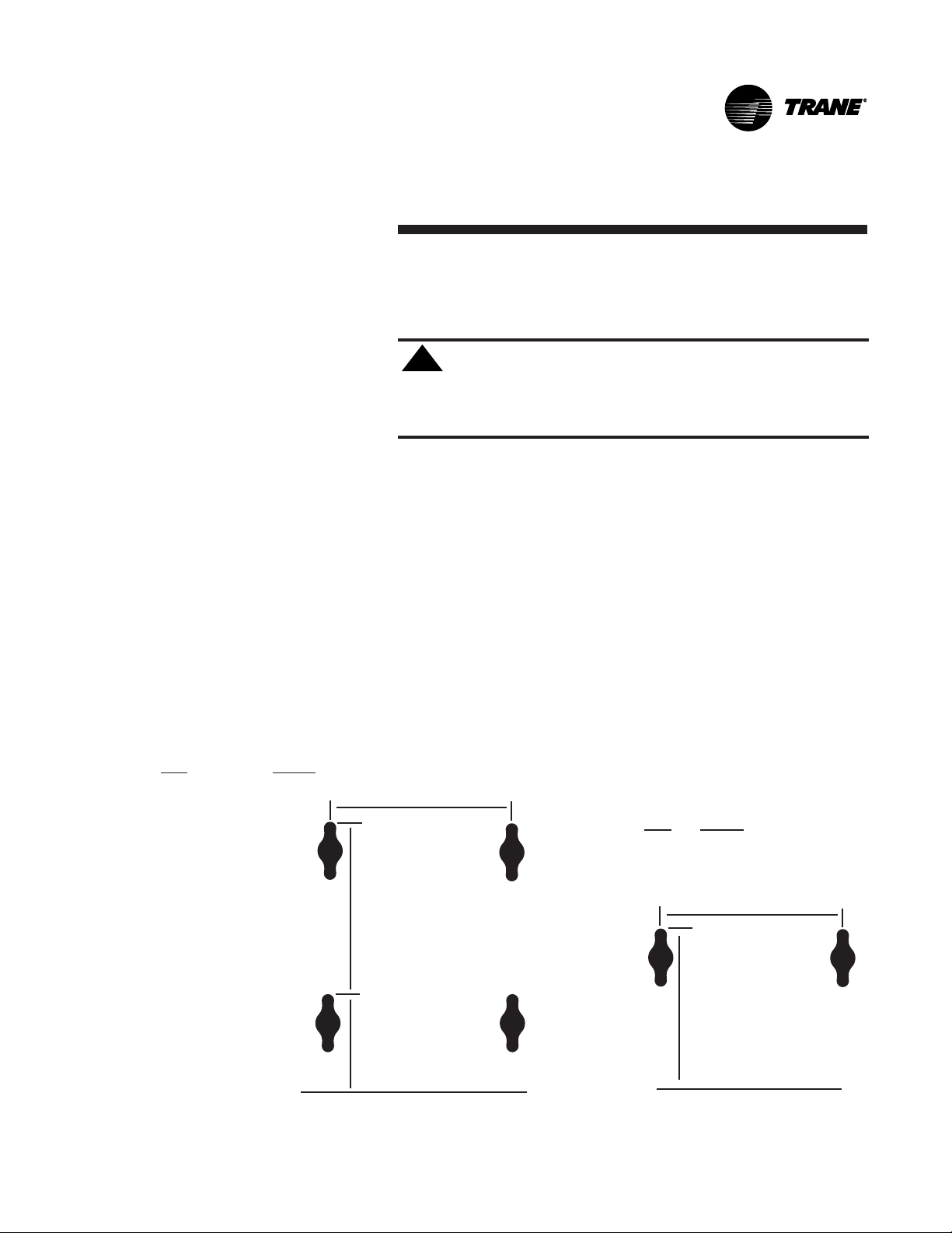
Install vertical units in an upright position using the 5/8 inch diameter
double key slot hanger holes, located on the back of unit. The hanger
holes allow a maximum shank size of 5/16 inch diameter threaded
rods or lag screws (installer provides). Follow the installation procedure below.
1. Prepare wall openings for recessed units. Reference unit submittal
for each unit size dimensions.
2. If the unit has leveling legs, adjust them correctly to level unit.
3. Mark the position of the keyslot hanger holes on the wall according
to the dimensions given in Figure 4 for each unit size. Align the
hole locations evenly.
L
15.5 in.
Low Vertical Cabinet & Concealed
Size L (in.)
03 26 1/4
04 35 3/4
06 44 1/4
L
12.19 in.
7.5 in.
Floor Level
Figure 4. Keyslot Hanger Hole Locations
UNT-IOM-6 15
Floor Level
Page 16

4. Insert the threaded rods or lag screws in the wall before setting the
unit in place.
5. Remove the front panel (cabinet unit only) by lifting it upward.
6. Position the hanger holes, located on the back of the unit, over the
rod or lag screw heads, pushing the unit downward to properly
position.
7. Complete piping and wiring connections, in addition to any necessary ductwork to the unit as instructed in the following sections.
Ensure that the auxiliary drain pan is in position on fan-coil units.
8. Install the front panel before starting the unit.
On cabinet units, replace the front panel by aligning the bottom tabs
on the unit with the respective slots on the panel bottom. Align the
top edge of the unit with the panel.
On recessed units, install the front panel by aligning and locking
together the interlocking support channel of the panel and unit. While
holding the panel against the unit, tighten the screws at the top of the
panel until it fits tight against the units front. Do not over tighten the
screws.
CAUTION: All unit panels and filters must be in
!
place prior to unit start-up. Failure to have panels and
filters in place may cause motor overload.
Horizontal Units
16 UNT-IOM-6
Install horizontal units suspended from the ceiling using the four 5/8
inch diameter double key slot hanger holes, located on the top of the
unit. The hanger holes allow a maximum shank size of 5/16 inch
diameter threaded rods or lag screws (installer provided). Follow the
installation procedure below.
Note: Follow the requirements of National Fire Protection Association
(NFPA) Standard 90A or 90B, concerning the use of concealed
ceiling spaces as return air plenums.
1. Prepare the ceiling opening for recessed units. Reference the unit
submittals for each unit size dimensions.
Page 17

2. Position and install the suspension rods or a suspension device
(supplied by installer) according to the unit size dimensions in
Figure 4 on page 15. Also refer to the weight range chart given in
Table 1.
3. On cabinet units, remove the bottom panel by using a 5/32 inch
Allen wrench to unscrew fasteners. Swing the panel down and lift
outward.
4. Level the unit by referencing the chassis end panels. Adjust the
suspension device.
5. Complete piping and wiring connections, in addition to any neces
sary ductwork as instructed in the following sections. Ensure that
the auxiliary drain pan is in position on fan-coil units.
6. Install the bottom panel before starting the unit.
7. Ensure condensate drain line is pitched 1 inch per 10 feet of pipe
away from fan-coil unit.
Table 1. Unit Operating Weights, pounds (kg)
Unit Cabinet Concealed Recessed Low Vertical Low Vertical
Size Models Models Models Cabinet Models Concealed
Models
02 84 (38) 68 (31) 68 (31) NA NA
03 84 (38) 68 (31) 68 (31) 112 (51) 96 (44)
04 112 (51) 96 (44) 78 (35) 139 (63) 123 (56)
06 139 (63) 123 (56) 118 (54) 148 (67) 131 (59)
08 148 (67) 131 (59) 129 (59) NA NA
10 200 (91) 182 (83) 243 (110) NA NA
12 200 (91) 182 (83) 243 (110) NA NA
Note: All weights are approximate. Individual weights may vary depending upon the units options.
UNT-IOM-6 17
Page 18

Cabinet units:
Install the bottom panel by placing the hinged end on the units hinged
end (always at the return end of the unit). See Figure 4 on page 15 for
keyslot hanger hole locations. Swing the panel upward into position.
Tighten the panel to the unit with the fasteners provided. Do not overtighten the fasteners.
Recessed units:
See Figure 5 on page 19 and follow the procedure below.
· Insert the mounting bolts through the panel brackets of the trim ring
and secure to the hanger holes on the unit. Tighten the mounting
bolts to pull the trim ring snug against the finished ceiling.
· Install the bottom panel by placing the hinged end on the trim ring
hinged end (always at the units return end).
· Adjust the inner duct of the expansion collar (on units with a bottom
return) to ensure a tight fit against the insulation located on the
perimeter of the bottom panels return louver.
· Safety chain assembly: close s-hook on each end of chain. Insert s hooks through holes in unit and door. Close s-hook on door.
· Insert retaining screws through bottom panel door and place
retaining rings on screws.
· Swing the bottom panel upward into position. Hook the safety chain
to the bottom panel and the unit. Tighten the panel to the unit with
the fasteners provided. Do not over tighten the removable front
access panel.
CAUTION: All unit panels and filters must be in
!
place prior to unit start-up. Failure to have panels and
filters in place may cause motor overload.
Note: The trim ring assembly cannot accomodate unlevel ceilings.
18 UNT-IOM-6
Page 19

Figure 5. Trim ring assembly installation.
UNT-IOM-6 19
Page 20

Startup Checklist
o 1. Ensure all panels are in place.
o 2. Tighten unions adequately if unit has a factory deluxe piping
package.
o 3. Properly vent the hydronic coil to allow water flow through the
unit.
o 4. Set water flow to the unit properly if unit piping has the circuit
setter valve.
o 5. Check strainers (if supplied) for debris after applying system
water.
o 6. Install the auxiliary drain pan and route the main drain pan
hoses to the auxiliary drain pan on vertical fan-coil units.
o 7. Ensure all grille options are in place.
External Insulating
Requirements
o 8. Ensure the air filter is in place.
o 9. Set the damper position to allow the fresh air requirement on
units with a fresh air damper.
Note: Some circumstances may require the unit to run before building
construction is complete. These operating conditions may be beyond
the design parameters of the unit and may adversely affect the unit.
Insulate all cold surfaces to prevent condensation. Moisture mixed
with accumulated dirt and organic matter may create an amplification
site for microbial growth (mold) causing unpleasant odors and healthrelated indoor air quality (IAQ) problems.
The Trane Company recommends field-insulation of the following
areas to prevent potential condensate and IAQ problems:
1. Supply and return water piping connections
2. Condensate drain lines and connections
3. Fresh air intake duct connections
4. Discharge duct connections
5. Wall boxes
20 UNT-IOM-6
Page 21
Piping
Units with
Hydronic Coil
Connections Only
Piping Considerations
Before installing field piping to the coil, consider the following .
· All coil connections are 5/8 inch O.D. (or 1/2 inch nominal) female
copper connections.
· The supply and return piping should not interfere with the auxiliary
drain pan or condensate line. See Connecting the Condensate
Drain section on page 25 for more detailed information.
· The installer must provide adequate piping system filtration and
water treatment.
· Condensate may be an issue (fan-coils only) if field piping does not
have a control valve.
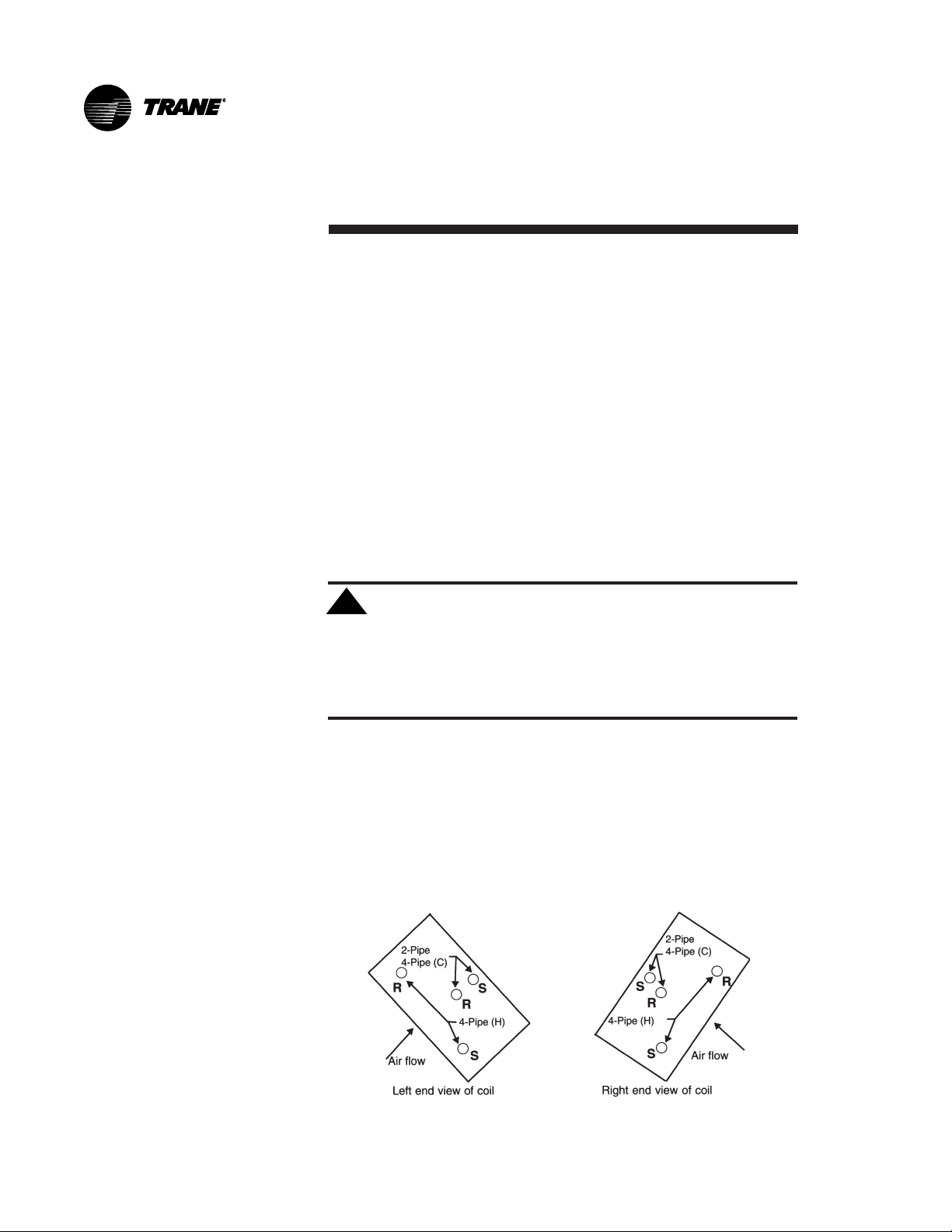
Refer to Figure 6 for supply and return header locations.
CAUTION: When using a field supplied piping
!
package in a fan-coil unit, allow sufficient room to install
the auxiliary drain pan. In addition, piping package must
not extend over edges of auxiliary drain pan.
S
R
S
2-Pipe
4-Pipe (C)
R
Air flow
2-Pipe
4-Pipe (C)
R
Air flow
Left end view of coil
Figure 6. Supply and return header locations on the hydronic
coil.
Connecting field piping to coil:
1. Slide a 1/2 inch sweat connection coupling (installer provided) onto
the coil headers.
2. Remove the auxiliary drain pan, if it is in place, to prevent exposure
to dripping solder or excessive temperatures.
UNT-IOM-6 21
S
R
4-Pipe (H)
S
4-Pipe (H)
Right end view of coil
Page 22
Units with Steam
Coils
Note: For vertical fan-coil units, push the main condensate drain
hose and overflow condensate drain hose through to the inside of the
chassis end panel to prevent them from being burned when making
sweat connections. Be sure to pull the hoses back through and route
to the auxiliary drain pan when the end panel has cooled.
3. Solder the joint using bridgit lead-free solder (ASTM B32-89) to
provide a watertight connection. Avoid overheating factory soldered
joints when soldering field connections to the coil to prevent
leakage from occurring.
4. Insulate all piping to coil connections as necessary after connections are complete.
Note: Maintain a minimum distance of one foot between the reduction
fitting for the 1/2 inch diameter line and the fan-coil unit piping
connections.
Install the auxiliary drain pan, which ships in the accessory packet
CAUTION: In all steam coil installations, the con-
!
densate return connections must be at the low point of
the coil to ensure condensate flows freely from the coil
at all times. Failure to do so may cause physical coil
damage from water hammer, unequal thermal stresses,
freeze-up and/or corrosion.
1. Make piping connections to the steam coil as shown in Figure 7.
Cap the unused connection.
2. The coil is already pitched within the unit to provide proper pitch to
drain condensate out of the coil. Ensure that the unit has been
properly leveled. Refer to page 13 for unit leveling instructions.
3. Install a 1/2 inch, 15-degree swing check vacuum breaker in the
unused condensate return tapping as close as possible to the coil.
Figure 7. Steam coil header ports. The center port is the supply
connection. The return port is below the supply. The top port
must be closed off.
22 UNT-IOM-6
Page 23
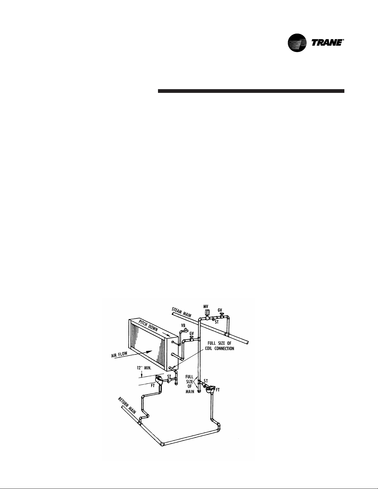
4. Vent the vacuum breaker line to atmosphere or connect it into the
return main at the discharge side of the steam trap.
5. Pitch all steam supply and return mains down a minimum of 1 inch
per 10 feet in the direction of flow.
6. Do not drain the steam mains or take-off through the coils. Drain
the mains ahead of the coils through a steam trap to the return line.
7. Overhead returns require 1 psig of pressure at the steam trap
discharge for each 2-foot elevation to ensure continuous condensate
removal.
8. Proper steam trap selection and installation is necessary for
satisfactory coil performance and service life. For installation, use the
following steps:
a. Locate the steam trap discharge at least 12 inches below the
condensate return connection. This provides sufficient hydrostatic
head pressure to overcome trap losses and ensure complete condensate removal.
b. Trane Company recommends using flat and thermostatic traps
because of gravity drain and continuous discharge operation.
c. Use float and thermostatic
traps with atmospheric pressure
gravity condensate return, with
automatic controls or where the
ST = Strainer
FT = Float and
thermostatic
steam trap
MV = Manual
air vent
GV= Gate valve
VB = Vacuum
breaker, 15°
swing check
valve
possibility of low pressure supply
steam exists.
d. Always install strainers as
close as possible to the trap inlet
side.
Reference Figure 8 for an example of a properly piped steam
coil.
Figure 8. Example of typical piping to the steam coil.
UNT-IOM-6 23
Page 24

Factory Piping
Package
Connections
Before installing water piping supply and return lines to factory
piping package, note the following items.
· All piping connections are 5/8 inch O.D. (1/2 inch nominal) female
copper connections.
Piping Considerations
Connecting Water Piping to
Factory Piping Package
· The fan-coil supply and return piping should not interfere with the
auxiliary drain pan or condensate line. See Connecting the
Condensate Drain section on page 25 for more information.
· The installer must provide adequate piping system filtration and
water treatment.
· If the unit has a factory deluxe piping package, the piping includes
a strainer with a 20 mesh size screen, which allows minimal
protection from debris. Therefore, clean the strainer regularly.
NOTE: Maintain a minimum distance of one foot between the
reduction fitting for the 1/2 inch diameter line and the fan-coil piping
connections.
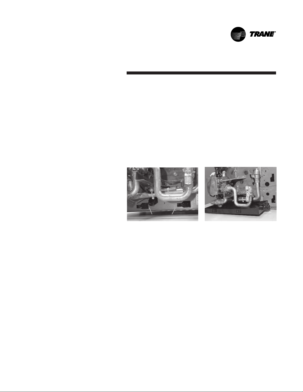
1. The factory piping package ships with brackets to adequately
support the piping during shipment. Remove these brackets before
connecting water piping to the unit. See Figure 9.
2. Close the piping end valves to the fully open position to prevent
damage to the valve seat during brazing.
3. Remove the auxiliary drain pan, if it is in place, to prevent exposure to dripping solder or excessive temperatures.
4. Solder water piping connections to supply and return end
connections. Avoid overheating
factory soldered joints to
prevent the possibility of
leakage.
5. Insulate fan-coil piping to
auxiliary drain pan connections
and any piping that is not above
the auxiliary drain pan.
Figure 9. Remove the shipping
brackets which support the
factory piping package before
connecting piping.
24 UNT-IOM-6
Page 25
Installing the
Auxiliary Drain
Pan
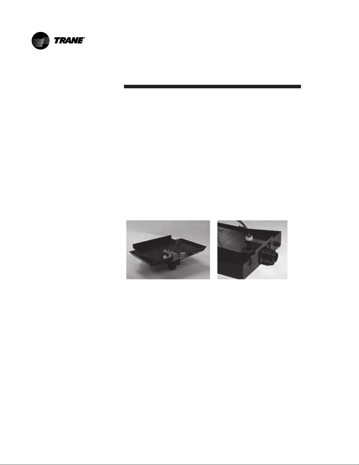
The auxiliary drain pan ships loose with a fan-coil unit with factory
piping. To install the auxiliary drain pan, insert the tabs, located on
the side of the drain pan, into the slots located in the chassis end
panel. Slide the pan into the narrow groove section to lock into place.
See Figures 10 and 11. Make sure the auxiliary pan is pushed all the
way into the fully locked position.
Note: The function of the auxiliary drain pan is to collect condensate
from the main drain pan and the factory installed piping package only.
It also provides a convenient field connection for the condensate
drain line for units without factory piping. Moreover, the auxiliary drain
pan may not be adequate to collect condensate from a field-installed
piping package. Apply additional insulation as needed.
Connecting the
Condensate Drain
Figure 10. Insert the auxiliary
drain pan tabs into these slots
in the fan-coil chassis end
panel.
1. De-burr the pipe end before making the connection to the drain pan.
2. Connect a 7/8 inch O.D. copper pipe or tube, with a 0.20 inch wall
thickness, to the auxiliary drain pan. This should be a mechanical
connection that allows easy removal of the auxiliary drain pan when
servicing the piping end pocket.
3. Slide the copper pipe over the drain pan nipple and tighten the
collar on the pipe with a hose clamp (installer supplied).
Maintain a continuous drain line pitch of 1 inch per 10 feet of drain line
run to provide adequate condensate drainage. Extend the drain line
straight from the drain pan a minimum distance of 6 inches before
making any turns. The installer must provide proper support for the
drain line to prevent undue stress on the auxiliary drain pan.
Install a secondary overflow drain line if necessary by punching out
the overflow drain nipple on the auxiliary drain pan. Next, place a 3/8
Figure 11. The horizontal
auxiliary drain pan in its
installed position.
UNT-IOM-6 25
Page 26
inch inside diameter flexible plastic tube over the nipple and secure
with a field supplied hose clamp.
Note: The installer is responsible for adequately insulating field
piping. See the External Insulating Requirements section on page 20
for more information.
Condensate
Overflow
Detection Device
Automatic
Changeover
Sensor
The condensate overflow detection device is an option on fan-coil
units with either a Tracer
The float switch, mounting bracket, and coiled leads ship attached
inside the piping end pocket of the unit. Install the switch by placing
the hole or slot in the bracket over the condensate overflow drain (of
the auxiliary drain pan) with the switch float extending over the pan.
Secure the drain pan by attaching the pans bracket with the factory
provided clip. See Figures 12 and 13.
Figure 12. Condensate
overflow switch installed in a
vertical auxiliary drain pan.
Two-pipe changeover units with either the Tracer
ZN.520 or TUC control have an automatic changeover sensor that
determines heating or cooling mode based on the supply water
temperature. On units with a factory piping package, the factory
straps the changeover sensor to the piping supply water pipe. See
Figure 14 on page 27.
®
ZN.010, ZN.510, ZN.520 or TUC control.
Figure 13. Condensate
overflow switch installed in a
horizontal auxiliary drain pan.
®
ZN.010, ZN.510,
If the unit does not have a factory piping package, the factory attaches the sensor and coiled lead wires to the piping side end panel.
The installer should attach the sensor parallel to and in direct contact
with the supply water pipe.
Note: The installer is responsible to ensure the changeover sensor is
installed in a location that can sense active water temperature.
Otherwise, the unit may fail to sense the correct operating mode and
disable temperature control.
26 UNT-IOM-6
Page 27

When using field supplied 3-way valves, position the changeover
sensor upstream of the valve on the supply water pipe.
Recommendation: When using field supplied 2-way control
valves, attach the changeover sensor in a location that will
detect an active water temperature. The unit must always be
able to sense the correct
system water temperature,
regardless of the control valve
position.
Note: The maximum length of
the automatic changeover wire
cannot exceed 10 feet from the
control panel. If the sensor
extends beyond the unit chassis,
use shielded conductors to
eliminate radio frequency
interference (RFI).
Figure 14. The changeover
sensor strapped to the supply
water pipe.
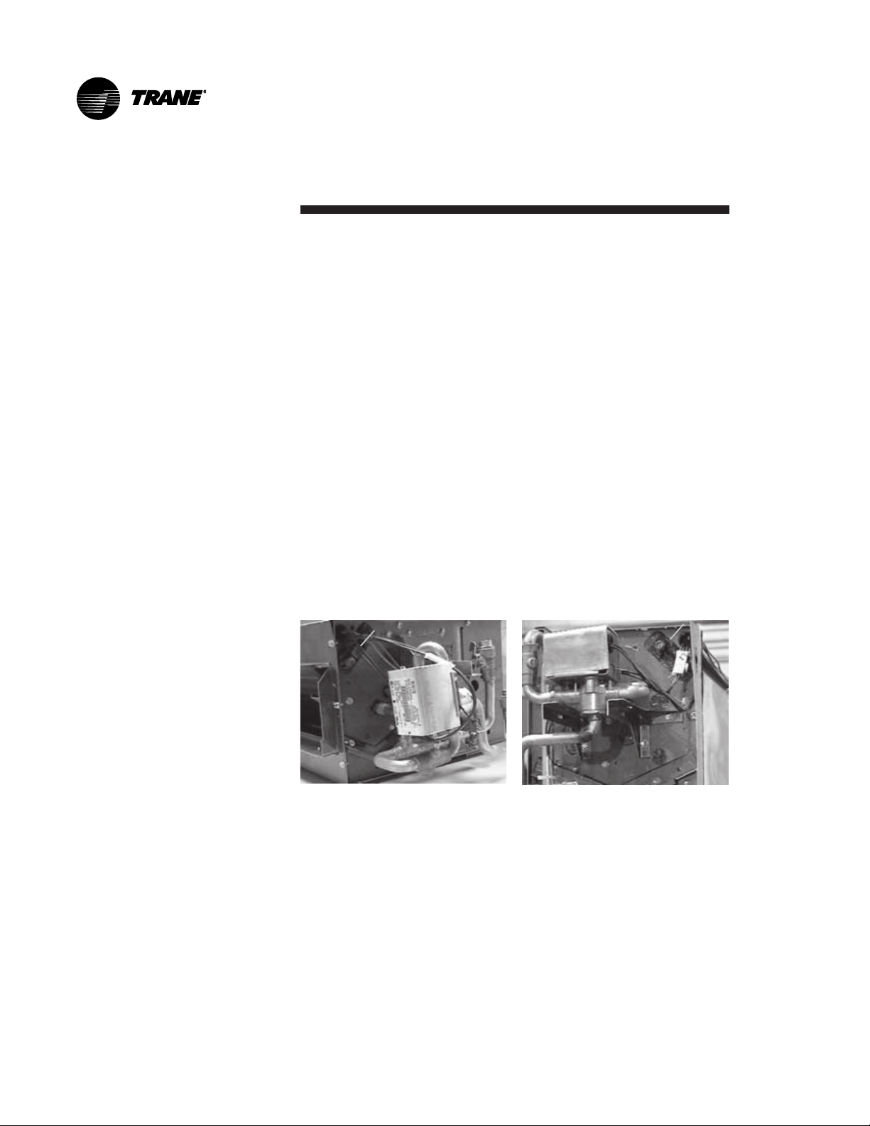
Automatic Electric
Heat Lockout
Switch (Fan-coil)
Two-pipe fan-coil units with auxiliary electric heat have an automatic
electric heat lockout switch that disengages the electric heat when
hydronic heat enables. If the unit has a factory piping package and
electric heat, the factory attaches the switch to the supply water
pipe. When the lockout switch detects the supply water temperature
above 95° F, it disengages the
electric heat. This eliminates
electric heat and hydronic heat
working simultaneously.
If the fan-coil unit does not have
a factory piping package, the
factory attaches the switch and
coiled lead wires to the piping
side end panel. The installer
should position the lockout
switch on the supply water line of
the unit by sliding its spring
connector over the pipe.
See Figure 15.
Figure 15. Units with electric
heat have an electric heat
lockout switch on the supply
water pipe.
UNT-IOM-6 27
Page 28
Venting the Hydronic
Coil
The hydronic coil contains a vent, either manual or automatic, to
release air from the unit. This vent is not sufficient for venting the
water piping system in the building.
Locate the coil air vent on the piping side, above the coil connections
on the unit. Perform the following steps to vent the coil after installing
the unit. See Figure 16.
1. Pressurize the building piping system with water and vent any
trapped air at system vents.
2. For units with manual air vents, back the set screw out to expel air
from the unit and then re-tighten the set screw.
The automatic air vent should require no adjustment for the coil to
vent. However, if the coil does not vent immediately, unscrew the outer
portion of the fitting to expel air from the port.
If debris has become trapped in the vent, completely remove the outer
portion of the fitting and clean.
Figure 16. The hydronic coil air vent is above the coil
connections. A horizontal unit is on the left and a vertical on
the right.
28 UNT-IOM-6
Page 29

Balancing The Manual
Circuit Setter Valve
The manual circuit setter valve is an optional end valve supplied on
the return pipe of the factory piping package. The valve allows the
operator to regulate water flow through the hydronic coil, balance the
water flow through the unit with other units in the piping system, and
serves as a shutoff or end valve. See Figure 17.
Follow the procedure below to set maximum water flow through the
coil.
1. Establish water flow through the coil. Perform an open override of
the valve if the control valve is closed to the coil, either manually or
®
by Tracer
.
If the piping package has 2-position, normally closed valves:
Drive open the valve using a 24V signal.
If the piping package has 2position, normally open
valves:
Manually drive open the valve by
removing power to the valve.
If the piping package has
modulating valves:
To manually drive the valve open,
depress the button stem on top
of the valve and push the lever
located on the side of the valve to
Figure 17. Manual circuit setter
valve.
the full open position.
2. For presetting, use the appropriate valve curve shown in Figure 19
on page 30 to determine which setting is necessary to achieve the
appropriate pressure drop.
3. Carefully remove the Schrader pressure port connection caps on
the manual circuit setter, since they will be at the same temperature
as the pipeline.
4. Bleed all air from the hoses and meter before reading the pressure
drop. Refer to the gauge operating instructions.
5. Adjust the circuit setter valve by turning the valve stem until the
appropriate pressure drop is achieved. See Figure 18 on page 30.
6. After achieving the proper setting, slightly loosen the two socket
head cap screws and rotate the memory stop around until it
touches the back side of the indicator. Then tighten the screws to
UNT-IOM-6 29
Page 30

securely set the open memory position. The memory stop indicates
the last set open position.
7. If using a 3-way valve: close the control valve to the coil, with the
differential pressure meter still
connected. This will divert flow to
the bypass side of a 3-way valve.
Adjust the balancing fitting to
obtain the same pressure drop
across the circuit setter valve as
in step 2 when the control valve
was open to the coil.
Figure 18. Close-up view of
manual circuit setter valve.
Figure 19. Setting the manual circuit setter valve, differential
pressure vs. flow.
30 UNT-IOM-6
Page 31

Balancing The Automatic Circuit Setter
Valve
The automatic flow valve is an
optional end valve on the return of
the factory piping package.
See Figure 20. The valve regulates water flow through the coil
to a specific (gpm) flow rate, as
ordered by the customer.
The automatic flow valve controls
to the specified flow rate, provided that the pressure drop
across the valve is within a
certain range. To verify that the
valve is operating properly, remove the protective caps from the P/T
ports and measure the pressure drop across the valve with a differential pressure meter. Carefully remove the P/T port connection caps,
since they will be at the same temperature as the pipeline. The
reading should be within the given ranges in Table 2. If the pressure
drop is not within the ranges listed, the valve will not control water
flow. If the valve orifice becomes clogged with debris, remove water
from piping and then remove the cap of the valve body and push on
the piston to dislodge any foreign matter. If this is not successful,
remove the cartridge and clean.
Figure 20. Automatic circuit
setter valve.
Table 2. Automatic Circuit Setter Flow Rate Range.
Valve gpm Pressure Drop Range (psig)
0.5 to 8.0 2 to 32
9 to 12 5 to 50
Replace the cartridge in the field without breaking the piping line to
furnish a higher or lower gpm. To do this, remove the water from the
system. Remove the cap assembly containing the plug from the valve
body. Grasp the cartridge by the piston to remove. Install a different
spring if the pressure drop range of the valve is being changed also.
UNT-IOM-6 31
Page 32

Duct Connections
The units airflow configuration varies dependent on the model and
options ordered. A one-inch duct collar is provided on units with a
ducted return and/or discharge to attach ductwork to the unit.
The Trane Company recommends using galvanized sheet metal
ductwork with fan-coil and cabinet heater units. Slide the sheetmetal
duct over the duct collar flange of the unit, seal the joint and fasten
with sheetmetal screws.
Note: Do not run screws through the removable front panel on concealed units.
Install all air ducts according to National Fire Protection Association
standards for the Installation of Air Conditioning and Ventilating
Systems (NFPA 90A and 90B).
Ductwork
Recommendations
Follow the general recommendations listed below when installing
ductwork for the unit.
· Discharge ductwork should run in a straight line, unchanged in size
or direction, for a minimum equivalent distance of 3 fan diameters
from the unit (approximately 20 inches).
· When making duct turns and transitions avoid sharp turns and use
proportional splits, turning vanes, and air scoops when necessary.
· When possible, construct, and orient supply ductwork turns in the
same direction as the fan rotation.
32 UNT-IOM-6
Page 33

Electrical Connections
Supply Power
Wiring
Refer to the unit nameplate to obtain the minimum circuit ampacity
(MCA) and maximum fuse size (MFS) or maximum circuit breaker
(MCB) to properly size field supply wiring and fuses or circuit breakers. See Figure 2 on page 6 to reference the nameplate location.
Refer to the unit operating voltage listed on the unit wiring schematic,
submittal, or nameplate. Reference the wiring schematic for specific
wiring connections.
WARNING: Hazardous voltage! Disconnect all
!
electric power including remote disconnects before
servicing. Failure to do so may cause severe personal
injury or death.
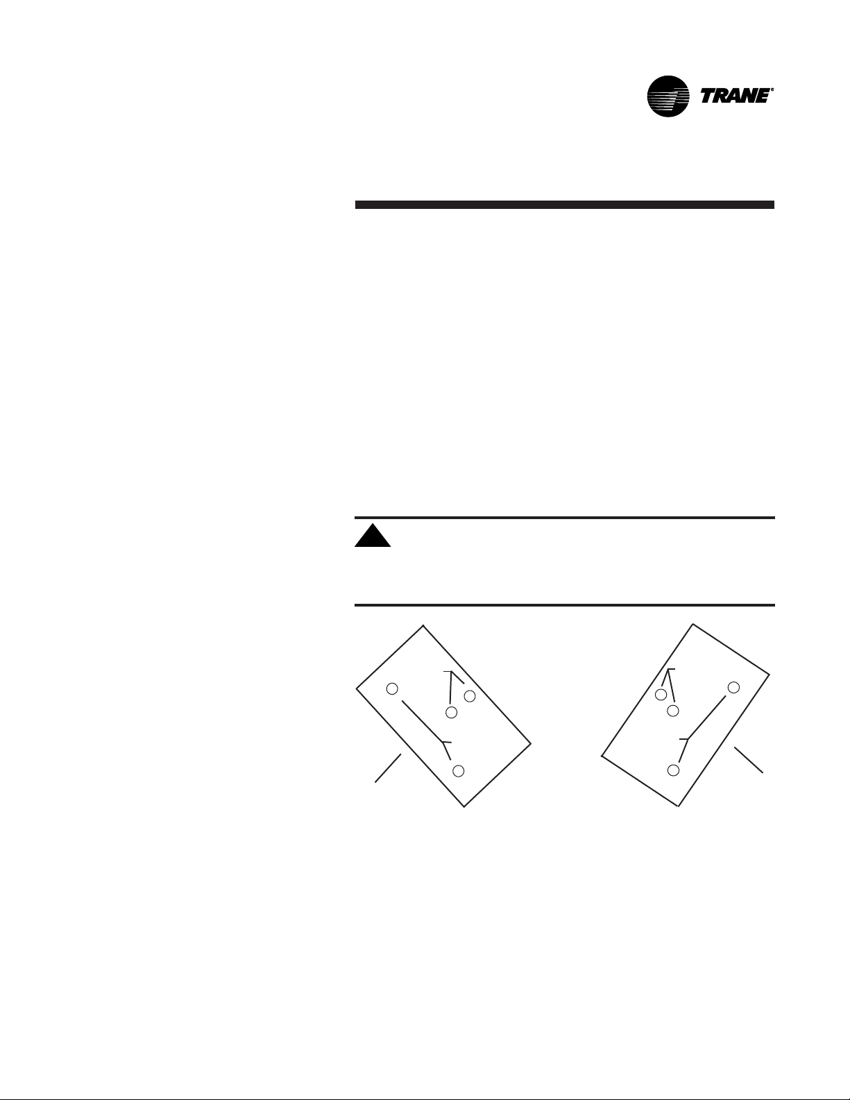
Wiring diagrams are attached to the unit in a plastic bag and can be
be easily removed for reference. Wiring schematics are attached as
follows:
· Vertical cabinet & recessed units:
Schematics are on the inside of the front panel. See Figure 21.
· Vertical concealed & all horizontal units:
Locate schematics on the fan and motor panel of unit. See Figure 22.
CAUTION: Use copper conductors only! Unit
!
terminals are not designed to accept other types of
conductors. Failure to do so may cause damage to the
equipment.
Figure 21. Locate the wiring
schematic on the inside of the
front panel of vertical cabinet
and recessed units.
Figure 22. Locate the wiring
schematic on the fan and
motor panel of vertical
concealed and all horizontal
units. (This unit is turned on
it's side.)
UNT-IOM-6 33
Page 34

All field wiring should conform
to NEC and all applicable
state and local code requirements.
The control panel box is
always on the end opposite
the piping connections.
Access the control box by
removing the two screws that
secure the front cover. If the
unit has a terminal unit control
board (TUC), remove the screw
in the top right corner of the
panel. This will allow the panel
to pivot downward to provide
access to the electrical
components. See Figure 23.
WARNING: Insulate all power wire from sheetmetal
!
Figure 23. The terminal unit
control (TUC) board pivots
downward to provide service
access.
ground. Failure to do so may cause electrical shorts
resulting in personal injury or death.
Units have one of three different connection points, depending on the
unit type and options.
1. Power & ground inside of control box:
®
If the unit has a fan mode switch, Tracer
ZN.010 or ZN.510 control
without a disconnect switch, the power leads and capped ground
wire are inside the control panel.
2. Power & ground inside the junction box:
If the unit has a TUC control without a disconnect switch, the power
leads and capped ground wire are inside the junction box on the
control panel.
3. Power wired to switch on junction box & ground inside of junction
box:
If the unit has a disconnect switch, the power leads wire to the
junction box switch on the control panel. Pull the capped
ground wire into the junction box.
34 UNT-IOM-6
Page 35

Electrical
Grounding
Restrictions
All sensor and input circuits are normally at or near ground (common)
potential. When wiring sensors and other input devices to the Tracer
ZN.010, ZN.510, ZN.520 or TUC, avoid creating ground loops with
grounded conductors external to the unit control circuit. Ground loops
can affect the measurement accuracy of the controller.
CAUTION: Unit transformer IT1 provides power to
!
fan-coil unit only. Field connections to the transformer
IT1 may create immediate or premature unit component
failure.
All input/output circuits (except isolated relay contacts and optically
isolated inputs) assume a grounded source, either a ground wire at
the supply transformer to control panel chassis, or an installer
supplied ground.
Note: Do not connect any sensor or input circuit to an external ground
connection.
®
Wall Mounted
Control
Interconnection
Wiring
The installer must provide interconnection wiring to connect wall
mounted devices such as a fan mode switch or zone sensor module.
Refer to the unit wiring schematic for specific wiring details and pointto-point wiring connections. Dashed lines indicate field wiring on the
unit wiring schematics. All interconnection wiring must conform to
NEC Class 2 wiring requirements and any state and local requirements. Refer to Table 3 for the wire size range and maximum wiring
distance for each device.
Recommendation: Do not bundle or run interconnection wiring
in parallel with or in the same conduit with any high-voltage
wires (110V or greater). Exposure of interconnection wiring to
high voltage wiring, inductive loads, or RF transmitters may
cause radio frequency interference (RFI). In addition, improper
separation may cause electrical noise problems. Therefore, use
shielded wire (Beldon 83559/83562 or equivalent) in applications
that require a high degree of noise immunity. Connect the shield
to the chassis ground and tape at the other end.
Table 3. Maximum Wiring Distances, ft (m)
Device Wire Size Range
Max. Wiring Distance
Fan Mode Switch 14 - 22 AWG
500 (152.4)
Zone Sensor Module 16 - 22 AWG
200 (60.96)
UNT-IOM-6 35
Page 36

Installing Wall Mounted Controls
Wall mounted controls, which include the fan mode switch and the
zone sensor module, ship loose inside the unit accessory bag.
Position the controller on an inside wall 3 to 5 feet above the floor and
and at least 18 inches from the nearest outside wall. Installing the
controller at a lower height may give the advantage of monitoring the
temperature closer to the zone, but it also exposes the controller to
airflow obstructions. Ensure that air flows freely over the controller.
Avoid mounting the controller in an area subject to the following
conditions:
· Dead spots such as behind doors or in corners that do not allow
free air circulation.
· Air drafts from stairwells, outside doors, or unsectioned hollow
walls.
· Radiant heat from the sun, fireplaces, appliances, etc.
Fan Mode Switch
Installation
Figure 24. Fan Mode Switch
· Airflow from adjacent zones or other units.
· Unheated or uncooled spaces behind the control, such as outside
walls or unoccupied spaces.
· Concealed pipes, air ducts, or chimneys in partition spaces behind
the controller.
The fan mode switch ships loose inside the unit accessory bag.
Follow the steps below to install the fan mode switch.
Items needed:
2 x 4 electrical junction box
1.Remove the brown wire if not using a field-supplied damper.
Remove the terminals, cut and strip wires as required for installation.
2.Level and position a 2 x 4 electrical junction box. Follow the
instructions given in the Interconnection Wiring section and route the
wires as shown in the wiring diagram. Refer to the typical wiring
diagram on page 101 or to the unit specific diagram on the unit.
3.Position the fan mode switch over the junction box with the two
screws supplied.
36 UNT-IOM-6
Page 37

Zone Sensor
Installation
Follow the procedure below to install the zone sensor module.
Reference Figure 25 on page 38 when installing the wall mounted
zone sensor.
1. Note the position of the setpoint adjustment knob and gently pry
the adjustment knob from the cover using the blade of a small
screwdriver.
2. Insert the screwdriver blade behind the cover at the top of the
module and carefully pry the cover away from the base.
3. To install the zone sensor module without a junction box
(directly to the wall):
a. Using the module base as a template, mark the the rectangular
cutout for the control wiring and module installation holes. Ensure
the base is level.
b. Set the base aside and make the cutout. Then, drill two 3/16
inch diameter holes approximately 1 inch deep. Insert and fully
seat the plastic anchors.
c. Pull the control wires through the cutout and attach the module
to the wall using the screws provided.
4. To install the zone sensor module to a standard junction box:
a. Level and install a 2 inch x 4 inch junction box (installer
supplied) vertically on the wall.
b. Pull the control wires through the cutout. Attach the module to
the wall using the screws provided.
5. Strip the insulation on the interconnection wires back 0.25 inch
and connect to TB1. Screw down the terminal blocks.
6. Replace the zone sensor cover and adjustment knob.
Before beginning installation, follow the wiring instructions in the Wall
Mounted Control Interconnection Wiring section on page 34. Also,
refer to the unit wiring schematic for specific wiring details and point
connections.
If installing a TUC zone sensor, see the TUC sections regarding
communication wiring beginning on page 60 for more detailed information.
UNT-IOM-6 37
Page 38

Wall mounted zone sensor
Model # Digit 31 = W
Figure 25. Wall mounted zone sensor dimensions.
Split-mounted option:
Wall mounted setpoint dial with unit
mounted fan mode switch
Model # Digit 31 = X
Figure 26. Resistance temperature curve for the zone sensor, entering water temperature sensor,
and discharge air sensor.
38 UNT-IOM-6
Page 39

Fan Mode Switch
Manual Fan Mode Switch
The manual fan mode switch is available for fan-coil units that do not
have Trane factory-mounted control packages. This four-position
switch (off-hi-med-lo) allows manual fan mode selection and is
available unit or wall mounted.
The unit-mounted option (Digit 31 = D) operates on line voltage. The
wall-mounted option (Digit 31 = K) is low-voltage and has three 24 volt
relays using a factory-wired transformer and relays to control the fan
motor.
Sequence of Operations
Off: Fan is turned off, two-position damper option spring-returns
closed.
Hi, Med, Lo: Fan runs continuously at the selected speed. The twoposition damper option opens to an adjustable mechanical stopposition.
UNT-IOM-6 39
Page 40

Tracer® ZN.010
and ZN.510
Tracer® ZN.010 and ZN.510
The Tracer® ZN.010
is a stand-alone
device that controls
fan-coils and cabinet
heaters. The Tracer
ZN.510 can be
stand-alone or utilize
peer-to-peer communications. The
controller is easily
accessible in the
control end panel for
service. The control
end panel is on the
end of the unit
opposite the piping.
Reference Figure 27.
®
Figure 27. The Tracer ZN.010 board.
Sequence of Operations
Off: Fan is off; control valves and fresh air damper option close. Low
air temperature detection option is still active.
Auto (Fan Cycling): Fan and fresh air damper cycle with control
valve option to maintain setpoint temperature. In cooling mode, the
fan cycles from off to medium and in heating mode it cycles from off
to low. When no heating or cooling is required, the fan is off and the
fresh air damper option closes.
Low/Med/High (Continuous Fan): Fan operates continuously while
control valve option cycles to maintain setpoint temperature. Fresh
air damper option is open.
40 UNT-IOM-6
Page 41

Tracer® ZN.010
and ZN.510
Operating
Information
Power-Up Sequence
Entering Water
Temperature
Sampling Function
When 24 VAC power is initially applied to the Tracer® ZN.010 or
ZN.510, the following sequence occurs:
1. All outputs are controlled off.
2. Tracer
initial values.
3. The random start time (0-25 seconds) expires.
4. Normal operation begins.
Both Tracer
sampling function to test for the correct water temperature for the unit
operating mode. For all applications not involving changeover, the
water temperature does not effect the unit operation.
The entering water temperature sampling function opens the main
hydronic valve, waits no more than three minutes to allow the water
temperature to stabilize, then measures the entering water temperature to see if the correct water temperature is available.
The entering water must be five degrees or more above the space
temperature to allow hydronic heating and five degrees or more below
the space temperature to allow hydronic cooling.
If the correct water temperature is available, the unit begins normal
heating or cooling operation. If the measured entering water temperature is too low or high, the controller closes the valve and waits 60
minutes before attempting to sample the entering water. Reference
Table 4.
®
ZN.010 and ZN.510 reads all input values to detemine
®
ZN.010 and ZN.510 use an entering water temperature
Table 4. Unit Mode as Related to Water Temperature
Unit Type EWT Sensor Required? Coil Water Temperature
2-pipe changeover Yes
4-pipe changeover Yes
2-pipe heating only No
2-pipe cooling only No
4-pipe heat/cool No
UNT-IOM-6 41
· Can cool if:
space temp - EWT
· Can heat if:
EWT - space temp
· Can cool if:
space temp - EWT
· Can heat if:
EWT - space temp
Hot water assumed
Cold water assumed
·Cold water assumed in main coil
·Hot water assumed in aux. coil
³ 5 deg F
³ 5 deg F
³ 5 deg F
³ 5 deg F
Page 42

Tracer® ZN.010
and ZN.510
Binary Inputs
BIP1: Low
Temperature
Detection
Option
BIP2: Condensate
Overflow Detection
Option
The factory hard wires the low temperature detection sensor to binary
input #1 (BIP1) on the Tracer
defaults normally closed (N.C.), and will trip off the unit on a low
temperature diagnostic when detecting low temperature. In addition,
the Tracer
Note: See the Diagnostics section on page 50 for more information.
The factory hard wires the condensate overflow sensor to binary input
#2 (BIP2) on the Tracer
normally closed (N.C.), and will trip off the unit on a condensate
overflow diagnostic if condensate reaches the trip point. In addition,
the Tracer
Reference Table 6 for the Tracer
outputs.
®
ZN.010 and ZN.510 control unit devices as listed below:
Fan: Off
Valves: Open
Electric heat: Off
Damper: Closed
®
ZN.010 and ZN.510 control unit devices as listed below:
Fan: Off
Valves: Closed
Electric heat: Of
®
ZN.010 and ZN.510. The sensor
®
ZN.010 and ZN.510. The sensor defaults
®
ZN.010 and ZN.510s six binary
BIP3: Occupancy
Sensor
42 UNT-IOM-6
Binary input #3 (BIP3) on Tracer® ZN.010 and ZN.510 is available for
field- wiring an occupancy sensor, such as a binary switch or a
timeclock, to detect occupancy. The sensor can be either normally
open or normally closed. Reference Table 5 on page 43.
Page 43

Tracer® ZN.010
and ZN.510
Table 5. Occupancy Sensor State Table
Sensor Type Sensor Position Unit Occupancy Mode
Normally Open Open Occupied
Normally Open Closed Unoccupied
Normally Closed Open Unoccupied
Normally Closed Closed Occupied
Binary Outputs
Table 6. Binary Outputs
Binary Output Description Pin
BOP1 Fan high speed J1-1
BOP2 Fan medium speed J1-2
BOP3 Fan low speed J1-4
BOP4 Main valve J1-5
BOP5 Auxiliary valve/electric heat J1-6
BOP6 2-position fresh air damper J1-7
Notes:
1. In a four-pipe application, BOP4 is used for cooling and BOP5 is
used for heating.
2. If no valves are ordered with the unit, the factory default for the
Tracer
BOP4 configured as normally closed
BOP5 configured as normally open
3. If the fresh air damper option is not ordered on the unit, BOP6 will
be configured as none.
®
ZN.010 and ZN.510 controller are:
UNT-IOM-6 43
Page 44

Tracer® ZN.010
and ZN.510
Analog Inputs
Table 7. Analog Inputs Available
Analog Input Description Application
Zone Space temperature Space temperature detection
Set Local setpoint Thumbwheel setpoint
Fan Fan mode input Zone sensor fan switch
Analog input 1 (AI1) Entering water temperature Entering water temperature detection
Analog input 2 (AI2) Discharge air temperature Discharge air temperature detection
Notes:
1.The zone sensor, entering water temperature sensor, and the discharge air temperature sensor are
10KW thermistors. Figure 26 on page 38 provides the resistance-temperature curve for these
thermistors.
2. Zone Sensor:
Wall mounted sensors include a thermistor soldered to the sensors circuit board
Unit mounted sensors include a return air sensor in the units return air stream.
3. Changeover units include an entering water temperature sensor.
Both Tracer® ZN.010 and ZN.510 accept a maximum of five analog
inputs. Reference Table 7.
Zone Sensors
Fan Mode Switch
44 UNT-IOM-6
The zone sensors available with the Tracer® ZN.010 and ZN.510
provide up to three different inputs
1. Space temperature measurement (10K thermistor)
2. Local setpoint
3. Fan mode switch
Wall mounted zone sensors include a thermistor as a component of
the internal printed circuit board. Unit mounted zone sensors use a
sensor placed in the units return air stream.
Each zone sensor is equipped with a thumbwheel for setpoint
adjustment.
The zone sensor may be equipped with a fan mode switch. The fan
mode switch offers selections of off, low, medium, high, or auto.
Reference Table 8 on page 45 for fan mode operation.
Page 45

Tracer® ZN.010
and ZN.510
Supply Fan
Operation
Table 8. Fan Mode Operation
Heating Mode Cooling Mode
Fan Mode Occupied Unoccupied Occupied Unoccupied
Off Off Off Off Off
Low Low Off/high (3) Low Off/high (3)
Medium Medium Off/high (3) Medium Off/high (3)
High High Off/high (3) High Off/high (3)
Auto
Continuous Heat default Off/high (3) Cool default Off/high (3)
CyclingOff/heat default Off/high (3) Off/cool default Off/high (3)
Notes:
1. During the transition from off to any fan speed but high, Tracer
starts the fan on high speed and runs for three seconds before transitioning to the selected speed (if it
is other than high). This provides enough torque to start all fan motors from the off position.
The Tracer® ZN.010 and ZN.510 will operate in either continuous fan
or fan cycling mode. The fan cycles when the fan mode switch is
placed in auto. The fan runs continuous when placed in the high,
medium, or low position. Use Rover, installation and service tool,
to change the auto defaults.
®
ZN.010 and ZN.510 automatically
2. When the heating output is controlled off, ZN.010 and ZN.510 automatically controls the fan on for
an additional 30 seconds. This delay allows the fan to dissipate any residual heat from the heating source,
such as electric heat.
3. Whenever two states are listed for the fan:
The first state (off) applies when there is not a call for heating or cooling.
The second state (varies) applies when there is a call for heating or cooling.
The heat default is factory configured for low fan speed, and the cool default is medium.
Table 9. Valid Operating Range and Factory Default Setpoints
Setpoint/Parameter Default Setting Valid Operating Range
Unoccupied cooling setpoint 85° F 40 to 115° F
Occupied cooling setpoint 74° F 40 to 115° F
Occupied Heating setpoint 71° F 40 to 115° F
Unoccupied heating setpoint 60° F 40 to 115° F
Cooling setpoint high limit 110° F 40 to 115° F
Cooling setpoint low limit 40° F 40 to 115° F
Heating setpoint high limit 105° F 40 to 115° F
Heating setpoint low limit 40° F 40 to 115° F
Power up control wait 0 sec 0 to 240 sec
UNT-IOM-6 45
Page 46

Yellow COMM LED
Red SERVICE LED
Tracer® ZN.010
and ZN.510
Troubleshooting
Green STATUS LED
LED Activity
Red Service LED
Table 10. Red Service LED Activity
Red LED Blink Activity
LED off continuously when power
is applied to the controller
LED on continuously, even when
power is applied to the controller
LED flashes once every second
Figure 28. The Tracer ZN.010 board.
Description
Normal operation
Someone is pressing the service button or the controller has failed.
Use Rover, Tranes service tool, to restore the unit to normal
operation. Refer to the Rover product literature for more information.
46 UNT-IOM-6
Page 47

Tracer® ZN.010
and ZN.510
Green STATUS LED
Table 11. Green STATUS LED Activity
Green LED Blink Activity Description
LED on continuously Power on (normal operation)
LED blinks once Manual output test mode
LED blinks twice Manual output test mode, with one or more diagnos-
LED blinks (1/4 second on, 1/4 second
off for 10 seconds) Wink mode
LED off · Power off
Note: The wink feature allows the identification of a particular controller. When sending a request from a
device, such as Rover, the controller will wink to indicate it received the signal.
The green LED normally indicates whether the controller is powered
on (24 VAC supplied). Reference Table 11.
tic present
· Abnormal condition
· Test button is pressed
Yellow COMM LED
Table 12. Yellow COMM LED Activity
Yellow LED Blink Activity Description
LED off continuously The controller is not detecting any communication.
(Normal for units in standalone applications)
LED blinks The controller detects communication.
LED on continuously Abnormal condition
UNT-IOM-6 47
Page 48

Tracer® ZN.010
and ZN.510
Manual Output
Test
Manual Output Test
Procedure
The purpose of the manual output test sequence is to verify output
and end device operation. Use the manual output test to:
· Verify output wiring and operation without using Rover,
service tool.
· Force the water valve to open and balance the hydronic system.
Note: The manual output test is not an automatic cycle. You must
press the Test button to proceed through each step.
The controller observes all diagnostics that occur during the test
sequence. Although an automatic diagnostic reset sequence exists
as part of the controllers normal operation, the automatic diagnostic
reset feature is not active during the test sequence.
If left in an individual test step, the controller remains in test mode
for 60 minutes and then exits to normal operation.
Many service calls are due to unit diagnostics. The test sequence
resets unit diagnostics and attempts to restore normal unit operation
prior to testing the outputs. If the diagnostics remain after a reset, the
STATUS LED indicates the diagnostic condition is still present (two
blinks). See the Green STATUS LED section in Table 11 on page 47.
®
Follow the procedure below to test the Tracer
controller.
ZN.010 and ZN.510
1. Press and hold the Test button for at least two seconds (not
exceeding 5 seconds), and then release, to start the test mode.
2. The test sequence will turn off all outputs and then attempt to clear
all diagnostics.
3. Press the Test button several more times (no more than once per
second) to advance through the test sequence.
The outputs are not subject to minimum times during the test sequence. However, the test sequence only permits one step per
second which limits minimum output time.
The green LED is turned off when the Test button is pressed. To begin
the manual output test mode, press and hold the Test button (turning
off the green LED) for at least two seconds.The green LED will begin
to blink, indicating the controller is in test mode.
48 UNT-IOM-6
Page 49

Tracer® ZN.010
and ZN.510
Table 13. Test Sequence for 1-Heat /1-Cool Configurations
Steps Fan Cool Output Heat Output Damper
BOP1-3 BOP4 (1) BOP5 BOP6
1. Off Off Off Off Closed
2. Fan High High Off Off Closed
3. Fan Medium Medium Off Off Closed
4. Fan Low Low Off Off Closed
5. Cool High On Off Closed
6. Heat High Off On Closed
7. Fresh Air High Off Off Open
Damper (3)
8. Exit (2)
Notes:
(1) At the beginning of step 2, the controller attempts to clear all diagnostics.
(2) For all 1-heat/1-cool applications including 2-pipe changeover, BOP4 energizes in the cooling test
stage and BOP5 energizes in the heat test stage.This occurs even though during normal 2-pipe
changeover operation BOP4 controls the unit valve for both cooling and heating.
(2) After the Fresh Air Damper step, the test sequence performs the Exit step.This initiates a reset and
attempts to return the controller to normal operation.
(3) The fresh air damper (BOP6) only energizes during this step if binary output 6 has been configured as
a fresh air damper.
UNT-IOM-6 49
Page 50

Tracer® ZN.010
and ZN.510
Diagnostics
Table 14. Controller Diagnostics
Diagnostic Latching Fan Valves Elect. Heat Damper
Yes/No
Auxiliary No Enabled No action No action No action
temp. failure
Condensate Yes Off Closed Off Closed
overflow
detection
Entering No Enabled Enabled Enabled Enabled
water temp.
failure
Fan mode No Enabled Enabled Enabled Enabled
failure
Invalid unit Yes Disabled Disabled Disabled Disabled
configuration
failure
Low temp. Yes Off Open Off Closed
detection
Maintenance Yes Enabled No action No action No action
required
Setpoint No Enabled No action No action No action
Zone temp. No Off Closed Off Closed
failure
Notes:
Priority Level: Diagnostics are listed in order from highest to lowest priority. The controller senses and
records each diagnostic independently of other diagnostics. It is possible to have multiple diagnostics
present simultaneously. The diagnostics affect unit operation according to priority level.
Latching: A latching diagnostic requires a manual reset of the controller; while a non-latching diagnostic
automatically resets when the input is present and valid.
Enabled: End device is allowed to run if there is a call for it to run.
Disabled: End device is not allowed to run even if there is a call for it to run.
No Action: The diagnostic has no affect on the end device.
50 UNT-IOM-6
Page 51

Tracer® ZN.010
and ZN.510
Resetting
Diagnostics
Automatic Reset by
the Controller
There are four ways in which diagnostics are reset:
1. Automatic reset by the controller
2. By initiating a manual output test at the controller
3. By cycling power to the controller
4. Through Rover, Tranes service tool
The controller includes an automatic diagnostic reset function which
attempts to automatically restore the unit when a low temperature
diagnostic occurs.
Note: The controller implements the automatic diagnostic reset
function only once every 24 hours. For the controller to increment the
24 hour timer, you must maintain power to the controller. Cycling
power resets all timers and counters.
After the controller detects the first special diagnostic, the unit waits
30 minutes before invoking the automatic diagnostic reset function.
The automatic diagnostic reset function clears the special diagnostic
and attempts to restore the controller to normal operation. The
controller resumes normal operation until another diagnostic occurs.
Note: The automatic diagnostic reset function does not operate during
the manual output test sequence.
If a special diagnostic occurs within 24 hours after an automatic
diagnostic reset, the controller must be manually reset. Other possible methods of resetting diagnostics are described in the sections
that follow.
Manual Output Test
Cycling Power to the
Controller
UNT-IOM-6 51
Use the controllers Test button during installation or for troubleshooting to verify proper end device operation. Press the Test button to
exercise all outputs in a predefined sequence, the first of which will
attempt to reset the controller diagnostics if any are present. See
Table 13 on page 49 for more information about the manual output
test.
After removing and reapplying the 24 VAC power from the board, the
unit cycles through a power-up sequence. By default, the controller
attempts to reset all diagnostics at power-up. Diagnostics present at
power-up and those that occur after power-up are handled according
to Table 14 on page 50.
Page 52

Tracer® ZN.010
and ZN.510
Trane’s Service Tool,
Rover™
Alarm Reset
Rover, Tranes service tool, can reset diagnostics present in the
controller. For complete information about Rover, refer to Trane
publication EMTX-IOP-2 Rover Installation, Operation and Program-
ming Guide.
Any device that can communicate alarm reset information can reset
diagnostics present in the controller.
52 UNT-IOM-6
Page 53

Tracer® ZN.010
and ZN.510
Troubleshooting
Table 15. Fan Outputs do not Energize
Probable Cause Explanation
Random start After power-up, the controller always observes a random start that varies
observed between 0 and 25 seconds. The controller remains off until the random start
time expires.
Power-up control wait When power-up control wait is enabled (non-zero time), the controller remains
off until one of two conditions occurs:
1. The controller exits power-up control wait once it receives communicated
information.
2. The controller exits power-up control wait once the power-up control wait
time expires.
Cycling fan operation When the fan mode switch is in the auto postion, the unit fan cycles off when
there is no call for heating or cooling. The heating/cooling sources cycle on or
off periodically with the unit fan to match the capacity according to pulse-widthmodulation (PWM) logic.
Unoccupied operation The fan cycles with capacity when the unit is in unoccupied mode. This occurs
even if the unit is in continuous fan operation. While unoccupied, the fan cycles
on or off with heating/cooling to provide varying amounts of heating or cooling to
the space. to match the capacity according to pulse-width-modulation
(PWM) logic.
Fan mode off When using the local fan mode switch to determine the fan operation, the off
position controls the unit fan to off.
Requested mode: off It is possible to communicate the operating mode (such as off, heat, and
cool) to the controller. When off is communicated to the controller, the unit
controls the fan to off. The unit is not capable of heating or cooling when the
controller is in this mode.
Diagnostic present A specific list of diagnostics effects fan operation. For more information, see the
Diagnostics section on page 50.
No power to the If the controller does not have power, the unit fan will not operate. For the
controller controller to operate normally, it must have an input voltage of 24 VAC. When
the green LED is off continuously, the controller does not have sufficient power
or the controller has failed.
Manual output test The controller includes a manual output test sequence to verify binary output
operation and the associated wiring. However, based on the current step in the
test sequence, the unit fan may not be powered on. Refer to the Manual
Output Test section on page 51.
Unit wiring The wiring between the controller outputs and the fan relays and contacts must
be present and correct for normal fan operation. Refer to the typical unit wiring
diagrams in the Appendix of this manual.
UNT-IOM-6 53
Page 54

Tracer® ZN.010
and ZN.510
Table 16. Valves Stay Closed
Probable Cause Explanation
Normal operation The controller opens and closes the valves to meet the unit capacity require-
ments.
Requested mode: off It is possible to communicate the operating mode (such as off, heat, and
cool) to the controller. When off is communicated to the controller, the unit
controls the fan to off. The unit is not capable of heating or cooling when the
controller is in this mode.
Valve override The controller can communicate a valve override request. This request effects
the valve operation.
Manual output test The controller includes a manual output test sequence to verify analog and
binary output operation and the associated wiring. However, based on the
current step in the test sequence, the valves may not be open. Refer to the
Manual Output Test section on page 51.
Diagnostic present A specific list of diagnostics affects valve operation. For more information, see
the Diagnostics section on page 50.
Sampling logic The controller includes entering water temperature sampling logic that
automatically invokes during 2-pipe or 4-pipe changeover. It determines when
the entering water temperature is either too cool or too hot for the desired
heating or cooling mode. Refer to the Entering Water Temperature Sampling
section on page 41.
Unit configuration The controller must be properly configured based on the actual installed end
devices and application. When the unit configuration does not match the actual
end device, the valves may not work correctly.
No power to the If the controller does not have power, the valves do not operate. For the controller
controller to operate normally, it must have an input voltage of 24 VAC. When the green
LED is off continuously, the controller does not have sufficient power,
or the controller has failed.
Unit wiring The wiring between the controller outputs and the valve(s) must be present and
correct for normal valve operation. Refer to the typical unit wiring diagrams in the
Appendix of this manual.
54 UNT-IOM-6
Page 55

Tracer® ZN.010
and ZN.510
Table 17. Valves Stay Open
Probable Cause Explanation
Normal operation The controller opens and closes the valves to meet the unit capacity require-
ments.
Valve override The controller can communicate a valve override request to affect the
valve operation.
Manual output test The controller includes a manual output test sequence that verifies analog and
binary output operation and the associated wiring. However, based on the
current step in the test sequence, the valves may be open. Refer to the Manual
Output Test section on page 51.
Diagnostic present A specific list of diagnostics affects valve operation. For more information, see
the Diagnostics section on page 50.
Sampling logic The controller includes entering water temperature sampling logic that automati
cally invokes during 2-pipe or 4-pipe changeover to determine if the
entering water temperature is correct for the unit operating mode. Refer to the
Entering Water Temperature Sampling section on page 41.
Unit configuration The controller must be properly configured based on the actual installed end
devices and application. When the unit configuration does not match the actual
end device, the valves may not work correctly.
Unit wiring The wiring between the controller outputs and the valve(s) must be present and
correct for normal valve operation. Refer to the typical unit wiring diagrams in
the Appendix of this manual.
UNT-IOM-6 55
Page 56

Tracer® ZN.010
and ZN.510
Table 18. Electric Heat Not Operating
Probable Cause Explanation
Normal operation The controller cycles electric heat on and off to meet the unit capacity require-
ments.
Requested mode: off It is possible to communicate the operating mode (such as off, heat, cool)
to the controller. When off is communicated to the controller, the units shuts off
the electric heat.
Communicated disable Numerous communicated requests may disable electric heat, including an
auxiliary heat enable input and the heat/cool mode input. Depending on the
state of the communicated request, the unit may disable electric heat.
Manual output test The controller includes a manual output test sequence that verifies analog and
binary output operation and associated output wiring. However, based on the
current step in the test sequence, the electric heat may not be on. Refer to the
Manual Output Test section on page 51.
Diagnostic present A specific list of diagnostics affects electric heat operation. For more informa-
tion, see the Diagnostics section on page 50.
Unit configuration The controller must be properly configured based on the actual installed end
devices and application. When the unit configuration does not match the actual
end device, the electric heat may not work properly.
No power to the If the controller does not have power, electric heat does not operate. For the
controller controller to operate normally, a 24VAC input voltage must be applied. When
the green LED is off continuously, the controller does not have sufficient power
or has failed.
Unit Wiring The wiring between the controller outputs and the electric heat contacts must
be present and correct for normal electric heat operation. Refer to the typical
unit wiring diagrams in the Appendix of this manual.
56 UNT-IOM-6
Page 57

Tracer® ZN.010
and ZN.510
Table 19. Fresh Air Damper Stays Closed
Probable Cause Explanation
Normal operation The controller opens and closes the fresh air damper based on the controllers
occupancy mode and fan status. Normally, the fresh air damper is open during
occupied mode when the fan is running and closed during unoccupied mode.
Warmup and cooldown The controller includes both a warmup and cooldown sequence to keep the
fresh air damper closed during the transition from unoccupied to occupied. This
is an attempt to bring the space under control as quickly as possible.
Requested mode: off It is possible to communicate the operating mode (such as off, heat, cool)
to the controller. When off is communicated to the controller, the unit closes the
fresh air damper.
Manual output test The controller includes a manual output test sequence that verifies analog and
binary output operation and associated output wiring. However, based on the
current step in the test sequence, the fresh air damper may not be open. Refer
to the Manual Output Test section on Page 51.
Diagnostic present A specific list of diagnostics effects fresh air damper operation. For more
information, see the Diagnostics section on page 50.
Unit configuration The controller must be properly configured based on the actual installed end
devices and application. When the unit configuration does not match the actual
end device, the damper may not work correctly.
No power to the If the controller does not have power, the fresh air damper does not operate. For
controller the controller to operate normally, a 24 VAC input voltage must be applied.
When the green LED is off continuously, the controller does not have sufficient
power or has failed.
Unit wiring The wiring between the controller outputs and the fresh air damper must be
present and correct for normal damper operation. Refer to the typical unit wiring
diagrams in the Appendix of this manual.
UNT-IOM-6 57
Page 58

Tracer® ZN.010
and ZN.510
Table 20. Fresh Air Damper Stays Open
Probable Cause Explanation
Normal Operation The controller opens and closes the fresh air damper based on the controllers
occupancy mode and fan status. Normally, the fresh air damper is open during
occupied mode when the fan is running and closed during unoccupied mode.
Manual Output Test The controller includes a manual output test sequence that verifies analog and
binary output operation and associated wiring. However, based on the current
step in the test sequence, the fresh air damper may be open. Refer to the
Manual Output Test section on page 51.
Unit Configuration The controller must be properly configured based on the actual installed end
devices and application. When the unit configuration does not match the actual
end device, the damper may not work correctly.
Unit Wiring The wiring between the controller outputs and the fresh air damper must be
present and correct for normal damper operation. Refer to the typical unit wiring
diagrams in the Appendix of this manual.
58 UNT-IOM-6
Page 59

Tracer® ZN.520
Tracer® ZN.520
Tracer® ZN.520 is a communicating or standalone device. It is easily
accessible in the control end panel for service. The control end panel
is on the end opposite the piping.
Sequence of Operations
OFF: Fan is off; control valve options and fresh air damper options
close. The low air temperature detection option is still active.
Auto: Fan speed control in the auto setting allows the modulating (3wire floating point) or 2position control valve option and three-speed
fan to work cooperatively to meet precise capacity requirement, while
minimizing fan speed ( motor/energy/acoustics ) and valve position
(pump energy, chilled water reset ). As the capacity requirement
increases at low fan speed, the water valve opens. When the low fan
speed capacity switch point is reached, the fan switches to medium
speed and the water valve repositions to maintain an equivalent
capacity. The reverse sequence takes place with a decrease in
required capacity.
Tracer Summit
Communication
Wiring
Low/Med/High: The fan will run continuously at the selected speed
and the valve option will cycle to meet setpoint.
®
For Tracer
Tracer Summit
®
nication wiring in the control box at the designated terminals on the
board. Reference the unit wiring diagram or submittals.
Ground shields at each Tracer
each shield to prevent any connection between the shield and anther
ground. Refer to Trane publication, CNT-IOP-2 Installation, Operation
and Programming Guide, for the communication wiring diagram.
Communication wire must conform to the following specification:
1) Shielded twisted pair 18 AWG
2) Capacitance 23 (21-25 ) picofarads ( pF ) per foot
3) Listing/Rating 300V 150C NEC 725-2 (b) Class 2 Type
4) Trane Part No. 400-20-28 or equivalent, available through
ZN.520 controlled units that will interface with the Trane
®
building management system, terminate the commu-
®
ZN.520, taping the opposite end of
CL2P
Trane BAS Buying Group Accessories catalog.
UNT-IOM-6 59
Page 60

Tracer® ZN.520
Follow these general guidelines when installing communication
wiring:
1) Maintain a maximum 5000 ft. aggregate run
2) Install all communication wiring in accordance with the NEC
and all local codes.
3) Solder the conductors and insulate (tape) the joint sufficiently
when splicing communication wire. Do not use wire nuts to
make the splice.
4) Do not pass communication wiring between buildings be
cause the unit will assume different ground potentials.
5) Do not run power in the same conduit or wire bundle with
communication link wiring.
Service
Communication
Wiring
Wall Mounted Zone
Sensor Module
Zone Sensors Without
Interconnecting Wiring
Establish service communication using Rover service software
connected to the Tracer
the following connection points.
1) Remote zone sensor module
2) Connections on the board
This allows the technician to view and edit the Tracer
configuration and troubleshoot the unit. However, control options
ordered and the wiring practice followed in the field may limit the
communication ability.
Route interconnecting wiring from the Tracer
service communication at the wall-mounted zone sensor module.
Install wiring by referencing the unit wiring diagram and Table 3 on
page 35 for appropriate wire sizes. After wiring is complete, connect
the communication cable (provided with the Rover service tool) to the
telephone style RJ11 connection on the zone sensor module. Attach
the other end of the cable to a laptop computer running Trane Rover
software to establish communication.
Establish service communication to the Tracer
directly to the board inside the control box. Reference the unit-wiring
diagram for the appropriate communication terminals on the board.
Once wiring is complete, Use Trane Rover software to communicate
to the Tracer
®
ZN.520.
®
ZN.520 using a twisted wire pair to one of
®
ZN.520
®
ZN.520 to provide
®
ZN.520 by wiring
60 UNT-IOM-6
Page 61

Tracer® ZN.520
Tracer® ZN.520 Unit
Start-Up
Refer to the Trane publication, CNT-IOP-2 Installation Operation and
Programming Guide, to operate the Tracer® ZN.520 with Trane
Integrated Comfort System (ICS). The factory pre-programs the
®
Tracer
airflow. Use Tracer Summit® building automation system or Rover
software to change the default values.
Follow the procedure below to operate the Tracer® ZN.520 in a standalone operation:
1) Turn power on at the disconnect switch option.
2) Position the fan mode switch to either high, medium, low, or
3) Rotate the setpoint dial on the zone sensor module to 55 F
The appropriate control valve will actuate assuming the following
conditions:
1) Room temperature should be greater than 55 deg. F and less
2) For a 2-pipe fan-coil unit with an automatic changeover
4) Select the correct temperature setpoint.
ZN.520 with default values to control the temperature and unit
the auto position.
for cooling or 85 F for heating.
than 85 deg. F
sensor, the water temperature input is appropriate for the
demand placed on the unit.For example, cooling operation is
requested and cold water (5 degrees lower than room tem
perature) flows into the unit.
Note: Select and enable zone sensor temperature settings to prevent
freeze damage to unit.
Tracer
Communications
Tracer
Sequence of
Operation
UNT-IOM-6 61
®
®
ZN.520
®
Tracer
address. Each individual board has its own unique Neuron I.D.
number that takes the place of dip switches.
The Tracer
1) occupied
2) unoccupied
3) occupied standby
4) occupied bypass
5) Tracer Summit with supply fan control
ZN.520 is a Comm 5 controller. There is no need to set an
®
ZN.520 operates the fan in the following modes:
Page 62

Tracer® ZN.520
Occupied
Unoccupied Mode
When the controller is in the occupied mode, the unit attempts to
maintain the space temperature at the active occupied heating or
cooling setpoint, based on the measured space temperature, the
discharge air temperature, the active setpoint, and the proportional/
integral control algorithm. The modulating control algorithm used
when occupied or in occupied standby is described in the following
sections. Additional information related to the handling of the controller setpoints can be found in the previous Setpoint operation section.
When the controller is in the unoccupied mode, the controller attempts to maintain the space temperature at the stored unoccupied
heating or cooling setpoint, based on the measured space temperature, the active setpoint and the control algorithm, regardless of the
presence of a hardwired or communicated setpoint. Similar to other
configuration properties of the controller, the locally stored unoccupied setpoints can be modified using Rover service tool.
In unoccupied mode, a simplified zone control algorithm is run. During
the cooling mode, when the space temperature is above the cool
setpoint, the primary cooling capacity operates at 100%. If more
capacity is needed, the supplementary cooling capacity turns on (or
opens to 100%). During the heating mode, when the space temperature is below the heat setpoint, the primary heating capacity turns on.
All capacity is turned off when the space temperature is between the
unoccupied cooling and heating setpoints. Note that primary heating
or cooling capacity is defined by unit type and whether heating or
cooling is enabled or disabled. For example, if the economizer is
enabled and possible, it will be the primary cooling capacity. If
hydronic heating is possible, it will be the primary heating capacity.
Occupied Standby Mode
The controller can be placed into the occupied standby mode when a
communicated occupancy request is combined with the local
(hardwired) occupancy binary input signal. When the communicated
occupancy request is unoccupied, the occupancy binary input (if
present) does not affect the controllers occupancy. When the
communicated occupancy request is occupied, the controller uses
the local occupancy binary input to switch between the occupied and
occupied standby modes.
During occupied standby mode, the controllers economizer damper
position goes to the economizer standby minimum position. The
economizer standby minimum position can be changed using Rover
service tool.
In the occupied standby mode, the controller uses the occupied
62 UNT-IOM-6
Page 63

Occupied Bypass Mode
Tracer® ZN.520
standby cooling and heating setpoints. Because the occupied
standby setpoints typically cover a wider range than the occupied
setpoints, the Tracer
heating and cooling the space. Also, the outdoor air economizer
damper uses the economizer standby minimum position to reduce
the heating and cooling demands.
When no occupancy request is communicated, the occupancy binary
input switches the controllers operating mode between occupied and
unoccupied. When no communicated occupancy request exists, the
unit cannot switch to occupied standby mode.
The controller can be placed in occupied bypass mode by either
communicating an occupancy request of Bypass to the controller or
by using the timed override On button on the Trane zone sensor.
When the controller is in unoccupied mode, you can press the On
button on the zone sensor to place the controller into occupied
bypass mode for the duration of the bypass time (typically 120
minutes).
®
ZN.520 controller reduces the demand for
Occupancy Sources
There are four ways to control the controllers occupancy:
Communicated request (usually provided by the building automation
system or peer device)
By pressing the zone sensors timed override On button
Occupancy binary input
Default operation of the controller (occupied mode)
A communicated request from a building automation system or
another peer controller can change the controllers occupancy.
However, if communication is lost, the controller reverts to the default
operating mode (occupied) after 15 minutes (configurable, specified
by the receive heartbeat time), if no local hardwired occupancy
signal exists.
A communicated request can be provided to control the occupancy of
the controller. Typically, the occupancy of the controller is determined
by using time-of-day scheduling of the building automation system.
The result of the time-of-day schedule can then be communicated to
the unit controller.
®
For complete information about the setup for Tracer Summit
®
tions of this controller, see the Tracer Summit
product literature. For
applica-
more information on the setup of another building automation system,
UNT-IOM-6 63
Page 64

Tracer® ZN.520
Tracer Summit® With
Supply Fan Control
Cooling Operation
refer to the product-specific literature from that manufacturer.
If the unit is communicating with Tracer Summit and the supply fan
control programming point is configured for Tracer (the factory configures as local), then Tracer Summit will control the fan regardless of
the fan mode switch position.
®
All Tracer
ZN.520 lockouts (latching diagnostics) are manually reset
whenever the fan mode switch is set to the off position or when power
is restored to the unit. The last diagnostic to occur is retained until
the unit power is disconnected. Refer to Trane publication, CNT-IOP-2
®
Tracer
specific instructions regarding the procedure for running the Tracer
ZN.520 Installation Operation and Programming Guide, for
®
ZN.520.
The heating and cooling setpoint high and low limits are always
applied to the occupied and occupied standby setpoints.
®
During the cooling mode, the Tracer
ZN.520 controller attempts to
maintain the space temperature at the active cooling setpoint. Based
on the controllers occupancy mode, the active cooling setpoint is
one of the following:
Occupied cooling setpoint
Occupied standby cooling setpoint
Unoccupied cooling setpoint
The controller uses the measured space temperature, the active
cooling setpoint, and discharge air temperature along with the control
algorithm to determine the requested cooling capacity of the unit (0100%). The outputs are controlled based on the unit configuration and
the required cooling capacity. To maintain space temperature control,
®
the Tracer
ZN.520 cooling outputs (modulating hydronic valve, 2position hydronic valve, or outdoor air economizer damper) are
controlled based on the cooling capacity output.
The cooling output is controlled based on the cooling capacity. At 0%
capacity, all cooling capacities are off and the damper is at minimum
position. Between 0 and 100% capacity, the cooling outputs are
controlled according to modulating valve logic (modulating valves) or
cycled on (2-position valves). As the load increases, modulating
outputs open further and binary outputs are energized longer. At
100% capacity, the cooling valve or damper is fully open (modulating
valves) or on continuously (and 2-position valves).
Unit diagnostics can affect fan operation, causing occupied and
occupied standby fan operation to be defined as abnormal. Refer to
the Troubleshooting section for more information about abnormal fan
operation.
64 UNT-IOM-6
Page 65

Tracer® ZN.520
The Tracer® ZN.520 controller operates the supply fan continuously
when the controller is in the occupied and occupied standby modes,
for either heating or cooling. The controller only cycles the fan off with
heating and cooling capacity in the unoccupied mode.
The economizer is used for cooling purposes whenever the outdoor
temperature is below the economizer enable setpoint and there is a
need for cooling. The economizer is used first to meet the space
demand, and other forms of cooling are used if the economizer
cannot meet the demand alone. See modulating outdoor air damper
operation for additional information.
Discharge Air Tempering
Heating Operation
Cascade cooling control initiates a discharge air tempering function if
the discharge air temperature falls below the discharge air temperature control low limit, all cooling capacity is at minimum, and the
discharge control loop determines a need to raise the discharge air
temperature. The controller then provides heating capacity to raise
the discharge air temperature to its low limit.
The discharge air tempering function enables when cold outdoor air is
brought in through the outdoor air damper, causing the discharge air
to fall below the discharge air temperature control low limit. The
controller exits the discharge air tempering function when heat
capacity has been at 0% for five minutes.
®
During heating mode, the Tracer
maintain the space temperature at the active heating setpoint. Based
on the occupancy mode of the controller, the active heating setpoint
is one of the following:
Occupied heating
Occupied standby heating
Unoccupied heating
During dehumidification in the heating mode, the controller adjusts
the heating setpoint up to the cooling setpoint. This reduces the
relative humidity in the space with a minimum of energy usage.
The controller uses the measured space temperature, the active
heating setpoint, and discharge air temperature, along with the
control algorithm, to determine the requested heating capacity of the
unit (0-100%). The outputs are controlled based on the unit configuration and the required heating capacity.
ZN.520 controller attempts to
UNT-IOM-6 65
Page 66

Tracer® ZN.520
Unit diagnostics can affect the Tracer® ZN.520 controller operation,
causing unit operation to be defined as abnormal. Refer to the
Troubleshooting section for more information about abnormal unit
operation.
The heating output is controlled based on the heating capacity. At 0%
capacity, the heating output is off continuously. Between 0 and 100%
capacity, the heating output is controlled according to modulating
valve logic (modulating valves) or cycled on (2-position valves). As the
load increases, modulating outputs open further and binary outputs
are energized longer. At 100% capacity, the heating valve is fully open
(modulating valves) or on continuously (2-position valves).
®
The Tracer
occupied and occupied standby modes, but cycle between high and
off speeds with heating/cooling during the unoccupied mode. When in
the occupied mode or occupied standby mode and the fan speed is
set at the high, medium, or low position, the fan runs continuously at
the selected speed. Refer to the Troubleshooting section for more
information on abnormal fan operation.
ZN.520 fan output(s) normally run continuously during the
Fan Mode Operation
When the units supply fan is set to auto, the controllers configuration determines the fan speed when in the occupied mode or occupied standby mode. The fan runs continuously at the configured
heating fan speed or cooling fan speed. For all fan speed selections
except off, the fan cycles off during unoccupied mode.
The economizer outdoor air damper is never used as a source of
heating. Instead, the economizer damper (when present) is only used
for ventilation; therefore, the damper is at the occupied minimum
position in the occupied mode. The damper control is primarily
associated with occupied fan operation.
®
For multiple fan speed applications, the Tracer
offers additional fan configuration flexibility. Separate default fan
speeds for heating and cooling modes can be configured. The fan
runs continuously for requested speeds (off, high, medium, or low).
When the fan mode switch is in the Auto position or a hardwired fan
mode input does not exist, the fan operates at the default configured
speed. See Table 21 on page 67 for default fan configuration for heat
and cool mode. During unoccupied mode, the fan cycles between
high speed and off with heating and cooling fan modes. If the requested speed is off, the fan always remains off.
During dehumidification, when the fan is on Auto, the fan speed can
ZN.520 controller
66 UNT-IOM-6
Page 67

Tracer® ZN.520
switch depending on the error. Fan speed increases as the space
temperature rises above the active cooling setpoint.
Table 21. Fan Configuration
Auto fan operation Fan speed default
Heating Continuous Off
Low
Medium
High
CoolingContinuous Off
Low
Medium
High
Additional flexibility built into the controller allows you to enable or
disable the local fan switch input. The fan mode request can be either
hardwired or communicated to the controller. When both are present,
the communicated request has priority over the hardwired input. See
the following tables.
Table 22. Local fan switch disabled or not present
Communicated fan speed input Fan operation
Off Off
Low Low
Medium Medium
High High
Auto (or not present)
Auto (fan runs at the default speed)
Table 23. Local fan switch enabled
Communicated Fan switch (local) Fan operation
fan speed input
Off Ignored Off
Low Ignored Low
Medium Ignored Medium
High Ignored High
Auto Off
Low
Medium
High
Auto Off
Low
Medium
High
Auto (configured default, determined by heat/cool mode)
Table 24. Fan operation in heating and cooling modes
UNT-IOM-6 67
Page 68

Continuous Fan
Operation
Tracer® ZN.520
Heating Cooling
Fan mode Occ. Unocc. Occ. Unocc.
Off Off Off Off Off
Low Low Off/High Low Off/High
Medium Med Off/High Med Off/High
High High Off/High High Off/High
Auto (continuous) Default Off/High Default Off/High
fan sp. fan sp.
During occupied and occupied standby modes, the fan normally is
on. For multiple speed fan applications, the fan normally operates at
the selected or default speed (off, high, medium, or low). When fan
mode is auto, the fan operates at the default fan speed.
During unoccupied mode, the controller controls the fan off. While
unoccupied, the controller heats and cools to maintain the unoccupied heating and cooling setpoints. In unoccupied mode, the fan is
controlled on high speed only with heating or cooling.
Fan Cycling
Operation
Fan Off Delay
The unit fan is always off during occupied, occupied standby, and
unoccupied modes when the unit is off due to a diagnostic or when
the unit is in the off mode due to the local zone sensor module, a
communicated request, or the default fan speed (off).
If both a zone sensor module and communicated request exist, the
communicated request has priority.
®
Tracer
fan cycles between high speed and off in the unoccupied mode only.
The controllers cascade control algorithm requires continuous fan
operation in the occupied mode.
When a heating output is controlled off, the Tracer
automatically holds the fan on for an additional 30 seconds. This 30second delay gives the fan time to blow off any residual heat from the
heating source, such as a steam coil. When the unit is heating, the
fan off delay is normally applied to control the fan; otherwise, the fan
off delay does not apply.
ZN.520 does not support fan cycling in occupied mode. The
®
ZN.520 controller
68 UNT-IOM-6
Page 69

Tracer® ZN.520
Fan Start on High Speed
Entering Water
Temperature
Sampling Function
On a transition from off to any other fan speed, the Tracer® ZN.520
controller automatically starts the fan on high speed and runs the fan
at high speed for 0.5 seconds. This provides the ample torque
required to start all fan motors from the off position.
®
Tracer
hydronic main coil changeover units.Hydronic heating/cooling
changeover operation requires central plant operation, and the unit
controller must use an entering water temperature sensor to verify
delivery of the desired water temperature from the central plant.
When three-way valves are ordered with a Tracer
controller is factory-configured to disable the entering water temperature sampling function, and the entering water sensor is mounted in
the proper location. Disabling entering water temperature sampling
eliminates unnecessary water flow through the main coil when threeway valves are used.
The Tracer
valve applications that does not require special unit considerations,
such as those required by bleed lines. The controller includes an
entering water temperature sampling function that periodically opens
the two-way valve to allow temporary water flow, producing reliable
entering water temperature measurement.
.
Only units using the main hydronic coil for both heating and cooling
(2-pipe changeover and 4-pipe changeover units) use the entering
water temperature sampling function. Two-pipe changeover and 4-pipe
changeover applications allow the main coil to be used for heating
and for cooling; therefore, these applications require an entering water
temperature sensor.
ZN.520 can sample the entering water temperature for all
®
ZN.520 control, the
®
ZN.520 controller offers a control solution for two-way
Heating or Cooling Required
UNT-IOM-6 69
The entering water temperature value is useful to the unit controller
only when heating or cooling is required. The entering water temperature must be five degrees above the space temperature for hydronic
heating and five degrees below the space temperature for hydronic
cooling. When water flows normally and frequently through the coil,
the controller does not invoke the sampling function because the
water temperature is satisfactory for the desired heating or cooling.
The controller invokes entering water temperature sampling only when
the measured entering water temperature is too cool to heat or too
warm to cool. Entering water is cold enough to cool when it is five
degrees below the measured space temperature. Entering water is
Page 70

Tracer® ZN.520
warm enough to heat when it is five degrees above the measured
space temperature.
When the controller invokes the entering water temperature sampling
function, the unit opens the main hydronic valve for no more than
three minutes before considering the measured entering water
temperature. An initial stabilization period is allowed to flush the coil.
This period is equal to 30 seconds plus ½ the valve stroke time. Once
this temperature stabilization period has expired, the controller
compares the entering water temperature against the effective space
temperature (either hardwired or communicated) to determine whether
the entering water can be used for the desired heating or cooling. If
the water temperature is not usable for the desired mode, the controller continues to compare the entering water temperature against the
effective space temperature for a maximum of three minutes.
The controller automatically disables the entering water temperature
sampling and closes the main hydronic valve when the measured
entering water exceeds the high entering water temperature limit (110
F). When the entering water temperature is warmer than 110 F, the
controller assumes the entering water temperature is hot because it
is unlikely the coil would drift to a high temperature unless the actual
loop temperature was very high.
Electric Heat Operation
Fresh Air Damper
Options
If the entering water temperature is unusable too cool to heat or
too warm to cool the controller closes the hydronic valve and waits
60 minutes before initializing another sampling. If the controller
determines the entering water temperature is valid for heating or
cooling, it resumes normal heating/cooling control and effectively
disables entering water temperature sampling until it is required.
®
The Tracer
operation for heating. To control the space temperature, electric heat
is cycled to control the discharge air temperature. The rate of cycling
is dependent upon the load in the space and the temperature of the
incoming fresh air from the economizer (if any).Two-pipe changeover
units with electric heat use the electric heat only when hot water is
not available.
Manual
Units with the manual fresh air damper option ship with the damper in
the closed position, which is adjustable from zero to 100 percent in
25 percent increments. To adjust the position, first remove the air filter
ZN.520 controller supports 1- or 2-stage electric heat
70 UNT-IOM-6
Page 71

Tracer® ZN.520
to expose the damper stop screw on the control panel end. Relocate
the stop screw to the appropriate position. Then loosen the stop
screw wingnut and adjust the linkage.
Economizer Damper
With a valid outdoor air temperature (either hardwired or communicated), Tracer
the highest priority source of cooling. Economizer operation is only
possible through the use of a modulating damper.
Economizing is possible during the occupied, occupied standby,
unoccupied, and occupied bypass modes.
The controller initiates the economizer function if the outdoor air
temperature is cold enough to be used as free cooling capacity. If the
outdoor air temperature is less than the economizer enable setpoint
(absolute dry bulb), the controller modulates the outdoor air damper
(between the active minimum damper position and 100%) to control
the amount of outdoor air cooling capacity. When the outdoor air
temperature rises 5 F above the economizer enable point, the controller disables economizing and moves the outdoor air damper back to
its predetermined minimum position based on the current occupancy
mode or communicated minimum damper position.
®
ZN.520 uses the modulating economizer damper as
Table 25. Relationship Between Outdoor Temperature Sensors
and Damper Position
Outdoor Air Temp. Modulating Outdoor Air Damper
Occ. or Occ. standby Unocc.
Occ. bypass
None or invalid Open to occ. Open to occ. Closed
min.pos. standby
min. pos.
Failed Open to occ. Open to occ. Closed
min.pos. standby
min. pos.
Present and econ. Economizing: Economizing: Open and
feasible min pos.-100% between occ. econ. only
standby min. when unit
pos.-100% operating,
closed
otherwise
Present and econ. Open toocc. Open to occ. Closed
not feasible min. pos. standby
min. pos.
UNT-IOM-6 71
Page 72

Dehumidification
Tracer® ZN.520
Dehumidification is possible when mechanical cooling is available,
the heating capacity is located in the reheat position, and the space
relative humidity setpoint is valid.The controller starts dehumidifying
the space when the space humidity exceeds the humidity setpoint.
The controller continues to dehumidify until the sensed humidity falls
below the setpoint minus the relative humidity offset.The controller
uses the cooling and reheat capacities simultaneously to dehumidify
the space. While dehumidifying, the discharge air temperature is
controlled to maintain the space temperature at the current setpoint.
A typical scenario involves high humidity and high temperature load of
the space.The controller sets the cooling capacity to 100% and uses
the reheat capacity to warm the discharge air to maintain space
temperature control.Dehumidification may be disabled via Tracer or
configuration.
Note: If the unit is in the unoccupied mode, the dehumidification
routine will not operate.
Data Sharing
Binary Inputs
Because this controller utilizes LonWorks technology, the controller can send or receive data (setpoint, heat/cool mode, fan request,
space temperature, etc.) to and from other controllers on the communication link, with or without the existence of a building automation
system. This applies to applications where multiple unit controllers
share a single space temperature sensor (for rooms with multiple
units but only one zone sensor) for both standalone (with communication wiring between units) and building automation system applications. For this application you will need to use the Rover service tool.
For more information on setup, refer to the Trane publication EMTX-
IOP-2.
®
The Tracer
mally, these inputs are factory-configured for the following functions:
Binary input 1: Low temperature detection (freezestat)
Binary input 2: Condensate overflow
Binary input 3: Occupancy/ Generic
Binary input 4: Fan status
Note: The generic binary input can be used with a Tracer Summit
building automation system only.
Each binary input default configuration (including normally open/
closed) is set at the factory.However, you can configure each of the
four binary inputs as normally open or normally closed. The controller
will be set properly for each factory-supplied binary input end-device.
When no device is connected to the input, configure the controllers
ZN.520 controller has four available binary inputs. Nor-
®
72 UNT-IOM-6
Page 73

Tracer® ZN.520
Table 26. Binary Input Configurations
Binary Controller operation
Input Description Configuration Contact closed Contact open
BI 1 Low temperature Normally closed Normal Diagnostic
detection (Note 1) (note 5)
BI 2 Condensate overflow (Note 1) Normally closed Normal Diagnostic
(note 5)
BI 3 Occupancy Normally open Unoccupied Occupied
BI 3 Generic binary input Normally open Normal (Note 3) Normal
(Note 3)
BI 4 Fan status (Note 1) Normally open Normal Diagnostic
(Note 4)
Note 1: During low temperature, condensate overflow, and fan status diagnostics, the Tracer
control disables all normal unit operation of the fan, valves, and damper.
Note 2: The occupancy binary input is for standalone unit controllers as an occupied/unoccupied input.
However, when the controller receives a communicated occupied/unoccupied request, the communicated
request has priority over the hardwired input.
Note 3: The generic binary input does not affect unit operation. A building automation system reads this
input as a generic binary input
Note 4: If the fan mode input is in the off position or the controller is in the unoccupied mode with the fan
off, the fan status input will be open. A diagnostic will not be generated when the controller commands the
fan off. A diagnostic will only be generated if the fan status input does not close after one minute from
energizing a fan output or any time the input is open for one minute. The controller waits up to one minute
after energizing a fan output to allow the differential pressure to build up across the fan.
Note 5: The table below shows the controllers response to low temperature detection, condensate
overflow, and fan status diagnostics.
input as not used.
®
ZN.520
BIP Description Fan Valve Electric heat Damper
BI 1 Low temperature detection Off Open Off Closed
BI 2 Condensate overflow Off Closed Off Closed
BI 4 Fan status Off Closed Off Closed
UNT-IOM-6 73
Page 74

Binary Outputs
Tracer® ZN.520
Binary outputs are configured to support the following:
Three fan stages (when one or two fan stages are present, medium
fan speed can be configured as exhaust fan)
One hydronic cooling stage
One hydronic heating stage (dehumidification requires this to be in
the reheat position)
One DX cooling stage
One- or two-stage electric heat (dehumidification requires this to be
in the reheat position)
Face and bypass damper
Modulating outdoor air damper
One baseboard heat stage
Table 27. Binary Output Configuration
Binary Output Configuration
J1-1 Fan high
J1-2 Fan medium
J1-3 Fan low
J1-4 (Key)
J1-5 Cool valve open, or 2 position valve,
(Note 1)
J1-6 Cool valve close (Note 1)
J1-9 Heat valve open, or 2 position valve, or 1
Electric heat stage (Note 1)
nd
J1-10 Heat valve close or 2
Electric heat stage
(Note 1)
J1-11 Fresh air damper - open
J1-12 Fresh air damper - close
TB4-1 Generic / Bbaseboard heat output
TB4-2 24VAC
Note 1: For Tracer
®
ZN.520 units configured and applied as 2-pipe
hydronic heat/cool changeover, terminals J1-5 and J1-6 are used to
control the primary valve for both heating and cooling. For Tracer
ZN.520 units configured and applied as 2-pipe hydronic heat/cool
changeover with electric heat, terminals J1-5 and J1-6 are used to
control the primary valve (for both cooling and heating), and terminals
J1-9 and J1-10 are used only for the electric heat stage. For those 2pipe changeover units, electric heat will not be energized while the
hydronic supply is hot (5 or more degrees above the space temperature).
st
®
74 UNT-IOM-6
Page 75

Tracer® ZN.520
Analog Inputs
Table 28. Analog Inputs
Description Terminals Function Range
Zone TB3-1 Space temperature input 5° to 122°F (-15° to 50°C)
Ground TB3-2 Analog ground NA
Set TB3-3 Setpoint input 40° to 115°F (4.4° to 46.1°C)
Fan TB3-4 Fan switch input 4821 to 4919 W (Off)
2297 to 2342 W (Auto)
10593 to 10807 W (Low)
13177 to 13443 W (Medium)
15137 to 16463 W (High)
Ground TB3-6 Analog ground NA
Analog Input 1 J3-1 Entering water temperature -40° to 212°F (-40° to 100°C)
J3-2 Analog ground NA
Analog Input 2 J3-3 Discharge air temperature -40° to 212°F (-40° to 100°C)
J3-4 Analog ground NA
Analog Input 3 J3-5 Fresh air temp/Generic temp -40° to 212°F (-40° to 100°C)
J3-6 Analog ground NA
Analog Input 4 J3-7 Universal Input 0 100%
Generic 4-20ma 0 100%
Humidity 0 2000ppm
CO2
J3-8 Analog ground NA
Ground J3-9 Analog ground NA
Notes:
1) The zone sensor, entering water temperature sensor, discharge air sensor, and the outside air temperature sensor are 10KW thermistors.
2) Zone sensor:
Wall mounted sensors include a thermistor soldered to the sensors circuit board.
Unit mounted sensors include a return air sensor in the units return air stream.
3) Changeover units include an entering water temperature sensor.
UNT-IOM-6 75
Page 76

Tracer® ZN.520
Zone Sensor
Space Temperature
Measurement
External Setpoint Adjustment
The Tracer® ZN.520 controller accepts the following zone sensor
module inputs:
Space temperature measurement (10kW thermistor)
Local setpoint (either internal or external on the zone sensor
module)
Fan switch
Timed override (On) and Cancel timed override
Communication jack
Trane zone sensors use a 10kW thermistor to measure the space
temperature. Typically, zone sensors are wall-mounted in the room
and include a space temperature thermistor. As an option, the zone
sensor can be unit-mounted with a separate space temperature
thermistor located in the units return air stream. If both a hardwired
and communicated space temperature value exist, the controller
ignores the hardwired space temperature input and uses the communicated value.
Zone sensors with an external setpoint adjustment (1kW) provide the
®
Tracer
29.4 C). The external setpoint is exposed on the zone sensors front
cover.
ZN.520 controller with a local setpoint (50 to 85 F or 10 to
When the hardwired setpoint adjustment is used to determine the
setpoints, all unit setpoints are calculated based on the hardwired
setpoint value, the configured setpoints, and the active mode of the
controller. The hardwired setpoint is used with the controllers occupancy mode (occupied, occupied standby, or unoccupied), the
heating or cooling mode, the temperature deadband values, and the
heating and cooling setpoints (high and low limits) to determine the
controllers active setpoint.
When a building automation system or other controller communicates
a setpoint to the controller, the controller ignores the hardwired
setpoint input and uses the communicated value. The exception is
the unoccupied mode, when the controller always uses the stored
default unoccupied setpoints. After the controller completes all
setpoint calculations, based on the requested setpoint, the occupancy mode, the heating and cooling mode, and other factors, the
calculated setpoint is validated against the following setpoint limits:
Heating setpoint high limit
Heating setpoint low limit
Cooling setpoint high limit
Cooling setpoint low limit
76 UNT-IOM-6
Page 77

Tracer® ZN.520
These setpoint limits only apply to the occupied and occupied
standby heating and cooling setpoints. These setpoint limits do not
apply to the unoccupied heating and cooling setpoints stored in the
controllers configuration.
When the controller is in unoccupied mode, it always uses the stored
unoccupied heating and cooling setpoints.The unit can also be
configured to enable or disable the local (hardwired) setpoint. This
parameter provides additional flexibility to allow you to apply communicated, hardwired, or default setpoints without making physical
changes to the unit.
Similar to hardwired setpoints, the effective setpoint value for a
communicated setpoint is determined based on the stored default
setpoints (which determines the occupied and occupied standby
temperature deadbands) and the controllers occupancy mode.
Fan Switch
On/Cancel Buttons
The zone sensor fan switch provides the controller with an occupied
(and occupied standby) fan request signal (Off, Low, Medium, High,
Auto). If the fan control request is communicated to the controller, the
controller ignores the hardwired fan switch input and uses the communicated value. The zone sensor fan switch input can be enabled or
disabled through configuration using the Rover service tool. If the zone
sensor switch is disabled, the controller resorts to its stored configuration default fan speeds for heating and cooling, unless the controller
receives a communicated fan input.
When the fan switch is in the off position, the controller does not
control any unit capacity. The unit remains powered and all outputs
drive to the closed position.Upon a loss of signal on the fan speed
input, the controller reports a diagnostic and reverts to using the
default fan speed.
Momentarily pressing the on button during unoccupied mode places
the controller in occupied bypass mode for 120 minutes. You can
adjust the number of minutes in the unit controller configuration using
Rover service tool. The controller remains in occupied bypass mode
until the override time expires or until you press the Cancel button.
Communication jack
Use the RJ-11 communication as the connection point from Rover
service tool to the communication linkwhen the communication
jack is wired to the communication link at the controller. By accessing the communication jack via Rover, you gain access to any
controller on the link.
UNT-IOM-6 77
Page 78

Tracer® ZN.520
Table 29. Zone sensor wiring connections
TB1 Description
1 Space temperature
2 Common
3 Setpoint
4 Fan mode
5 Communications
6 Communications
Communications
The Tracer
protocol. Typically, a communication link is applied between unit
controllers and a building automation system. Communication also is
possible via Rover, Tranes service tool. Peer-to-peer communication
across controllers is possible even when a building automation
system is not present.You do not need to observe polarity for Comm5
communication links.
The controller provides six 0.25-inch quick-connect terminals for the
Comm5 communication link connections, as follows:
Two terminals for communication to the board
Two terminals for communication from the board to the next unit
(daisy chain)
Two terminals for a connection from the zone sensor back to the
controller
®
ZN.520 controller communicates via Tranes Comm5
78 UNT-IOM-6
Page 79

Tracer® ZN.520
Diagnostics
Table 30. Tracer® ZN.520 Diagnostics
Diagnostic Fan Other Outputs (Note 1)
Condensate overflow Off Valves Closed, Fresh air damper Closed, electric heat Off,
Baseboard heat Off
Low temperature detection Off Valves Open, Fresh air damper Closed, electric heat Off,
Baseboard heat Off
Low air flow - fan failure Off Valves Closed, Fresh air damper Closed, electric heat Off,
Baseboard heat Off
Space temperature failure Off Valves Closed, Fresh air damper Closed, electric heat Off,
Baseboard heat Off
Entering water temp failure On Valves Enabled (Note 2), Fresh air damper
Enabled (Note 2), electric heat Enabled (Note 2), Baseboard
heat Off
Discharge air temp low limit Off Valves Open, Fresh air damper Closed, electric heat Off,
Baseboard heat Off
Discharge air temp failure Off Valves Closed, Fresh air damper Closed, electric heat Off,
Baseboard heat Off,
Fresh air temp failure On Valves Enabled, Fresh air damper Minimum position
heat Enabled, Baseboard heat Enabled
Relative humidity failure On Valves Enabled, Fresh air damper Enabled, electric heat
Enabled, Baseboard heat Enabled
Generic 4-20ma failure On Valves Enabled, Fresh air damper Enabled, electric heat
Enabled, Baseboard heat Enabled
Input failure On Valves Enabled, Fresh air damper Enabled, electric heat
CO
2
Enabled, Baseboard heat Enabled
Maintenance required On Valves Enabled, Fresh air damper Enabled, electric heat
Enabled, Baseboard heat Enabled
Local fan mode failure On Valves Enabled, Fresh air damper Enabled, Electric Heat
Enabled, Baseboard heat Enabled
Local setpoint failure On Valves Enabled, Fresh air damper Enabled, electric heat
Enabled, Baseboard heat Enabled
Invalid unit configuration Off Valves Disabled, Fresh air damper Disabled, electric heat
Disabled, Baseboard heat Disabled
Normal power up On Valves Enabled, Fresh air damper Enabled, Electric heat
Enabled
3
, electric
Note 1: The generic binary output (TB4-1, TB4-2) state is unaffected by all unit diagnostics.
®
Note 2: When the entering water temperature is required but not present, the Tracer
ZN.520 controller
generates a diagnostic to indicate the sensor loss condition. The controller automatically clears the
diagnostic once a valid entering water temperature value is present (non-latching diagnostic). When the
entering water temperature sensor fails, the controller prohibits all hydronic cooling operation, but allows
the delivery of heat when heating is required. In the Cool mode, all cooling is locked-out, but normal fan
and outdoor air damper operation is permitted.
UNT-IOM-6 79
Page 80

Tracer® ZN.520
Translating Multiple
Diagnostics
Note 3: When the outdoor air temperature sensor has failed or is not
®
present, the Tracer
ZN.520 controller generates a diagnostic to
indicate the sensor loss condition. The controller automatically clears
the diagnostic once a valid outdoor air temperature value is present
(non-latching diagnostic). When the outdoor air temperature sensor
fails or is not present, the controller prohibits economizer operation.
The controller senses and records each diagnostic independently of
other diagnostics. It is possible to have multiple diagnostics present
simultaneously. The diagnostics are reported in the order they occur.
Possible diagnostics include:
Low Temperature Detection Condensate Overflow
Low Air Flow - Fan Status Discharge Air Temp Limit
Space Temperature Failure
Discharge Air Temp Failure
Local Setpoint Failure
CO2 Sensor Failure
Humidity Input Failure
1
1
1
1
Entering Water Temp Failure
1
Outdoor Air Temp Failure
Local Fan Mode Failure
Generic AIP Failure
1
Defrosting Compressor Lockout
1
1
1
1
Maintenance Required Invalid Unit Configuration
Generic temperature failure Discharge air low limit
1
Non-latching diagnostics automatically reset when the input is
present and valid.
There are six ways to reset unit diagnostics:
Automatically by the controller
By initiating a manual output test at the controller
By cycling power to the controller
By using a building automation system
By using the Rover service tool
By using any other communicating device able to access the
controllers diagnositc reset input
By cycling the fan switch from off to any speed setting
®
Automatically: The Tracer
ZN.520 controller includes an automatic
diagnostic reset function.This function attempts to automatically
recover a unit when the Low Temperature Detection diagnostic
Resetting
Diagnostics
occurs.When this diagnostic occurs, the controller responds as
defined in the Diagnostics table in the previous Summary section.
After the controller detects the Low Temperature Detection diagnostic, the unit waits 30 minutes before invoking the automatic diagnostic
reset function.The automatic diagnostic reset function clears the Low
Temperature Detection diagnostic and attempts to restore the controller to normal operation.The controller resumes normal operation until
another diagnostic occurs.
80 UNT-IOM-6
Page 81

Tracer® ZN.520
If a Low Temperature Detection diagnostic recurs within 24 hours after
an automatic diagnostic reset, you must manually reset the diagnostic. See other possible methods for resetting diagnostics in this
section.
Manual output test: You can use the Test button on the controller
either during installation to verify proper end device operation or during
troubleshooting.When you press the Test button, the controller
exercises all outputs in a predefined sequence. The first and last
outputs of the sequence reset the controller diagnostics. See the
previous section for more information about the manual output test.
Cycling power: When someone turns off the controllers 24 VAC
power, then re-applies power, the unit cycles through a power up
sequence.By default, the controller attempts to reset all diagnostics
at power up.Diagnostics present at power up and those that occur
after power up are handled according to the defined unit diagnostics
sequences (see previous Diagnostics table).
Building automation system: Some building automation systems can
®
reset diagnostics in the Tracer
ZN.520 controller.For more complete
information, refer to the product literature for the building automation
system.
Rover service tool: Rover service tool can reset diagnostics in the
®
Tracer
ZN.520 controller. For more complete information, refer to the
Rover Installation, Operation, and Programming manual.
Diagnostic reset: Any device that can communicate the network
variable nviRequest (enumeration clear_alarm) can reset diagnostics
®
in the Tracer
ZN.520 controller.The controller also attempts to reset
diagnostics whenever power is cycled.
Cycling the fan switch: If the user cycles the fan speed switch from
off to any speed, the controller resets all diagnostics.Diagnostics
may recur immediately if the problem still exists.
The green LED normally indicates whether or not the controller is
powered on (24 VAC).
UNT-IOM-6 81
Page 82

Tracer® ZN.520
LED Operation
Red Service LED
Table 31. Red Service LED Activity
LED Activity Description
Off continuously after Normal operation
power is applied to the
controller.
On continuously, even when Someone is pressing the Service
power is first applied to the button or the controller has failed.
controller.
LED flashes about once Uninstall (normal controller mode).
every sec. Use Rover service tool to restore
normal unit operation.
Black Service push button Use the Service button to install the
Caution: If the Service push button is held down for more
than 15 seconds, the Tracer
uninstall itself from the ICS™ communication network
and shut down all unit operation. This mode is indicated
by the red Service LED flashing once every second. See
the Red Service LED section. Use Rover™ service tool to
restore the unit to normal operation. Refer to the Rover™
product literature for more information.
®
Tracer
communication network.
®
ZN.520 controller in a
ZN.520 controller will
82 UNT-IOM-6
Page 83

Tracer® ZN.520
Troubleshooting
Green Status LED
Yellow Comm LED
Table 32. Green Status LED activity
Green LED activity Description
On continuously Power on (normal operation)
Blinks (one blink) The controller is in manual output test mode.
No diagnostics present.
Blinks (2 blinks) The controller is in manual output test mode.
One or more diagnostics are present.
LED blinks (1/4 sec. Wink mode (Note 1).
on, 1/4 sec., off for
10 sec)
LED off Power is off.
Controller failure.
Test button is pressed.
Note 1: The Wink feature allows you to identify a controller. By
sending a request from Rover service tool, you can request the
controller to wink (blink on and off as a notification that the controller
received the signal). The green LED blinks (1/4 second on, 1/4
second off for 10 seconds) during Wink mode.
The yellow Comm LED blinks at the rate the controller receives
communication. The yellow LED does not blink when the controller is
transmitting communication data.
Table 33. Yellow Comm LED Activity
LED activity Description
Off continuously The controller is not detecting any
communication. (Normal for
standalone applications.)
LED blinks or flickers The controller detects communica
tion. (Normal for communicating
applications, including data shar
ing.)
LED on continuously Abnormal condition or extremely
high traffic on the link.
The test sequence verifies outputand end device operation. Use the
manual output test to verify output wiring and actuator operation
without using Rover service tool.
If the diagnostics remain after an attempt to clear diagnostics, the
status LED indicates the diagnostic condition is still present and may
affect the manual output test.See the Green Status LED section.
Advancing completely through the test sequence terminates manual
test. The controller will time out if the unit remains in a single step for
one hour.
UNT-IOM-6 83
Page 84

Tracer® ZN.520
Manual Output Test
Test Sequence
The procedure for testing is:
1.Press and hold the Test button for at least two seconds, then
release the button to start the test mode. When manual output test
mode begins, the controller turns off all outputs and calibrates
modulating end devices closed.
2. Press the Test button (no more than once per second) to advance
through the test sequence. Alternatively, the manual output test can
be controlled over the communications network by using Rover.
Table 34. Test Sequence
Step Fan Main valve Electric heat Fresh Generic/
or aux. valve air baseboard
damper heat
J1-1 J1-2 J1-3 J1-5 J1-6 J1-9 J1-10 J1-11 J1-12 TB4-1
1
1: Off
2: Fan High
3: Fan Med Off Med Off Off Off Off Off Off Off Off
4: Fan low Off Off L ow Off Off Off Off Off Off Off
5: Main open High Off Off On Off Off Off Off Off Off
Off Off Off Off On Off aux: on Off On Off
EH: off
2
High Off Off Off Off Off Off Off Off Off
6: Main close, High Off Off Off On On Off Off Off Off
EH1 on
7: Aux open, High Exh Off Off Off On Off Off Off Off
EH1 on
8: Aux close, High Off Off Off Off Off On On Off Off
EH1 off, EH2 on,
damper open
9: Damper close High Off Off Off Off Off Off Off On Off
10: Generic/ High Off Off Off Off Off Off Off Off On
baseboard
heat energized
11: Exit
1
LED Operation
6
Exit
Upon entering manual output test mode, the controller turns off all fan and electric heat outputs and drives
The green status LED is off when you press the Test button.To begin
the manual output test mode, press and hold the Test button (which
causes the green LED to go off) for at least two seconds, then
release the button.The green LED blinks, indicating the controller is in
manual test mode.
84 UNT-IOM-6
Page 85

Tracer® ZN.520
Troubleshooting
Table 35. Fan outputs do not energize
Probable Cause Explanation
Random start observed After power up, the controller always observes a random start from zero
to 25 seconds.The controller remains off until the random start time
expires.
Power up control wait When power up control wait is enabled (non-zero time), the controller
remains off until one of two conditions occur:The controller exits power
up control wait once it receives communicated information.The controller
exits power up control wait once the power up control wait time expires.
Cycling fan operation The controller operates the fan continuously when in the occupied,
occupied standby, or occupied bypass mode. When the controller is in
the unoccupied mode, the fan is cycled between high speed and off with
capacity.
Unoccupied operation When the controller is in the unoccupied mode, the fan is cycled
between high speed and off with capacity to maintain zone temperature
control.
Fan mode off When a local fan mode switch (provided on the Trane zone sensor)
` determines the fan operation, the off position controls the unit off.
Requested mode off You can communicate a desired operating mode (such as off, heat,
and cool) to the controller. When off is communicated to the controller,
the unit controls the fan off. There is no heating or cooling.
Diagnostic present A specific list of diagnostics affects fan operation. For more information,
see the Diagnostics section.
No power to the If the controller does not have power, the unit fan does not operate. For
controller the Tracer
voltage of 24 VAC. When the green LED is off continuously, the control
ler does not have sufficient power or has failed.
Unit configuration The controller must be properly configured based on the actual installed
end devices and application. When the unit configuration does not match
the actual end devices, the valves may not work correctly.
Manual output test The controller includes a manual output test sequence you can use
to verify output operation and associated output wiring. However, based
on the current step in the test sequence, the unit fan may not be on.
Refer to the Manual Output Test section.
®
ZN.520 controller to operate normally, it must have an input
Unit wiring The wiring between the controller outputs and the fan relays and con
tacts must be present and correct for normal fan operation.
UNT-IOM-6 85
Page 86

Tracer® ZN.520
Table 36. Valves Stay Closed
Probable Cause Explanation
Requested mode off You can communicate a desired operating mode (such as off, heat, and
cool) to the controller. When off is communicated to the controller, the
unit controls the fan off. There is no heating or cooling (valves are
closed).
Power up control wait When power up control wait is enabled (non-zero time), the controller
remains off until one of two conditions occurs:The controller exits power
up control wait once it receives communicated information.The controller
exits power up control wait once the power up control wait time expires.
Manual output test The controller includes a manual output test sequence you can use to
verify output operation and associated output wiring. However, based on
the current step in the test sequence, the valve(s) may not be open.
Refer to the Manual Output Test section.
Fan mode off When a local fan mode switch (provided on the Trane zone sensor)
determines the fan operation, the off position controls the unit off and
valves to close.
Sampling logic The controller includes entering water temperature sampling logic which
is automatically invoked during 2-pipe and 4-pipe changeover when the
entering water temperature is either too cool or too hot for the desired
heating or cooling.Refer to the Entering Water Temperature Sampling
section.
Diagnostic present A specific list of diagnostic affects valve operation. For more information,
see the Diagnostics section.
Unit configuration The controller must be properly configured based on the actual installed
end devices and application. When the unit configuration does not match
the actual end devices, the valves may not work correctly.Example: A 2pipe heat/cool changeover unit will not cool if the entering water tempera
ture is too warm for cooling or if the entering water sensor is not present.
The unit will not heat if the entering water temperature is too cool for
heating.
Unit wiring The wiring between the controller outputs and the valve(s) must be
present and correct for normal valve operation.
Random start observed After power up, the controller always observes a random start from 0 to
25 seconds. The controller remains off until the random start time
expires.
86 UNT-IOM-6
Page 87

The TUC is capable of operating
in either a standalone application
or interfacing with a Trane
®
Tracer
Trane EveryWareä software is
available to edit the configuration
of the TUC.
The TUC board is easily accessible on an isolation panel in the
control panel. The TUC board will
pivot down in the control panel
box after removing the screw on
the top right corner of the panel.
See Figure 29.
system. In addition,
Terminal Unit
Control (TUC)
Figure 29. The TUC module
board.
TUC Sequence of Operations
Off: Fan is off; control valve options and fresh air damper options
close. The low air temperature detection option is still active.
Auto: Fan speed control in the auto setting allows the modulating
(three-wire floating point) control valve option and three-speed fan to
work cooperatively to meet precise capacity requirements, while
minimizing fan speed (motor/energy/acoustics) and valve position
(pump energy/chilled water reset). As the capacity requirement
increases at low fan speed, the water valve opens. When the low fan
speed capacity switch point is reached, the fan switches to medium
speed and the water valve repositions to maintain an equivalent
capacity. The reverse sequence takes place with a decrease in
required capacity.
Low/Med/High: The fan will run continuously at the selected speed
and the valve option will cycle to meet setpoint.
UNT-IOM-6 87
Page 88

Terminal Unit
Control (TUC)
Tracer
®
Communication
Wiring
For TUC controlled units that will interface with the Trane Tracer
system or Tracer Summit® building management system, terminate
the communication wiring in the control box at the designated
terminals on the low voltage terminal strip. Reference the unit wiring
schematic or submittals.
Take care to maintain the correct polarity throughout the communication wiring circuit.
Ground shields at each TUC, taping the opposite end of each shield
to prevent any connection between the shield and another ground.
Refer to Trane publication, EMTX-IOP-1 Installation Operation and
Programming Guide, for the communication wiring diagram.
Communication wire must conform to the following specification:
· Shielded twisted pair 18 AWG
· Capacitance 23 (21-25) picofarads (pF) per foot
· Listing/Rating - 300V 150C NEC 725-2 (b) Class 2 Type
CL2P
· Trane Part No. 400-20-28 or equivalent, available through
Trane BAS Buying Group Accessories catalog
Follow these general guidelines when installing communication
wiring:
· Maintain a maximum 5000 ft. aggregate run
· Install all communication wiring in accordance with the
NEC and all local codes.
· Solder the conductors and insulate (tape) the joint suffi ciently when splicing communication wire. Do not use wire
nuts to make the splice.
· Do not pass communication wiring between buildings
because the unit will assume different ground potentials.
· Do not run power in the same conduit or wire bundle with
communication link wiring.
®
88 UNT-IOM-6
Page 89

Terminal Unit
Control (TUC)
Service
Communication
Wiring
Wall-Mounted
Zone Sensor
Module
Establish service communication to the TUC by connecting a twisted
wire pair to one of the following connection points.
· Remote zone sensor module
· Low voltage terminal strip inside the control panel
This will allow the technician to view and edit the TUC configuration
and troubleshoot the unit. However, control options ordered and the
wiring practice followed in the field may limit the communication
ability.
Route interconnection wiring from the TUC to provide service communication at the wall-mounted zone sensor module. Install wiring by
referencing the unit wiring schematic and Table 3 on page 35 for
appropriate wire sizes. After wiring is complete, connect the comm4
port on the zone sensor module with a telephone style RJ 11 connector (Western Electric #616 or equivalent). Run the telephone style
connector to a laptop computer running Trane EveryWareä software
to establish communication.
Zone sensors without interconnecting wiring:
Establish service communication to the TUC by wiring to the low
voltage terminal strip inside the control box. Reference the unit wiring
schematic for the appropriate communication terminals on the low
voltage terminal strip. Maintain the correct polarity throughout the
communication wiring circuit.
Once wiring is complete, use Trane EveryWareä software to communicate to the TUC. The comm4 connection can be made by the
telephone style RJ 11 connector (Western Electric #616 or equivalent)
on the zone sensor module and the computer using EveryWareä .
Terminal Unit
Controller Start-Up
UNT-IOM-6 89
Refer to Trane publication, EMTX-IOP-1 Installation Operation Programming Guide, to operate the TUC with Trane Integrated Comfort
System (ICS). The factory pre-programs the TUC with default values
to control the temperature and unit air flow. Use Tracer
automation system or EveryWareä software to change the default
values.
Follow the procedure below to operate the TUC in a stand-alone
operation.
1. Turn power on at the disconnect switch option.
2. Position the fan mode switch to either high, medium, low, or the
auto position.
®
building
sm
Page 90

Terminal Unit
Control (TUC)
3. Rotate the setpoint dial on the zone sensor module to 55° F for
cooling or 85° F for heating.
The appropriate control valve will actuate assuming the following
conditions:
· Room temperature should be greater than 55° F and less
than 85° F
· For a 2-pipe fan-coil unit with an automatic changeover
sensor, the water temperature input is appropriate for the
demand placed on the unit, e.g. cooling operation is re quested and cold water (5° F lower than room temperature
for a TUC) flows into the unit.
4. Select the correct temperature setpoint.
Note: Select and enable zone sensor temperature settings to prevent
freeze damage to unit.
TUC Human
Interface
Setting the ICS Address for Tracer Communications
®
TUCs connected to a Tracer
unique address. Use the TUCs eight DIP switches to set the ICS
address. The address must be in the valid range of 33 to 96. See
Table 21 on page 63 for address settings.
To set the ICS address, perform the following steps:
1. Set the DIP switches to the correct address. ON implies that the
DIP switch is pressed towards the DIP switch number. OFF implies
that the DIP switch is pressed towards the OPEN position.
2. Short and hold the test input (J11 and J12) until all LEDs are
illuminated. Remove the jumper from the test input. This sets the
address in the TUC EEPROM.
Note: Cycling power to the TUC forces the TUC to read the DIP
switch settings (Rev 12 TUC or higher). The TUC firmware version
can be read from either Tracer or Everyware. Additionally, the last two
digits of the part number printed on the sticker on the TUC 1U1
microprocessor indicate the TUC firmware version, ie: 6200-0028-
The TUC operates the fan in the following modes:
comm 4 communication link requires a
13.
90 UNT-IOM-6
Page 91

Terminal Unit
Control (TUC)
Table 37. Valid TUC Addresses
DIP Switch Position DIP Switch Position
Address 1 2 3 4 5 6 7 8 Address 1 2 3 4 5 6 7 8
33 X X 65 X X
34 X X 66 X X
35 X X X 67 X X X
36 X X 68 X X
37 X X X 69 X X X
38 X X X 70 X X X
39 X X X X 71 X X X X
40 X X 72 X X
41 X X X 73 X X X
42 X X X 74 X X X
43 X X X X 75 X X X X
44 X X X 76 X X X
45 X X X X 77 X X X X
46 X X X X 78 X X X X
47 X X X X X 79 X X X X X
48 X X 80 X X
49 X X X 81 X X X
50 X X X 82 X X X
51 X X X X 83 X X X X
52 X X X 84 X X X
53 X X X X 85 X X X X
54 X X X X 86 X X X X
55 X X X X X 87 X X X X X
56 X X X 88 X X X
57 X X X X 89 X X X X
58 X X X X 90 X X X X
59 X X X X X 91 X X X X X
60 X X X X 92 X X X X
61 X X X X X 93 X X X X X
62 X X X X X 94 X X X X X
63 X X X X X X 95 X X X X X X
64 X 96 X X
UNT-IOM-6 91
Page 92

Terminal Unit
Control (TUC)
TUC Sequence of Operation
· Occupied
· Unoccupied
· Tracer
Occupied
In the occupied mode, the factory configures the TUC for continuous
occupied fan cycle. With the fan control set to auto, the fan operates
at the required speed to meet the cooling or heating capacity.
However, the fan will run at one set speed continuously if set in the
high, medium, or low position.
Unoccupied
In the unoccupied mode, the TUC cycles the fan between off and high
speed to satisfy the unoccupied setpoint. However, if the occupied
preheat damper position is closed and the room setpoint is 3° F
above (cool down) or 3° F below (warm-up) setpoint, the fan runs at
high speed when exiting the unoccupied mode to occupied mode.
Also, if the occupied preheat damper position is configured as
closed, the fan will run in high speed any time the room temperature
falls 3° F or below room setpoint in occupied heating mode.
®
with supply fan control
Cooling and
Heating Operation
Setpoint Control
®
Tracer
If the unit is communicating with Tracer
programming point is configured for Tracer
local), then Tracer
with supply fan control
®
will control the fan regardless of the fan mode
®
and the supply fan control
®
(the factory configures as
switch position.
All TUC lockouts (latching diagnostics) are manually reset whenever
the fan mode switch is set to the off position or when power is
restored to the unit. The last diagnostic to occur is retained until the
unit power is disconnected. Refer to Trane publication, EMTX-IOP-1
TUC Installation Operation and Programming Guide, for specific
instructions regarding the procedure for running the TUC.
Adjust the cooling setpoint by using either the setpoint adjustment
®
knob, resetting the TUC default values, or Tracer
downloaded values.
The factory configures the occupied heat or cool setpoint source for
local mode. The local mode allows the local setpoint knob to deter-
®
mine the cooling setpoint If using Tracer
setpoint source, the TUC uses the Tracer
to define the heat or cool
®
setpoints. If Tracer® is not
communicating, the TUC will attempt to obtain the heating and
cooling setpoint from a local source. If there is no input from a local
source, the TUC will resort to its default values.
The TUC limits the parameters of the cooling setpoint input (adjust-
®
able from either the setpoint knob or Tracer
) to prevent excessively
92 UNT-IOM-6
Page 93

Terminal Unit
Control (TUC)
high or low temperatures. In addition, the TUC calculates the heating
setpoint equal to the cooling setpoint minus an adjustable heating
offset. Furthermore, the heating setpoint cannot exceed a value less
than or equal to the cooling setpoint. The TUC is in the cooling mode
when the space temperature rises 1° F above the cooling setpoint.
The TUC is in the heating mode when the space temperature drops 1°
F below the heating setpoint. The unoccupied setpoints are typically
widened to account for night setback and are adjustable with either
®
Tracer
or EveryWareä software.
Fan Mode
Operation
Off Position
On a stand-alone TUC with the fan mode switch in the off position, all
normal cooling and heating functions cease. (e.g. The fan does not
run, the fresh air damper option closes, and the unoccupied mode
disables.)
High, Medium, or Low Postion
With the fan mode switch in the high, medium, or low position; the
fresh air damper option and the control valve(s) operate to maintain
setpoint.
Auto Position
As the capacity requirement increases at low fan speed, the control
valve gradually opens. The fan speed increases to medium after
reaching the low speed capacity switch point. This causes the control
valve to reposition to maintain capacity, gradually opening as demand
increases. The fan speed increases to high after reaching the medium
speed capacity switch point. This causes the control valve to reposition to maintain output capacity, gradually opening as demand
increases. As capacity decreases, the control valve closes until
reaching the fan switch point. After reaching the fan switch point, the
fan speed decreases to medium with the control valve repositioning to
maintain constant capacity. As capacity decreases, the control valve
closes until reaching the fan switch point. After reaching the fan
switch point, the fan speed decreases to low with the control valve
repositioning to maintain constant capacity. At low speed, the control
valve closes incrementally as demand decreases.
UNT-IOM-6 93
Page 94

Terminal Unit
Control (TUC)
Entering Water
Temperature
Sampling Function
Table 38. Unit Mode as Related to Water Temperature
Unit Type EWT Sensor Required? Coil Water Temperature
2-pipe changeover Yes · Can cool if:
4-pipe changeover Yes · Can cool if:
2-pipe heating only No Hot water assumed
2-pipe cooling only No Cold water assumed
4-pipe heat/cool No · Cold water assumed in main coil
The entering water temperature sampling function allows water to
circulate in an attempt to sense water cold enough to provide cooling.
The function uses a timer to permit the controller and the valve to fully
open while the water circulates for 3 minutes. The fan continues to run
at the selected speed. If the changeover sensor does not sense the
correct water temperature within this 3 minute cycle, the valve closes
and the entering water temperature sampling function will cease until
57 minutes elapse. After this time lapse, the water circulates again
through the unit to determine if the entering water temperature indicates a call for cooling or heating.
Note: The entering water temperature sampling function is for units
with 2-way valves. This function is not necessary for units with 3-way
valves since water flows continuously through this piping configuration.
space temp - EWT
· Can heat if:
EWT - space temp
space temp - EWT ³ 5 deg F
· Can heat if:
EWT - space temp
· Hot water assumed in aux. coil
³ 5 deg F
³ 5 deg F
³ 5 deg F
2-Pipe with
Auxiliary Electric
Heat (Fan-coils)
94 UNT-IOM-6
The auxiliary electric heat option allows heating when the occupied
space requires heating but the unit still has chilled system water
flowing through it. The electric heat is also sufficient for use as the
sole source of heat for the unit.
The TUC utilizes a heating only output to energize electric heat if
hydronic heat is insufficient to meet the heating requirements. This
output responds to a demand for heat as long as the entering water
temperature is lower than 95° F. However, if the water temperature
reaches 95° F or higher, the electric heat lockout switch (on the
supply water pipe) disengages the electric heat. Electric heat becomes available again when the entering water temperature falls to
65° F or lower (± 5° F).
Page 95

Terminal Unit
Control (TUC)
Note: The auxiliary electric heat option is not available with a four-pipe
fan-coil unit.
Fresh Air Damper
Options
Manual
Auto 2-Position
Units with manual fresh air
dampers ship with the damper in
the closed position, which is
adjustable from zero to 100
percent in 25 percent increments. To adjust the position,
first remove the air filter to
expose the damper stop screw
on the control panel end. Relocate the stop screw to the
appropriate position. Then loosen
the stop screw wingnut and
adjust the linkage. See Figure
30.
Units with an auto 2-position fresh air damper ship with a stop screw
in the 25 percent reference position. The auto damper is adjustable to
open from zero to 50 percent in 25 percent increments. To adjust the
damper position, remove the air filter to expose the damper stop
screw on the control panel end. Then relocate the stop screw to the
appropriate position. See Figure 30.
Note: The open position of the damper does not correspond to the
amount of fresh air. It is the installers responsibility to ensure that
the buildings minimum fresh air requirements are met while taking
necessary precautions to protect the unit during freeze conditions.
Figure 30. Re-locate the damper
stop screw to adjust the damper
position. The factory positions
the stop screw in the 25% open
position.
Economizer
UNT-IOM-6 95
The economizer damper option contains a modulating, 3-wire floating
point actuator and a damper assembly. The factory sets the damper
at a minimum 25 percent open position by configuring the TUC. This
setting is adjustable and can be changed in the field with EveryWareä
software or Tracer
zero to 100 percent in one percent increments.
The economizer fresh air damper is controlled to the minimum
position, which the factory configures. During the occupied mode,
economizing is enabled and the fresh air temperature is measured
while economizing.
Economizing is enabled within the TUC configuration based on an
editable temperature differential between the fresh air temperature and
the zone temperature. The unit will go into economizing mode when
â
. The minimum open position is adjustable from
Page 96

Terminal Unit
Control (TUC)
the outside air temperature falls to 10° F or more below the zone
temperature. The TUC will control the damper to a position to produce
optimal cooling during economizing. If power is interrupted or the TUC
is turned off, the damper will spring back to the closed position.
If the occupied preheat damper position is configured as closed (the
factory configures as open), the fresh air damper remains closed
during the transition from unoccupied mode to occupied mode until
the zone temperature is within 2° F of the heating setpoint (warm-up
sequence), or cooling setpoint (cool-down sequence). During the
warm-up sequence, the damper fully closes, the fan operates on high
speed, and the heating valve drives fully open to until the zone
temperature approaches the occupied heating setpoint. If the zone
temperature falls 3° F or more below the heating setpoint during the
occupied mode, the TUC reinitiates the warm-up sequence until the
zone temperature is within 2° F of the heating setpoint.
If during the occupied heating mode, the TUC determines that no
heating capacity is present and the zone temperature drops 3° F
below the heating setpoint, the TUC closes the fresh air damper
regardless of the occupied preheat damper position. The cool-down
sequence has a maximum duration of one hour and cannot be
reinitiated once the unit is in occupied mode.
All units ship from the factory with the damper in the closed position.
Note: The open position of the damper does not correspond to the
amount of fresh air provided to the unit. It is the installers responsibility to ensure that the buildings minimum fresh air requirements are
met while taking the necessary freeze conditon precautions to
protect the unit.
96 UNT-IOM-6
Page 97

Terminal Unit
Control (TUC)
BIP4: Low
Temperature
Detection Option
The low temperature detection
option protects the unit from
freezing conditions by using a
capillary line in the coil fins to
detect freezing conditions. The
TUC uses the low temperature
sensor with a normally open
valve. When the sensor detects
temperatures below 36° F, a binary
input turns the fan off, closes the
fresh air damper, disables the
electric heat, and opens the control valve. This creates a shutdown
latching diagnostic that requires a reset to resume normal operation.
However, normal operation cannot resume until the water temperature
rises to 44° F. See Figure 31.Low temperature detection is active
even when the unit is off, but the TUC must remain powered for it to
be functional.
The factory configures the 24V dry contact input as normally closed
to indicate alarm. However, it also can be normally open
if using the correct switch.
Note: While the low temperature detection sensor can help minimize
the risk of coil freeze-up, it cannot prevent this from occurring in all
circumstances. The user is responsible to adequately protect the unit
from freeze conditions.
Figure 31. The low temperature
sensor is a capillary tube
inserted into the coil to detect
freezing conditions.
Note: The capillary line of the low temperature detection sensor is in
the section of the hydronic coil above the fan, nearest the control
panel box. Locate the outside air wall box or ductwork so fresh air
has a direct path into the fan. This allows the sensor to detect an
accurate fresh air temperature and proper operation of a dual fan unit.
Failure to do this could cause the low temperature detection sensor to
incorrectly detect a potential freezing coil.
BIP3: Condensate
Overflow
Detection Device
UNT-IOM-6 97
The condensate overflow detection device protects the unit from
condensate water overflow. The switch is a float-type device located in
the fan-coil units auxiliary drain pan. See the Condensate Overflow
Switch section and Figures 12 and 13 on page 26.
When there is a danger of condensate water overflow from the auxiliary pan, the float rises with the water level in the pan. When the float
rises to over 50 percent of its travel, the control valve closes. Also, a
binary input causes the fan to turn off, the fresh air damper to close,
Page 98

Terminal Unit
Control (TUC)
BIP4: Smoke Input
and the electric heat to disable. This creates an immediate shutdown
latching diagnostic, which requires a manual or Tracer
resume normal operation.
However, normal operation cannot resume until the water level
recedes to an acceptable level. The switch will close after the water
level recedes, and the active temperature control of the unit will
resume by an automatic reset. Since both the condensate overflow
detection and occupied/unoccupied status occupy BIP3 on the TUC
board, only one option can be in use. The factory configures the 24V
dry contact input as normally closed to indicate an alarm. However, it
also can be normally open if using the correct switch.
The smoke input is a binary input on the TUC that is used with a
smoke detector switch (installer supplied) to signal an alarm. Configure the input to either send an alarm to Tracer
latching diagnostic. If the input is configured as a shutdown latching
diagnostic, the TUC closes the control valve(s), shuts the fan off,
closes the fresh air damper, and disables electric heat.
If the input is configured to send an alarm, Tracer will issue a system
wide shutdown for the building. The unit will continue to run, and no
diagnostic will register within the TUC. The factory configures the
24V dry contact input as normally closed. However, it can also be
normally open if using the correct switch.
®
or as a shutdown
â
reset to
BIP3: Occupied/
Unoccupied Mode
BIP1: External
Interlock
98 UNT-IOM-6
The unit can operate in the occupied/unoccupied mode when a
binary signal is input from an external source such as a time clock or
®
Tracer
65 for the sequence of operations. This option is only available if the
condensate overflow input is not in use (if not using Tracer
both inputs occupy the same point on the TUC board. The factory
configures the 24V dry contact input as normally closed. However, it
can also be normally open if using the correct switch. A closed
signal indicates occupied mode.
The external interlock input allows the unit to be remotely stopped
when a binary signal is input to the TUC from an external source or
from Tracer
input to the same point (if not using Tracer
one input can be in use. The factory configures the 24V dry contact
input as normally closed, but it can also be open if using the correct
switch.
. Reference the TUC Fan Mode Operation section on page
®
), since
®
. Since both external interlock and condensate overflow
®
) on the TUC board, only
Page 99

Terminal Unit
Control (TUC)
BIP2: Motion
Detection
Autocycle Test
The motion detection input when used with a motion detection switch
(installer supplied) detects the absence of motion in the space during
the occupied mode. If no motion is detected, the TUC controls the
space to alternate heating and cooling setpoints while also controling
the economizer damper option to the minimum position. The factory
configures the 24V dry contact input as normally closed. However, it
can also be normally open if using the correct switch. A closed signal
indicates alarm.
The autocycle test is an operating mode that activates the TUC
outputs in a defined series of steps. This function allows the technician to to manually exercise each TUC output by sequentially
stepping through the 16 stages of the autocycle test
Note: Do not leave unit unattended while in test mode because the
unit safety shutdowns are not functional.
Note: During the autocycle test, the TUC ignores all unit safety
diagnostics. Take precautions to ensure the hydronic coil is not
subject to freezing conditions.
CAUTION: If the TUC is left in the autocycle test
!
mode, it will automatically return to normal unit operation after 60 minutes.
To place the TUC in the autocycle test mode, perform the following
steps. Refer to Table 23 onpge 72 for details on the staging.
1. Read and record the initial TUC address.
2. Set the TUC DIP switch #7 to ON (address = 2). All other switches
should be off.
3. To automatically cycle through the stages, short and hold the TUC
test input (short J11 and J12 together). Continue holding the test
input and the unit will cycle to each subsequent stage every 30
seconds.
4. To manually step between stages, momentarily short the test input
to advance to the next test stage.
5. When the autocycle test is complete, return the DIP switches to
the initial positions recorded in step 1. Short the test inputs to set the
address in the TUC EEPROM.
UNT-IOM-6 99
Page 100

Table 39. Autocycle Test Staging
Stage LEDs (1) Fan-Coil Output Exercised
1 2 3 4
0 Off
Terminal Unit
Control (TUC)
1
2
3
4
5
6
7
8
9
10
11
12
13
14
15 Not used
(1) l = the LED is illuminated
¡l Economizer/damper
¡l ¡l Cooling valve
¡l l ¡ Heating valve
¡l l l Electric heat stage 1
l¡¡¡ Electric heat stage 2
l¡¡l Not used
l¡l¡ Reheat
l¡ll Not used
ll¡¡ Not used
ll¡l Not used
lll¡ Not used
l Fan low speed
l Fan medium speed
ll Fan high speed
¡= the LED is off
100 UNT-IOM-6
 Loading...