

Page 1
INSTALLER'S
WARNING:
HAZARDOUS VOLTAGE - DISCONNECT POWER and DISCHARGE
CAPACITORS BEFORE SERVICING
WARNING
!
WARNING
!
s
WARNING
WARNING
!
18-HE131D1-1A-EN
GUIDE
ALL phases of this installation must comply with NATIONAL, STATE AND LOCAL CODES
Use with KIT number:
Piping Instructions for Packaged Unit
KIT18830
Compressor Replacements:
Recip to Scroll Compressor change
IMPORTANT — This Document is customer property and is to remain with this unit. Please return to service information pack
upon completion of work.
Section 1. Safety Information
IMPORTANT: Read this entire manual before beginning installation procedures.
Read this manual carefully before attempting to install, operate,
or perform maintenance on this unit. Installation and maintenance
should be performed by qualified service technicians only.
NOTE: "Warnings" and "Cautions" appear at appropriate places
in this manual. Your personal safety and the proper operation
of this air conditioning product require that you follow them
carefully. The manufacturer assumes no liability for installations
or servicing performed by unqualied personnel.
NOTICE
WARNING AND CAUTIONS APPEAR AT APPROPRIATE LOCATIONS THROUGHOUT THIS GUIDE.
READ THESE CAREFULLY.
WARNING: INDICATES A POTENTIALLY
HAZARDOUS SITUATION WHICH, IF NOT
AVOIDED, COULD RESULT IN DEATH OR
SERIOUS INJURY.
CAUTION: Indicates a potentially hazardous situation which, if not avoided, may result in minor
or moderate injury. It may also be used to alert
against unsafe practices and where propertydamage-only accidents could occur.
WARNING!
This product can expose you to chemicals including lead,
which are known to the State of California to cause cancer
and birth defects or other reproductive harm. For more
information go to www.P65Warnings.ca.gov
© 2019 Trane
SAFETY HAZARD!
This information is for use by individuals having adequate
backgrounds of electrical and mechanical experience. Any
attempt to repair a central air conditioning product may result
in personal injury and/or property damage. The manufacturer
or seller cannot be responsible for the interpretation of this
information, nor can it assume any liability in connection
with its use.
SAFETY HAZARD!
Bodily injury can result from high voltage electrical components, fast moving fans, and combustible gas. For protection
from these inherent hazards during installation and service,
the electrical supply must be disconnected and the main
gas valve must be turned off. If operating checks must be
performed with the unit operating, it is the technicians responsibility to recognize these hazards and proceed safely.
LIVE ELECTRICAL COMPONENTS!
During installation, testing, servicing, and troubleshooting of this product, it may be necessary to work with live
electrical components. Failure to follow all electrical safety
precautions when exposed to live electrical components
could result in death or serious injury.
09/19
Page 2
INSTALLER'S GUIDE
CAUTION
CAUTION
!
CAUTION
!
CAUTION
!
s
WARNING
CAUTION
!
These units use R-410A refrigerant which operates at
50 to 70% higher pressures than R-22. Use only R-410A
approved service equipment. Refrigerant cylinders are
painted a “Rose” color to indicate the type of refrigerant and may contain a “dip” tube to allow for charging
of liquid refrigerant into the system. All R-410A systems use a POE oil that readily absorbs moisture from
the atmosphere. To limit this “hygroscopic” action, the
system should remain sealed whenever possible. If a
system has been open to the atmosphere for more than
4 hours, the compressor oil must be replaced. Never
break a vacuum with air and always change the driers
when opening the system for component replacement.
For specific handling concerns with R-410A and POE oil
reference Retrofit Bulletins SS-APG006-EN and APPAPG011-EN.
!
Unit contains R-410A Refrigerant!
R-410A operating pressure exceeds the limit of R-22. Proper
service equipment is required. Failure to use proper service
tools may result in equipment damage or personal injury.
SERVICE
Use only R-410A Refrigerant and approved POE com-
pressor oil.
If using existing refrigerant lines make certain that all joints
are brazed, not soldered.
Hot Surface!
Do Not touch top of compressor. May cause minor to severe
burning.
Important: Make sure to follow all safety precautions in the
unit Installer's Guide.
CONTAINS REFRIGERANT!
SYSTEM CONTAINS OIL AND REFRIGERANT UNDER
HIGH PRESSURE. RECOVER REFRIGERANT TO RELIEVE
PRESSURE BEFORE OPENING SYSTEM. Failure to follow
proper procedures can result in personal illness or injury
or severe equipment damage.
RECONNECT ALL GROUNDING DEVICES.
All parts of this product that are capable of conducting electrical current are grounded. If grounding wires,
screws, straps, clips, nuts, or washers used to complete
a path to ground are removed for service, they must be
returned to their original position and properly fastened.
Section 2. Installation
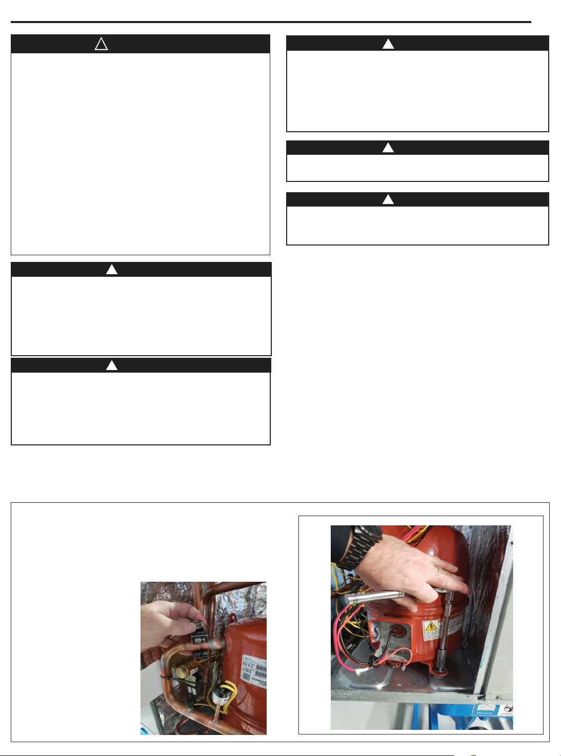
STEP 1 - Recover refrigerant, disconnect power leads
and remove mounting washers/nuts and set aside
from the existing compressor. Also disconnect LPCO
wires from the wire termination point. If a start kit is
installed, remove it.
Important: Make certain that the unit has been installed in
a level position to ensure proper draining.
IMPORTANT: Proper refrigerant charge and proper air flow are
critical to achieve rated capacity and efficiency. Installation of
this product should follow the manufacturer’s refrigerant charging
and air flow instructions. Failure to confirm proper charge and
airflow may reduce energy efficiency and shorten equipment
life.
IMPORTANT: Reconnect all grounding devices. All parts of this
product capable of conducting electrical current are grounded. If
grounding wires, screws, straps, clips, nuts, or washers used to
complete a path to ground are removed for service, they must be
returned to their original position and properly fastened.
IMPORTANT: Wear appropriate gloves, arm sleeve protectors,
and eye protection when servicing or maintaining this equipment.
Page 2
Page 3
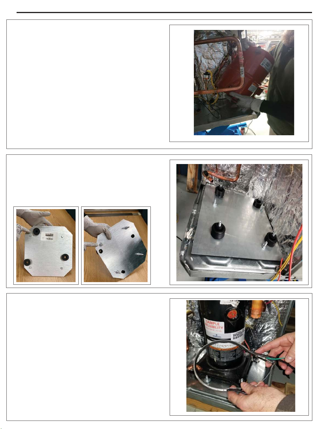
STEP 2 - Remove the compressor from the unit.
STEP 3 - Prior to setting base plate, install pallet
nuts, bolts and recip bushings onto the base plate.
Secure base plate into compressor compartment.
INSTALLER'S GUIDE
Note: Corners on provided base plate are cut.
STEP 4 -After securing the compressor to the
mounting plate using new grommets and screws,
slide the crankcase heater around the compressor,
tighten the mounting screw and secure the wires
out of the area that you will be brazing.
Note: Crankcase heater is for heat pump only.
Page 3
Page 4
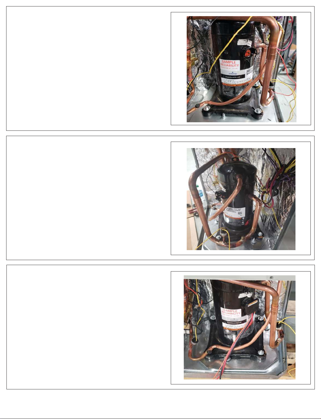
STEP 5 - Set the new compressor, tighten the
mounting nuts and use the Trane-supplied
tubing connectors to dry-fit the pipes before
brazing. Replace liquid line drier in the outdoor
coil section of the unit.
STEP 6 - Braze, leak check with nitrogen, vacuum
and recharge per data plate.
STEP 7 - Install new compressor power lead,
LPCO wires, connect crankcase heater wires and
secure any other wires that were moved during the
compressor replacement. Replace run capacitor if
required in parts notes.
Note: After and prior to start-up of the new compressor, ensure that all piping and wiring are not in
contact with the access panels when reinstalled.
Note: If discharge line vibration is an issue, order
part numbers CMP01450 & BAR00178 (clamp and
bar)
Note: If powered reverse rotation is a problem on
single-phase units, order part number RLY03032
(time delay relay).
Trane
6200 Troup Highway
Tyler, TX 75707
Since the manufacturer has a policy of continuous product and product
data improvement, it reserves the right to change design and specification
without notice.
 Loading...