

Page 1
USER'S
INFORMATION
MANUAL
For service and owner's use
32-5025-01
Model:
DCY024F1
DCY030F1
DCY036F1,3,4.
IMPORTANT --This Document is customer property andisto remain withthis unit. Please return to service information pack uponcompletion
ofwork.
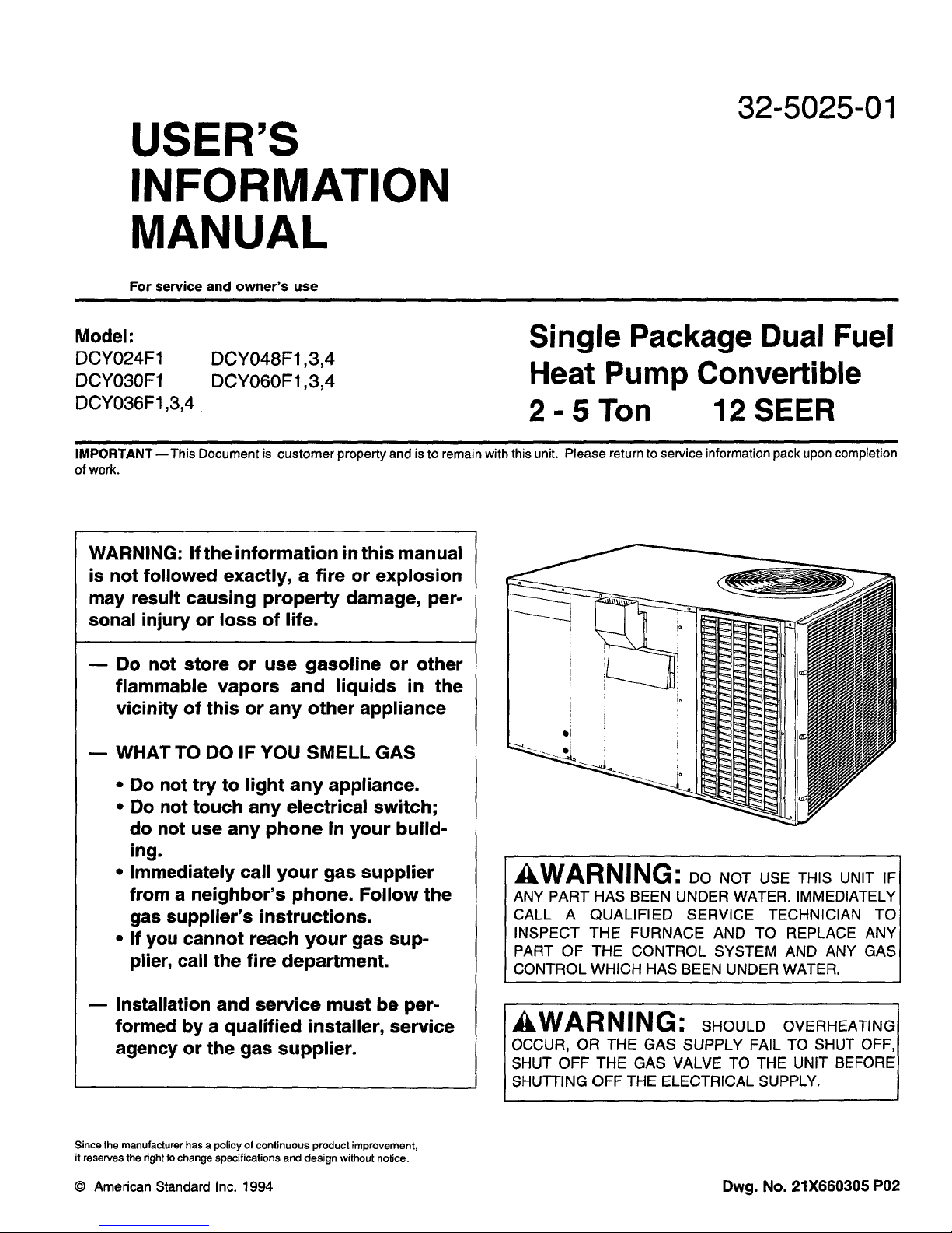
WARNING: If the information in this manual
is not followed exactly, a fire or explosion
may result causing property damage, per-
sonal injury or loss of life.
Do not store or use gasoline or other
flammable vapors and liquids in the
vicinity of this or any other appliance
-- WHAT TO DO IF YOU SMELL GAS
DCY048F1,3,4
DCY060F1,3,4
Single Package Dual Fuel
Heat Pump Convertible
2 - 5 Ton 12 SEER
• Do not try to light any appliance.
• Do not touch any electrical switch;
do not use any phone in your build-
ing.
• Immediately call your gas supplier
from a neighbor's phone. Follow the
gas supplier's instructions.
• If you cannot reach your gas sup-
plier, call the fire department.
Installation and service must be per-
formed by a qualified installer, service
agency or the gas supplier.
Since the manufacturer has a policy of continuous product improvement,
it reserves the right tochange specifications and design without notice.
© AmericanStandardInc. 1994 Dwg. No. 21X660305 P02
AWARNING: Do NOT USE THIS UNIT IF
ANY PART HAS BEEN UNDER WATER. IMMEDIATELY
CALL A QUALIFIED SERVICE TECHNICIAN TO
INSPECT THE FURNACE AND TO REPLACE ANY
PART OF THE CONTROL SYSTEM AND ANY GAS
CONTROL WHICH HAS BEEN UNDER WATER.
_kWARNING: SHOULDOVERHEATING
OCCUR, OR THE GAS SUPPLY FAILTO SHUT OFF,
SHUT OFF THE GAS VALVE TO THE UNIT BEFORE
SHUTTING OFF THE ELECTRICAL SUPPLY.
Page 2
GENERAL INFORMATION,,
OVERVIEW
Your combination dual fuel heat pump unit is designed to
comfort condition all year long with safe, efficient, trouble-
free operation. It is important that you understand how to
operate and maintain your unit to keep it operating safely and
efficiently. This manual will acquaint you with these impor-
tant procedures. Familiarize yourself with this manual and
store it in a convenient location for future reference.
Any additions, changes, or conversions required in order for
the unit to satisfactorily meet the application needs, should
be made by a qualified product distributor or local service
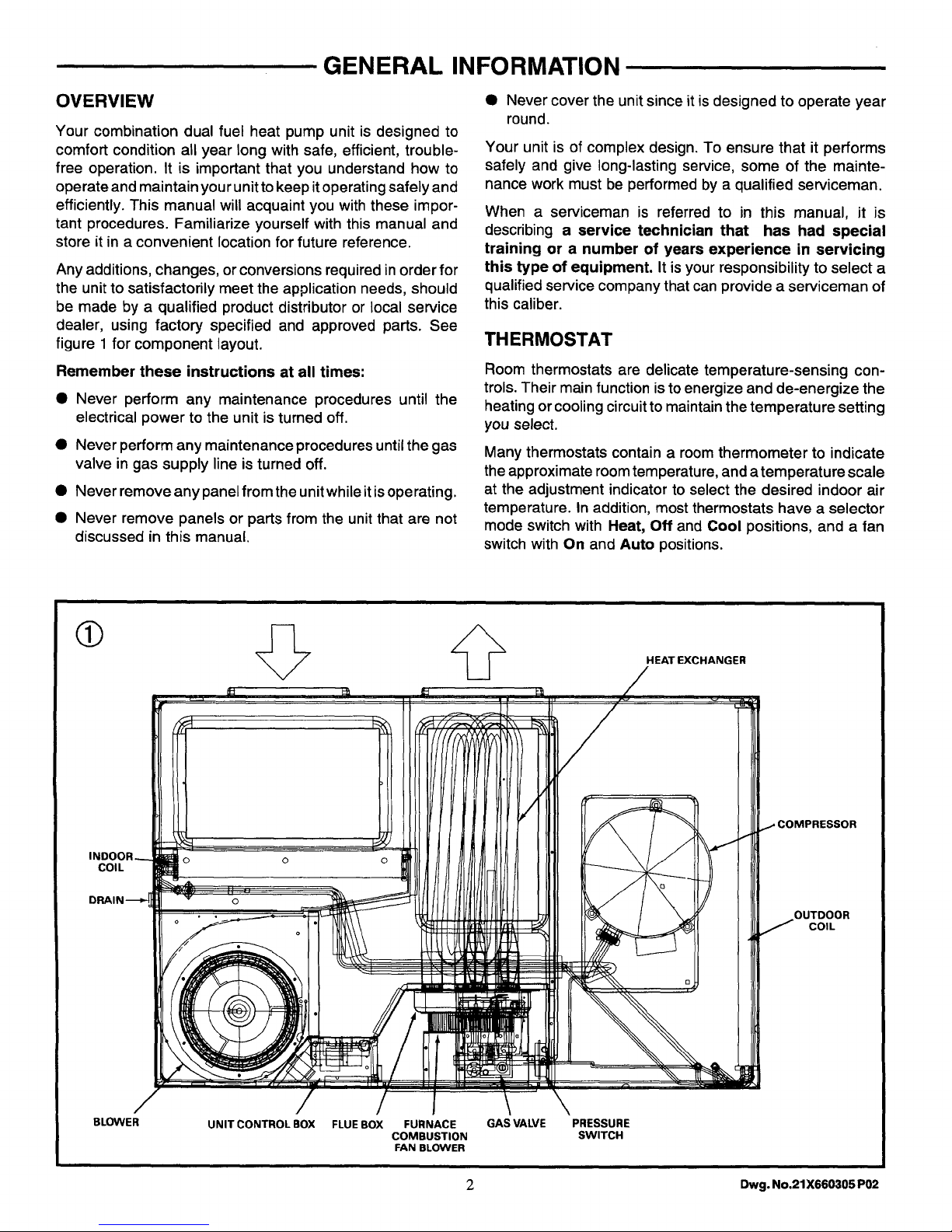
dealer, using factory specified and approved parts. See
figure 1 for component layout.
Remember these instructions at all times:
• Never perform any maintenance procedures until the
electrical power to the unit is turned off.
• Never perform any maintenance procedures until the gas
valve in gas supply line is turned off.
• Never remove any panel from the unit while itis ope rating.
• Never remove panels or parts from the unit that are not
discussed in this manual.
• Never cover the unit since it is designed to operate year
round.
Your unit is of complex design. To ensure that it performs
safely and give long-lasting service, some of the mainte-
nance work must be performed by a qualified serviceman.
When a serviceman is referred to in this manual, it is
describing a service technician that has had special
training or a number of years experience in servicing
this type of equipment. It isyour responsibility to select a
qualified service company that can provide a serviceman of
this caliber.
THERMOSTAT
Room thermostats are delicate temperature-sensing con-
trols. Their main function is to energize and de-energize the
heating orcooling circuit to maintain the temperature setting
you select.
Many thermostats contain a room thermometer to indicate
the approximate room temperature, and atemperature scale
at the adjustment indicator to select the desired indoor air
temperature. In addition, most thermostats have a selector
mode switch with Heat, Off and Cool positions, and a fan
switch with On and Auto positions.
COIL
o o o
o
o
HEAT EXCHANGER
//
OUTDOOR
COIL
BLOWER
UNIT CONTROL BOX FLUE BOX FURNACE GAS VALVE
COMBUSTION
FAN BLOWER
PRESSURE
SWITCH
2 Dwg. No.21X660305 P02
Page 3
GENERAL INFORMATION
Whenthe selector switch is positioned at Off your unit will not
operate in either heat or cool modes. Ifthe selector switch is
set at heat, the unit will automatically cycle on and off to
maintain the desired temperature settings. The unit will also
operate automatically when the selector switch is positioned
at Cool.
The fan selector switch can be used to operate the indoor fan
continuously by positioning it at On. When set at Auto, the
HEATING SYSTEM
HEATING CYCLE OPERATION
Your unit's heating system has a solid-state electronic
ignition control that lights thefurnace burners each time the
thermostat calls for heat. At the end of each heating cycle,
the furnace burners are extinguished. This type of system is
called Direct Spark Ignition (DSI).
A normal heating cycle begins when the air temperature in
your home drops below the thermostat setting. The thermo-
stat than energizes the heating electrical circuit that starts
and controls the furnace burners. Shortly after the burners
ignite, the indoor fan starts and circulates warm air through
your home.
When the air temperature rises to the thermostat setting, the
thermostatde-energizes the heating electrical circuit, which
in turn, extinguishes the furnace burners. The indoor fan
continues to circulate warm air until most of the heat is
removed from the unit's combustion chamber.
SAFETY CONTROLS
Your unit is equipped with an automatic reset safety limit
Controlto prevent overheating. When this control opens, it
shuts down the heating electrical circuit untilthe unit cools
downsufficiently.Inadequate airflow (i.e. caused by dirtyair
filters or defective fan motor), may cause the unit to cycle on
and off as the limitcontrol tripsand automatically resets. If
you suspect that the unit is cycling on its limit control,
immediately contact a serviceman for instructions.
Ifflames from the burner are notproperly drawn intothe heat
exchanger, a Flame Rollout Protection Control will open
causing the furnace to shut off. The cause must be investi-
gated by a qualifiedserviceman.
HEATING SYSTEM START-UP
Since your unit has an automatic ignition system, it is easy
to start the heating cycle at the beginning of the heating
season.
In order for this unit to operate properly and safely, the
furnace needs air for both combustion and ventilation.
Accordingly, observe the area in which the furnace is in-
stalled. Check to make sure that all the air openings are
unobstructed. Likewise, insure that the spacing around the
furnace it self is not blocked or obstructed.
fan will only operate when required during the heating or
cooling cycles.
To ensure that the thermostat operates properly, it must be
level and positioned to avoid the influence of such external
heat sources as lamps, televisions or other heat-producing
appliances.
1. Set the thermostat's heating adjustment lever at its
lowest setting; then move the selector switch to the Off
position.
2. Turn off all electric power to the unit.
3. This unit is equipped with an ignition device which
automatically lights the burners.
CAUTION: Never attempt to manually light the burner.
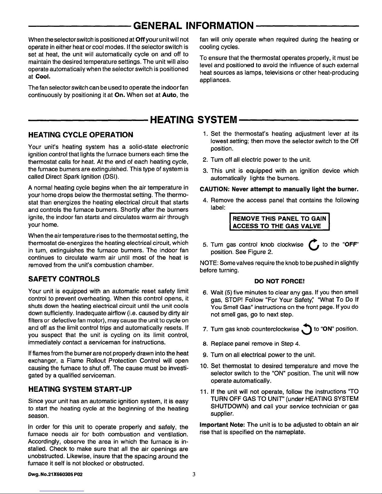
4. Remove the access panel that contains the following
label:
I REMOVE THIS PANEL TO GAIN I
ACCESS TO THE GAS VALVE
5.
Turn gas control knob clockwise _n to the "OFF"
position. See Figure 2.
NOTE: Some valves require the knob to be pushed inslightly
before turning.
DO NOT FORCE!
,
Wait (5) five minutes to clear any gas. If you then smell
gas, STOP! Follow "For Your Safety;' "What To Do If
You Smell Gas" instructions on the front page. If you do
not smell gas, go to next step.
.
Turn gas knob counterclockwise _ to "ON" position.
8.
Replace panel remove in Step 4.
9.
Turn on all electrical power to the unit.
10.
Set thermostat to desired temperature and move the
selector switch to the "ON" position. The unit will now
operate automatically.
11.
If the unit will not operate, follow the instructions 'q'O
TURN OFF GAS TO UNIT" (under HEATING SYSTEM
SHUTDOWN) and call your service technician or gas
supplier.
Important Note: The unit is to be adjusted to obtain an air
rise that is specifiedon the nameplate.
Owg. No.21X660305 P02 3
Page 4

HEATING SYSTEM
HEATING SYSTEM SHUTDOWN
To shut down the heating system for brief periods of time,
simply adjust the thermostat selector switch to the "OFF"
position.
If you need to turn the gas off to the unit, follow the steps
below:
TO TURN OFF GAS TO UNIT
1. Set the thermostat to lowest setting.
2. Turn off all electric power to the unit. If service is to be
performed.
3. Remove the access panel that contains the following
label:
I REMOVE THIS PANEL TO GAIN I
ACCESS TO THE GAS VALVE
The following warning complies with State of California law, Proposition 65.
WARNING: Th sproductcontains
fiberglass wool insulation! Fiberglass dust and ceramic
fibers are believed by the State of California to cause
cancer through inhalation. Glasswool fibers may also
cause respiratory, skin, or eye irritation.
4. Turn gas control knob clockwise _/ to the "OFF"
position. See Figure 2.
NOTE: Some valves require the knob to be pushed inslightly
before turning.
DO NOT FORCE!
5. Replace panel removed in Step 3 above.
CAUTION: If this is doneduring the cold weather months,
provisions must be taken to prevent freeze-up of all
water pipes and water receptacles. Whenever your home
orbuildingistobe vacant, arrange to have someone inspect
your structureforpropertemperature. This isvery important
in below freezing weather. If for any reason your furnace
should fail to operate, damage such as frozen water pipes
could result.
The following warning complies with State of California law, Proposition 65.
WARNING: Hazardous Gasses!
Exposure to fuel substances or by-products of incomplete
fuel combustion is believed by the state of California to
cause cancer, birth defects, or other reproductive harm.
COOLING SYSTEM
COOLING SYSTEM
START-UP AND OPERATION
Once electrical power is supplied to the unit, cooling opera-
tion is controlled by the thermostat. With the thermostat
selector switch set at COOL, move the cooling adjustment
lever to its lowest setting to energize the unit cooling system.
Now that the unit is operating, cool air will begin to circulate
through your building. Finally, reposition the cooling adjust-
ment lever to the desired room temperature; your unit will
continue to operate in the cooling mode automatically.
AIR FILTERS
AIR FILTERS
Filters are to be used with the DCY024-060F heating/cooling
units. The basic unit does not have filters in it. However, a
filter accessory is offered that will allow filters to be installed
in the unit. Otherwise a filter rack must be installed by the
installer in the duct work. Affix filter label supplied with the
unit adjacent to the filter area.
Filtersmust be installed in the return air system.
* Based on 300 FPM face velocity.
** Ifpermanent filters are used, be sure to size following the manufacturer's
recommendations with a clean filter resistance of 0.05 inches of water
column.
COOLING SYSTEM SHUTDOWN
If you wish toshut down thecooling system, the best method
is to move the thermostat selector switch to the OFF
position.
To shut down the unit completely, turn off the main electrical
power supply to the unit.
Anytime you think the cooling system is not operating
properly, shut down unit operation at the thermostat and
contact a serviceman for instructions.
TABLE 1 -- FILTER DATA
NOMINAL FILTER* FILTER
UNIT CFM (Sq Ft) SIZE RESISTANCE
DCY024F 800 2.67 0.05
DCY030 F 1000 3.33 0.05
DCY036F 1200 4.00 0.05
DCY048F 1600 5.33 0.05
DCY060F 2000 6.67 0.05
4 Dwg. No.21X660305 P02
Page 5

ROUTINE MAINTENANCE
You can do some of the periodic maintenance functions for
the unit yourself; this includes replacing (disposable) or
cleaning (permanent) the air filters, cleaning the cabinet,
cleaning the condenser coil, and conducting a general unit
inspection on a regular basis.
WARNING: BEFORE REMOVING UNITI
ACCESS PANELS TO SERVICE UNIT, OPEN UNITI
DISCONNECT SWITCH TO PREVENT INJURY OR I
DEATH DUE TO ELECTRICAL SHOCK OR CONTACT I
WITH MOVING PARTS. I
AIR FILTERS
It is very important to keep the central duct system air filters
clean. Be sure to inspect them at least once each month
when the system is in constant operation. (In new homes,
check the filters at least ever week for the first 4 weeks.)
If you have disposable-type filters replace them with new
filter of the same type and size. DO NOT ATTEMPT TO
CLEAN DISPOSABLE FILTERS.
Permanent-type filters can be cleaned bywashing them with
a mild detergent and water. Make sure that the filters are
thoroughly dry before reinstalling them in the unit. (or duct
system).
NOTE: It may be necessary to replace permanent filter
annually if washing fails to clean the filter, or if the filter shows
signs of deterioration. Be sure to use the same type and size
as was originally installed.
UNIT CABINET
Even though the unit cabinet is designed to withstand
exposure to outdoor weather, you can extend the life of the
cabinet panel by cleaning and waxing then twice each year.
Application of a light coat of automobile wax is recom-
mended.
CONDENSER COIL
Unfiltered air circulates throughthe units condenser coil and
can cause the coil's surface to become clogged with dust,
dirt, etc. To clean the coil, vertically (i.e., with the fins) stroke
the coil surface with a soft-bristled brush.
Be sure tokeep all vegetation away from the condenser coil
area.
GENERAL UNIT INSPECTION
Occasionally check over the unit; look and listen for unusual
or abnormal operating characteristics. Do not remove any
access panels. If you suspect your unit is not operating
properly, contact a serviceman for instructions.
MAINTENANCE PERFORMED BY SERVICEMAN
COOLING SEASON HEATING SEASON
To keep your unit operating safely and efficiently, The
Company recommends that a qualified serviceman check
over the entire system at least once a year, and any other
time that you feel one is needed. Your serviceman may
examine these areas of the unit:
1. filters (for possible cleaning)
2. motors (condenser and evaporator motors are perma-
nently lubricated)
3. gaskets (for possible replacement)
Complete the unit inspections and service routines de-
scribed below at the beginning of each heating season.
kWARNING: TOPREVE.TI.JURVORDEATH
DUETO ELECTRICALSHOCK OR CONTACTWITH MOVING
PARTS, LOCK UNIT DISCONNECT SWITCH IN OPEN
POSITIONBEFORE SERVICING UNIT.
/LWARNING: ToPREVENTA. EXPLOSION
ORPOSSIBLEINJURY,DEAT.ANDEQUIPMENTDAMAGE,
4. refrigerant coils (for possible cleaning)
5. safety controls (for mechanical cleaning)
6. electrical components and wiring (for possible re-
placement and connectiontightness)
7. condensate drain (for possiblecleaning)
8. inspect the unit duct connections to see that they are
physicallysound and sealed to the unit casing.
9. inspectthe unitmounting supporttosee that it issound.
10. inspect the unit to see that there is no obvious unit
deterioration.
DO NOT STORE COMBUSTIBLE MATERIALS, GASOLINE
OR OTHER FLAMMABLE VAPORSOR LIQUIDSNEAR THE
UNIT.
These steps should ONLY be performed by qualified service
technicians.
1. Inspect the control panel wiring and heating controls to
make sure connections are tight and wiring insulation is
intact.
a. Turn the unit on and off at the thermostat to be sure
the ignition control and spark electrode are operating.
Dwg. No.21X660305 P02 5
Page 6

MAINTENANCE PERFORMED BYSERVICEMAN
b. Turn offthe gas supply with the unit operating to verify
that the gas valve closes, and that a re-ignition cycle
is initiated by the ignition control.
2. Check the operation of the gas ignition system.
3. Check the burner manifold pressure. An 1/8-inch pipe
plug is provided in the gas valve for this purpose.
4. Inspect the control panel wiring to verify that all electrical
connections are tight, and that wire insulation, is intact.
5. Visually inspect all of the unit's flue product passage-
ways for excessive deposit buildup and corrosion. If
buildup or corrosion is apparent, perform the necessary
repairs.
The following warning complies with State of California law, Proposition 65.
ILWARNING: product contains
fiberglass wool insulation! Fiberglass dust and ceramic
fibers are believed by the State of California to cause
cancer throughinhalation. Glasswool fibers may also
cause respiratory,skin, or eye irritation.
6. Arrange for a qualified serviceman to inspect the unit
ever other heating season to maintain safe and efficient
operation.
7. Visually check the main burner flames. They should be
bright blue flames extending up to the heat exchanger
sections. (See Figure 2.)
8. Never store anything flammable or combustiblearound
or near the unit.
TUBE
- BURNER
PRECAUTIONARY MEASURES
• Avoid breathing fiberglass dust.
• Use a NIOSH approved dust/mist respirator.
• Avoid contact with the skin or eyes. Wear long-
sleeved, loose-fitting clothing, gloves, and eye
protection.
• Wash clothes separately from other clothing: rinse
washer thoroughly.
Operations such as sawing, blowing, tear-out, and
spraying may generate fiber concentrations requiring
additional respiratory protection. Use the appropriate
NIOSH approved respirator in these situations.
FIRST AID MEASURES
Eye Contact - Flush eyes with water to remove dust.
If symptoms persist, seek medical
attention.
Skin Contact
Wash affected areas gently with soap
and warm water after handling.
GAS VALVE
6 Dwg. No.21X660305 P02
Page 7

LIMITED WARRANTY
COMBINATION HEAT PUMP/GAS-ELECTRIC
DCY AND DCX MODELS
Models less than 20 tons for Residential use*
Single-phase electric power ....
(Parts Only)
This warranty is extended by American Standard Inc., to the original purchaser and to any
succeeding owner of the real property to which the Combination Heat Pump/Gas-Electric is
originally affixed, and applies to products purchased and retained for use within the U.S.A.
If any part of your Combination Heat Pump/Gas-Electric fails because of a manufacturing
defect within two years from the date of original purchase, Warrantor will furnish without
charge the required replacement part. Any local transportation, related service labor, diagno-
sis calls, air filters, refrigerant and related items are not included.
In addition, if the sealed motor-compressor or the outdoor coil becomes defective because of a
manufacturing defect within the third through tenth year from the date of original purchase,
Warrantor will furnish without charge a replacement compressor or outdoor coil. Any local
transportation, related service labor, diagnosis calls, refrigerant and related items are not
included.
In addition, if the steel heat exchanger fails because of a manufacturing defect within the third
through twentieth year from the date of original purchase, Warrantor will furnish without charge
a replacement heat exchanger. Any local transportation, related service labor and diagnosis
calls are not included.
This warranty does not cover failure of your Combination Heat Pump/Gas-Electric if it is
damaged while in your possession or if the failure is caused by improper maintenance or unrea-
sonable use. In no event shall Warrantor be liable for incidental or consequential damages. In no
event shall any implied warranty of merchantability or fitness for use exceed the term of
the limited warranty stated above.
Some states do not allow limitations on how long an implied warranty lasts or do not allow the
exclusion or limitation of incidental or consequential damages, so the above limitation or exclu-
sion may not apply to you. This warranty gives you specific legal rights, and you may also have
other rights which vary from state to state.
Parts will be provided by our factory or an authorized service organization in your area. All you
need do is look us up in the yellow pages or write to the address given below. If you wish further
help or information concerning this warranty, contact:
American Standard Inc.
Troup Highway
Tyler, Texas 75711-9010
Attention: Manager, Product Service
GW-535-1094
* This is a use other than commercial. A commercial use is any application where the end purchaser uses the product for other
than personal, family or household purposes.
Dwg. No.21X660305 P02 7
Page 8
LIMITED WARRANTY
COMBINATION HEAT PUMP/GAS ELECTRIC
DCY and DCX Models for Commercial Use*
Models less than 20 tons
Single or Three-phase electric power
(Parts Only)
This warranty is extended by American Standard Inc., to the original purchaser and to any
succeeding owner of the real property of which the Combination Heat Pump/Gas-Electric is
an original fixture, and applies to products purchased and retained for use within the U.S.A.
There is no warranty against corrosion, erosion or deterioration.
If any part of your Combination Heat Pump/Gas-Electric fails because of a manufacturing
defect within one year from the date of original purchase, Warrantor will furnish without charge
the required replacement part.
In addition, if the sealed motor-compressor fails because of a manufacturing defect within the
second through fifth year from the date of original purchase, Warrantor will furnish without
charge a replacement compressor.
In addition, if the steel heat exchanger fails because of a manufacturing defect within the second
through fifth year from the date of original purchase, Warrantor will furnish without charge a
replacement heat exchanger.
Warrantor's obligations and liabilities under this warranty are limited to furnishing, F.O.B.
factory or warehouse at Warrantor designated shipping point, freight allowed to Buyer's city,
replacement parts for Warrantor's products covered under this warranty. Warrantor shall not be
obligated to pay for the cost of lost refrigerant. No liability shall attach to Warrantor until prod-
ucts have been paid for and then liability shall be limited solely to the purchase price of the
equipment shown to be defective.
THE WARRANTY AND LIABILITY SET FORTH HEREIN ARE IN LIEU OF ALL OTHER
WARRANTIES AND LIABILITIES, WHETHER IN CONTRACT OR IN NEGLIGENCE,
EXPRESS OR IMPLIED, IN LAW OR IN FACT, INCLUDING IMPLIED WARRANTIES OF
MERCHANTABILITY AND FITNESS FOR PARTICULAR USE, IN NO EVENT SHALL
WARRANTOR BE LIABLE FOR ANY INCIDENTAL OR CONSEQUENTIAL DAMAGES.
American Standard Inc.
Troup Highway
Tyler, Texas 75711-9010
Attention: Manager, Product Service
* Commercial Use is any application where the end purchaser uses the product for other than personal, family or household
purposes.
GW-536-1094
American Standard Inc.
6200 Troup Highway
Tyler, TX 75711-9010
©American Standard Inc. 1994
8
Dwg. No.21X660305 P02
 Loading...