

Page 1

Trane Horizon
®
Absorption Series
Single-Stage Hot Water or
Steam-Fired Absorption Water Chillers
500-1350 Tons
Built for Industrial and Commercial Applications
ABS-PRC001-ENJune 2003
Page 2
Introduction
Hybrid Chiller Plant
A chiller plant design that allows the
operator to choose between multiple
energy sources is referred to as a hybrid
design. Hybrid chiller plants are
receiving increasing attention as
valuable options for facility owners.
There are various types of hybrid plant
designs. They encompass different
combinations of electric chillers and
other chiller types, including gas or
steam absorption chillers. The
advantages of having a choice of energy
sources will become even more viable
as we move further into the new
millennium.
Today we hear about utility deregulation.
For the first time, building owners can
negotiate power supply and natural gas
contracts with their traditional supplier,
as well as with new suppliers in the
market. The fuel-switching flexibility of
the hybrid plant puts the owner in a
much stronger negotiating position.
Similarly, many electric utilities offer
attractive off-peak or dual fuel electric
rates for applications which are not
operating during peak electric system
demand, most commonly in the
summer months. This represents an
opportunity for building owners who can
switch to a gas or steam system.
ABS-PRC001-EN© 2003 American Standard Inc. All rights reserved.
Page 3

Contents
Trane Horizon® Absorption
Series
Trane has led in absorption chiller design
and manufacturing for four consecutive
decades. In fact, Trane is the only North
American chiller manufacturer to
commercialize double-effect absorption,
over 25 years ago. With over 10,000
absorption chillers manufactured and
shipped, Trane serves the commercial,
industrial and process worldwide
markets. Microelectronic controls,
adaptive frequency drives and smart
purge systems have modernized the
technology, making it more capable,
more reliable and, in many applications,
more economical.
Performance
• Produces colder chilled water to 40°F
[4.4°C].
• Starts with low 55°F [12.8°C] towerwater temperatures.
• Operates reliably with low 65°F [18.3°C]
tower-water temperatures.
Easier Installation
• Rigging eyes built-in as standard.
• Shell disassembly option.
• Crossover pipe and steam valve
available as an option.
Reliability
• Adaptive microprocessor controls.
• 50,000 hours life-extended pumps.
• Constructed of corrosion-resistant alloy
materials.
Design Diversity
• Marine water boxes on cooling-water
connections available as an option.
• Custom design options available.
Introduction
Features and Benefits
Component Identification, Typical Single-Stage
Steam Illustration, Refrigerant Cycle Overview
Application Considerations
Operating Limits, Sound, Water Flow/Treatment,
Combination Systems, Multiple Machines
Selection Procedure
Computer Selection Procedure, Tube Fouling,
Product Coding Description
Performance Data
Capacity/COP/Steam Rate/Flow Rate, Pressure Drop
Tables, Capacity vs. Chilled Water Supply Temperature,
Energy Input vs. Capacity, Pressure Drop vs. Flow Rate
Electrical Data
Controls Data
Dimensions and Weights
Physical Dimensions, Weights, Connection Sizes,
Refrigerant Charging, Separated Machine Sections,
Foundation Support, Rigging/Service Clearances,
Chiller Isolation, Insulation Lengths
Jobsite Connections
Typical Piping
2
4
8
9
12
17
20
24
34
ABS-PRC001-EN
Mechanical Specifications
Standard/Optional/Design Special Features
Standard Conversion Table
40
42
43
3
Page 4
Features and
Trane Horizon® Absorption
Series, Single-Stage Hot
Water- or Steam-Fired
Absorption Water Chillers,
500-1350 Tons
Technology You Can Trust
In the early 1990’s, with the assistance of
the Gas Research Institute, Trane began
developing an innovative series of
absorption chillers. In 1995, Horizon
chillers began shipping from the Trane
manufacturing facility in La Crosse,
Wisconsin. The Horizon chiller is so
advanced, it redefined industry
standards for absorption system
integrity. Horizon chiller performance,
efficiency and reliability far exceed that
of past and present absorption chillers.
Dynamic By Design
Because uninterrupted chiller service is
critical to your operation, Horizon chillers
are designed to make chilled water
reliably, even in the harshest industrial
application. Water-tower systems and
load requirements can challenge the
long-term operation of many standardgrade chillers. The industrial-grade
construction of the Horizon chiller
accounts for varying load and watertemperature changes, as well as dirty
tower water. They are built with
corrosive-resistant alloy metals, and
precision welded in an ISO 9001 qualitycertified facility. Only extended-life
pumps, valves and water boxes are
manufactured into their design. For
further dynamics, Horizon UCP2
adaptive microprocessor controls react
precisely to system diversification.
Quality construction, long-life
components and adaptive controls are
what make the Horizon dynamic by
design.
Operates With Energy-Saving,
Low-Pressure Steam or Hot Water
The Horizon family includes a singlestage, hot water- or steam-fired chiller
line. Able to produce chilled water in the
range of 40 to 60°F [4.4 to 15.6°C], these
machines use 12 psig [0.83 bar] lowgrade steam or 270°F [132°C] hot water.
Benefits
Making chilled water from these
comparatively low-temperature inputs is
particularly important for energy
conserving applications, such as wasteheat recovery, co-generation equipment
and solar-energy-powered cooling.
General
Using refrigerant water helps eliminate
refrigerant management or availability
concerns. Additionally, absorption
technology reduces the use of electric
energy.
ABS-PRC001-EN4
Page 5

Features and
Sophisticated Reliability
Horizon controls meet specifications for
stand alone or hybrid chiller control.
UCP2 adaptive controls are critical to
reliable operation. Trane controls are
compatible with Integrated Comfort
Systems (ICS), and are easily integrated
into the Tracer
plant system controllers with a single
twisted-pair communications cable.
Ideal for Process and Commercial
Applications
With Horizon chillers, the application
possibilities for the absorption machine
are expanded. Capabilities such as lower
tower flow, variable evaporator flow,
lower chilled-water temperatures and
advanced control capabilities make the
single-stage Horizon absorption chiller
ideal for both process and comfort
applications.
When Long-lived Reliability
Is Important
Trane has been a long-time proponent of
the use of high-quality materials in
absorption chiller designs. The lithium
bromide temperatures and water
refrigerant, typical of all absorbers, can
more quickly corrode lower-grade metals
in the presence of air. Trane recommends
and uses industrial-grade materials to
provide long-lived, reliable cooling.
®
family of flexible chiller-
™
Benefits
A Global Network of
Absorption Expertise
When you specify a Trane Horizon
chiller, you’re getting the knowledge,
expertise and assistance of a pool of
experts that have decades of absorption
expertise. Making The Trane Company
part of your management team gives
you access to refrigeration, air
conditioning and facility control-system
applications specialists, and a unique
breadth of innovative solutions to satisfy
your facilities needs for today and
tomorrow.
Standard Specification For
Single-Stage Horizon Chillers
• C.O.P. 0.70
• Victaulic
• Fully-automatic purge system
• Industrial-grade tubes
— Generator .028" wall, 90/10
— Evaporator .025" wall copper
— Absorber 500-800 tonnages .022"
— Condenser .028• wall copper
• Advanced cycle-management system
with Adaptive Frequency
solution control
• 150 psig [10.3 bar] evaporator, absorber
and condenser sections
• Industrial-grade energy valve
• Rigging eyes for easy installation
• Advanced microprocessor control
system with adaptive control functions
• 2-line, 40-character clear-language
interface to unit functions and
diagnostic information
• Fixed and floating generator tube
supports prevent thermal stress
• Efficient stainless steel brazed plate
solution heat exchanger
• Long-life solution pumps
• Molybdate inhibitor system
• Factory-installed and-commissioned
controls
• Individually replaceable tubes
• Removable absorber and evaporator
spray trees
™
water connections
Cupro-nickel
(enhanced)
wall 95/5 Cupro-nickel 975-1350
tonnages .028" wall copper
™
drive
General
Optional Specification For
Single-Stage Horizon Chillers
• Removable absorber and evaporator
spray trees150 psig [10.3 bar] raised
face flanges for the evaporator,
condenser, and absorber water
connections
• Disassembled unit — eases
disassembly and reassembly of major
components at the job site
• Lithium bromide filter
• Condenser and absorber marine style
water boxes
• Factory installed cooling-water
crossover pipe absorber to condenser
• Factory mounted energy valve
• Choice of tube materials and other
chiller options
• Stainless steel evaporator pan
Absorption Cooling —
A Sound Decision
Life-cycle costing has become a primary
concern for chiller buyers who have
long-term investment opportunity in
mind. Changes in the distribution and
pricing of electricity have made the
absorption water chiller a popular choice
when alternative energy use makes
sense. Ask your local Trane
representative for a comprehensive
analysis of your facility, and the energysaving opportunities Trane offers for the
design of Heating, Ventilating and Air
Conditioning systems and controls.
ABS-PRC001-EN
5
Page 6
Features and
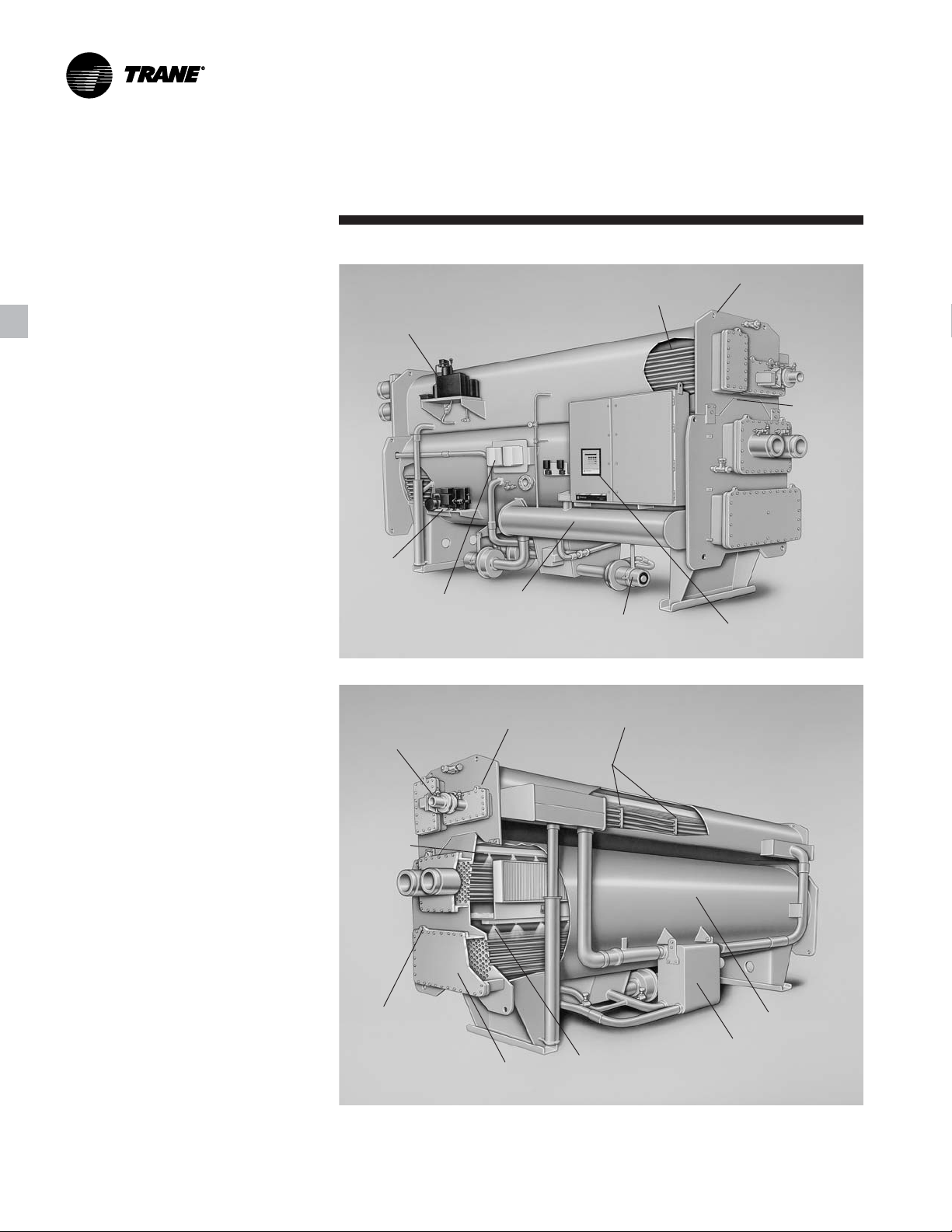
Component
Benefits
Fully-Automatic
Purge System
Vacuum
Pump
Solution Pump
Variable-Frequency
Drive
Refrigerant
Storage Tank
Identification
Condenser
Section
Long Life Hermetic
Solution Pumps
Rigging Eyes For
Easier Installation
Separable
Shell
Design
™
UCP2
Microprocessor
Control System
Industrial-Grade
Energy Valve
Evaporator
Spray Tree
Lifting Eyes on
Water Box Covers
ASME-Rated
Generator
Absorber Section
Fixed and floating tube supports
Industrial-grade tubes
Absorber
Spray Tree
Efficient Stainless-Steel
Solution Heat Exchanger
Evaporator
Section
ABS-PRC001-EN6
Page 7

Features and
Refrigeration
Horizon Single-Stage
Absorption Refrigeration Cycle
Refrigeration Cycle
This is an example of typical machine
operation at a standard rating point
condition (i.e., 85°F [29.4°C] tower, 44°F
[6.7°C] leaving chilled water) at full load.
Dilute solution has a relatively high
refrigerant content and low lithium
bromide content. An intermediate
solution is a mixture of dilute and
concentrated solutions. A concentrated
solution is one with a relatively low
refrigerant content and high lithium
bromide content.
Generator (1)
Dilute solution is pumped into the
generator, where it is boiled by the
steam or hot water in the tube bundle,
creating refrigerant vapor. The
refrigerant vapor flows to the condenser
(2). The now-concentrated solution
flows by gravity, through the solution
heat exchanger to the absorber spray
system, where it is mixed with dilute
solution from the absorber and sprayed
on the absorber tube bundle.
Condenser (2)
Refrigerant vapor, produced by the
generator, enters the condenser and
changes to a liquid through
condensation. The heat of condensation
is rejected to the cooling water inside the
tube bundle.
Evaporator (3)
The liquid refrigerant leaves the
condenser through a J tube, where the
pressure/temperature is reduced
through expansion for delivery to the
evaporator at 41°F [5°C]. System water
runs through the tube bundle where its
heat is transferred to the refrigerant,
causing the refrigerant to vaporize/boil.
The refrigerant vapor flows to the
slightly lower pressure in the absorber.
Absorber (4)
Refrigerant vapor is absorbed by the
lithium bromide solution. The now-dilute
solution is pumped through the solution
heat exchanger and on to the generator.
The heat of vapor absorption is rejected
via the cooling water inside the tube
bundle.
Benefits
Figure FB-1. Single-stage absorption refrigeration cycle
(1) Solution 215°F [102°C], Vapor 207°F [97°C]
(6)
Absorption Process (5)
Solution (concentrated) enters the spray
system from the generator and enters
the spray system, wetting the tubes and
providing a liquid surface for the
refrigerant vapor (from the evaporator)
to absorb into the lithium bromide
solution. The solution temperature/
concentration sprayed in the absorber
controls the absorber pressure, thereby
controlling the evaporator refrigerant
temperature.
Cycle
(5) Entering
Solution Heat Exchanger (6)
Solution flows through the heat
exchanger to be preheated, reducing the
heat energy required to induce boiling
within the generator, and to decrease the
temperature of the solution being
returned to the absorber, thus
decreasing the load on the cooling
tower.
(2) Refrigerant 100°F [38°C], Entering/
Leaving Cooling Water
94°F/102°F [34°C/39°C]
(3)
Entering/Leaving System
Water 54°F/44°F [12°C/7°C],
Evaporator Pump
Refrigerant 41°F [5°C]
(4) Leaving Solution 107°F
[42°C], Entering/Leaving
Cooling Water 85°F/94°F
Solution
120°F [49°C]
[29°C/34°C]
ABS-PRC001-EN
7
Page 8

Application
General
The Horizon single-stage steam-fired or
hot water absorption chiller is designed
to provide 40°F to 60°F [4.4°C to 15.6°C]
chilled water, for comfort or process
cooling applications, within all three
market segments – commercial,
industrial and institutional. They are
most-often used where an economic
analysis of fuel costs versus electrical
rates indicates an operating cost
advantage.
In many process applications, they can
be utilized to convert excess heat energy
to provide chilled water for process or
comfort applications.
Operating Limits
Trane single-stage absorption chillers
operate with nominal 12 psig [0.83 bar]
steam or nominal 270°F [132°C] hot
water. In all applications, superheat
should be limited so steam temperature
does not exceed 340°F [171°C].
Waterflows that are within the limits
indicated on the appropriate selection
table will ensure tube water velocities
not exceeding 10 feet per second
[3.05 m/sec] in copper tubes and 11 feet
per second [3.35 m/sec] in cupronickel
tubes. Changes in condenser water
temperature should not exceed
1°F per minute in the range from 75°F to
95°F [23.9°C to 35°C].
Sound and Vibration
Absorption units are well-suited for
areas where low sound levels are
required. The Trane Horizon single-stage
steam absorption chiller will operate
under normal load conditions at less
than 85 dBA sound pressure level.
During operation there is no vibration of
any components that could be
damaging to the chiller or that could
transmit objectionable sound or
vibration to the building.
Considerations
Chiller Installation
The following should be considered
when installing an absorption chiller:
• Rigging and service clearances
• Foundation support
• Chiller isolation for sound/vibration
reduction
• Condensate handling
• Steam supply control
• Condenser-water temperature control
• Chilled-water flow control
• Chilled- and condenser-water flow limit
• Generator hot-water application
Cooling-Tower Water Flow
The ARI standard gpm/ton for singlestage absorption chillers is 3.6, however,
lower flow through the condenser and
absorber section will present an
opportunity for a smaller tower, smaller
piping, and smaller condenser pump.
For more information on lower flows in
the cooling tower water circuit, refer to
the appropriate Trane engineering
bulletin, available from your local Trane
representative.
Water Treatment
The use of untreated or improperly
treated water may result in scaling,
erosion, and corrosion, algae or slime. It
is recommended that the services of a
qualified water-treatment specialist be
used to determine what treatment, if
any, is advisable. The Trane Company
assumes no responsibility for the results
of untreated or improperly treated water.
Combination Systems
Peak energy savings can be achieved
when using a combination of electric
chillers and absorption chillers for air
conditioning loads. The absorption
chiller is used to shave seasonal, billable
peak-power demands during summer
operation, and the electric chiller is run
below the allowed demand limit,
reducing costly demand charges. Trane
offers both electric chillers and
absorption chillers with the unit control
panel (UCP2) as standard. Although the
General
chillers have different features and
modes of operation, the chiller control
panel looks and acts the same when
used with any chiller model. Each
control panel is programmed to monitor
the particular chiller for which it was
designed, however, maintenance and
service personnel only need to become
familiar with one control panel.
Combined with a Trane Tracer
chiller plant has almost unlimited
operational flexibility, and all equipment
is supplied from a single source.
Multiple Machine Installations
The Trane absorption machine can be
applied to series or parallel chilled-water
flow, depending upon the design
requirement. The arrangement that is
best for an individual system should be
based on an analysis of system water
and temperature rise requirements,
system and machine pressure-drop
characteristics, and installation cost.
Parallel flow allows minimum chilledwater pressure drop through the
machines. However, with one machine
“off,” it is not usually possible to
maintain the design chilled-water
temperature unless one machine is
isolated with shut off valves and the
chilled-water flow decreased.
Series flow permits design chilled-water
temperature at light loads with one
machine “off.” However, at all operating
conditions, the chilled-water pressure
drop through the machine is high.
Accurate chilled-water temperatures can
be maintained on individual machines
between 100 percent and 10 percent of
nominal chiller load, which allows for a
wide range of control options. Each
chiller has a stand-alone control system
to manage the desired water
temperature, and also the ability to
receive remote commands to support
various system demands from a control
center. This versatility of control makes
the management of more than one
machine relatively easy.
®
system, a
ABS-PRC001-EN8
Page 9

Selection Procedure
Selection Procedure
Absorption refrigeration machines are
usually selected to provide the required
refrigeration capacity with the smallest
practical machine of sufficient size.
Machine size is based on chilled-water
flow rates and temperatures specified for
the air side of the system.
Total air-conditioning system first cost
can be minimized by a careful analysis of
system operating parameters. The effect
of flow rates and temperatures, on both
the building air side and the refrigeration
machine selections, should be
investigated to determine which system
represents the best investment for the
owner.
The information on the following pages
provides performance data, at ARI
standard conditions, for capacity in tons,
efficiency, flow rates and water pressure
drops. All capacities are in accordance
with the expected ARI 560 Standard
revision, and are based on fouling
factors of .0001 for the evaporator
waterside tubing and .00025 for the
absorber and condenser tubing.
Standard Fouling
Unit performance at non-standard
fouling factors may vary from standard
performance. Fouling factors estimate
the heat transfer penalty that coincides
with the effect of typical fouling in
evaporator and absorber/condenser
(cooling) water circuits. All selections
should use the standard fouling factor to
more accurately estimate the chiller
performance in an equipment room and
to comply with ARI 560.
ARI Standard Fouling Factors
Evaporator Condenser/Absorber
English Units – hr-ft2-F/Btu
0.0001 0.00025
SI Units – m2-K/kW
0.018 0.044
Additional Fouling
Any selection that uses a fouling factor
greater than 0.0001 for the evaporator
tubes, and 0.00025 for the condenser/
absorber tubes, is a more conservative
estimate that should only be used if
there is an abnormal amount of fouling
contaminants in the water systems. The
ARI 560 Standard defines “additional
fouling” as “Conditions such as water
hardness, organic material, suspended
solids and/or water velocity may
necessitate the use of a greater field
fouling allowance than that provided in
the Standard Rating of equipment.” The
Trane single-stage Horizon Selection
program should be used to determine
the effect of nonstandard fouling factors.
The following guidelines can be used for
estimation prior to the selection:
ARI Standard Fouling Factors For
Additional Fouling
Evaporator Condenser/Absorber
English Units – hr-ft2-F/Btu
0.0002 0.00026 – 0.00075
SI Units – m2-K/kW
0.035 0.046
Part Load Performance
The Horizon
®
single-stage absorption
chiller exhibits excellent part-load
performance characteristics. Air
conditioning system loads are usually
significantly less than full-load design
conditions. Therefore, the absorption
chiller operates at full load a small
percentage of the time. Part-load
absorption chiller operation is normally
associated with reduced tower-water
temperatures. At part-load operation, the
heat rejected to the cooling tower is less
than at full-load operation. Also, partload operation is typically associated
with reduced outside wet-bulb
temperatures, resulting in improved
cooling tower performance. The net
result of less heat rejection and lower
wet-bulb temperature is cooler tower
water entering the chiller and improved
unit performance.
Final Selection
A final selection must be done by the
local Trane sales engineer using the
Trane Horizon
®
Single-Stage Absorption
Selection Program. For applications
higher than 1600 feet [500 meters] above
sea level, final selection requires review
by Absorption Product Marketing. Prior
to accessing the computer selection
program, the following data inputs
should be tabulated:
• Temperature or pressure of the hot
water or steam
• Two of the following three values must
be provided
1
:
– Evaporator Delta-T
– Evaporator Flow
– Cooling Capacity
• Leaving-Evaporator Water Temperature
• Entering-Absorber Water Temperature
• Cooling Water Flow
• Chilled water and tower water fouling
factors
Other options that may also be selected
are:
• Type and thickness of tube material
• Type of solution flowing through the
evaporator and tower loop
1
Any limitations or restrictions should
2
.
also be given (i.e., pressure drop, gpm
etc.).
2
Absorption chillers can be selected with
a wide variety of media other than
water (evaporator and absorber/
condenser, or both). For media other
than water, contact the local Trane sales
office for chiller selections and
information.
ABS-PRC001-EN
9
Page 10

Selection
Product Coding
Procedure
Selection
Product Coding Description
The coding block precisely identifies all
characteristics of any Horizon® Single-Stage
Steam-Fired or Hot Water Absorption Chiller.
Table S-1. Product coding description
MODL Absorption Unit Model
ABSD Single Stage Absorption
NTON Unit Nominal Tonnage
500 500 Nominal Tons
600 600 Nominal Tons
700 700 Nominal Tons
800 800 Nominal Tons
975 975 Nominal Tons
1100 1100 Nominal Tons
1225 1225 Nominal Tons
1350 1350 Nominal Tons
VOLT Unit Voltage
190 190 Volt - 50 HZ
200 200 Volt - 60 HZ
220 220 Volt - 50 HZ
230 230 Volt - 60 HZ
380 380 Volt - 50 HZ
415 415 Volt - 50 HZ
460 460 Volt - 60 HZ
575 575 Volt - 60 HZ
ENSR Unit Energy Source
STM Steam Energy Source
HOTW Hot Water Energy Source
ENPR Unit Energy Pressure
50 Steam Energy Pressure - 50 PSIG
ASME Required
150 Hot Water Energy Pressure - 150
PSIG - ASME Required
400 Hot Water Energy Pressure – 400
PSIG - ASME Required
PVCN Pressure Vessel Construction
STD Standard Construction
Standard construction (includes
ASME LTGN)
PURG Purge System
AUTO Automatic Purge System
LGTM Generator Tubes
SB04 .028 Wall 90-10 CUNI Smooth
Surface
SB05 .035 Wall 90-10 CUNI Smooth
Surface
SB06 .049 Wall 90-10 CUNI Smooth
Surface
SB16 .028 wall 409 SST smooth surface
CDTM Condenser Tubes
SB09 .028 Wall Copper Smooth Surface
SB10 .035 Wall Copper Smooth Surface
SB04 .028 Wall 90-10 CUNI Smooth
Surface
SB05 .035 Wall 90-10 CUNI Smooth
Surface
SB06 .049 Wall 90-10 CUNI Smooth
Surface
SB17 .028w 316L SST Smooth Surface
Description
EVTM Evaporator Tubes
ES12 .025 Wall Copper Enhanced Surface
ES11 .025 Wall 90-10 CUNI Enhanced
Surface
ES05 .035 Wall 90-10 CUNI Enhanced
Surface
ABTM Absorber Tubes
SB00 .022 Wall 95-5 CUNI Smooth Surface
SB01 .028 Wall 95-5 CUNI Smooth Surface
SB02 .035 Wall 95-5 CUNI Smooth Surface
SB03 .049 Wall 95-5 CUNI Smooth Surface
SB04 .028 Wall 90-10 CUNI Smooth
Surface
SB05 .035 Wall 90-10 CUNI Smooth
Surface
SB06 .049 Wall 90-10 CUNI Smooth
Surface
SB09 .028 Wall Copper Smooth Surface
SB17 .028 Wall 316L SST Smooth Surface
GNWA LTGN - Generator Water Box
Arrangement
GN02 1-Pass Non-Marine RF Flange
GN04 2-Pass Non-Marine RF Flange
CAWA Condenser and Absorber Water Box
Arrangement
CA17 150 PSI Marine Victaulic
CA18 150 PSI Marine RF Flange
CA19 150 PSI Non-Marine Victaulic
CA20 150 PSI Non-Marine RF Flange
EVWA Evaporator Water Box Arrangement
EV31 1-Pass 150 PSI Non-Marine Victaulic
EV32 1-Pass 150 PSI Non-Marine RF Flange
EV01 2-Pass 150 PSI Non-Marine Victaulic
EV02 2-Pass 150 PSI Non-Marine RF Flange
CAWC Condenser and Absorber Water
Connections
RERE In right-hand end – out right-hand
end (700, 800, 1000, 1100, 1200 tons)
LELE In left-hand end – out left-hand end
(500 tons)
LERE In left-hand end – out right-hand end
(600 and 900 tons)
EVWC Evaporator Water Connections
LEBK Inlet Connection Left Back
LEFR Inlet Connection Left Front
REBK Inlet Connection Right Back
REFR Inlet Connection Right Front
LEND In left end, out the other end
REND In right end, out the other end
CAFT Condenser and Absorber Water Box
Fluid Type
WTR Water
EGLY Ethylene Glycol Solution
PGLY Propylene Glycol Solution
EVFT Evaporator Water Box Fluid Type
WTR Water
EGLY Ethylene Glycol Solution
PGLY Propylene Glycol Solution
ABS-PRC001-EN10
Page 11

Selection
Product Coding
Procedure
EVLV Unit Energy Valve
BF02 2-Way 3" 150# Wafer Btrfly
BF03 2-Way 4" 150# Wafer Btrfly
BF04 2-Way 6" 150# Wafer Btrfly
BF05 2-Way 8" 150# Wafer Btrfly
BF22 3-Way 3" 150# Flanged tee Wafer
Btrfly
BF23 3-Way 4" 150# Flanged tee Wafer
Btrfly
BF24 3-Way 6" 150# Flanged tee Wafer
Btrfly
BF32 3-Way 3" 300# Flanged tee Wafer
Btrfly
BF33 3-Way 4" 300# Flanged tee Wafer
Btrfly
BF34 3-Way 6" 300# Flanged tee Wafer
Btrfly
BF42 2-Way 3" 150# Flanged Btrfly
BF43 2-Way 4" 150# Flanged Btrfly
BF44 2-Way 6" 150# Flanged Btrfly
BF45 2-Way 8" 150# Flanged Btrfly
VB01 2-Way 2" 150# Wafer V-Ball
VB02 2-Way 3" 150# Wafer V-Ball
VB03 2-Way 4" 150# Wafer V-Ball
VB11 2-Way 2" 300# Wafer V-Ball
VB12 2-Way 3" 300# Wafer V-Ball
VB13 2-Way 4" 300# Wafer V-Ball
VB41 2-Way 2" 150# Flanged V-Ball
VB42 2-Way 3" 150# Flanged V-Ball
VB43 2-Way 4" 150# Flanged V-Ball
EVIN Unit Energy Valve Installation
FLD Field-installed Energy Valve
FACT Factory-installed Energy Valve
EVPN Evaporator Pan construction
STD Evaporator Pan – Steel
SSTL Evaporator Pan – Stainless Steel
UPNT Unit Paint
SFPT Standard Factory Paint – Entire Unit
CSPT Customer Specified Paint – Entire
Unit
WCNM Water Chiller Nameplate
SNMP Standard ABS Water Chiller
Nameplate
BNMP Decorative Brass ABS Water Chiller
Nameplate
SPKG Unit Shipping Package
DAU Domestic – Assembled Unit
DDG Domestic – 2-Piece Disassembled
Unit
DAGF Domestic – Assembled - 2-Piece Field
Disassembly
EAU Export – Assembled Unit
EDG Export – 2-Piece Disassembled Unit
EAGF Export – Assembled - 2-Piece Field
Disassembly
Description
ELPP Electrical Protection Package
SELP Standard Electrical Package
PPCO Control Panel Power Connection
CB Circuit Breaker
FDS Fused Disconnect Switch
NFDS Non-Fused Disconnect Switch
TB Terminal Block
LCLD Local Clear Language Display
CLDC Clear Language Display – Complex
Character
CLDO Clear Language Display – Suitable for
Outdoor Use
TRIM Tracer Interface Control Module
TRMI Tracer 100 Interface Module (com3)
TRMS Tracer Summit Interface Module
(com4)
PRIM Printer Interface Control Module
YES Printer Interface Module
ACWR Ambient Chilled Water Reset
YES Ambient Chilled Water Reset
WVUO Under/Over Phase Voltage
Protection
YES Under/over Voltage Protection
CTWF Chiller/Tower Water Flow Display
YES Differential Water Pressure
Transducers
OPTM Options Control Module
YES Options Module
AFDS Adjustable frequency drive
YES Frequency drive
FLSW Flow Switches
1FS1 150 PSI NEMA 1 Flow Switch
- QTY of 1
1FS2 300 PSI NEMA 1 Flow Switch
- QTY of 1
1FS3 150 PSI NEMA 4 Flow Switch
- QTY of 1
1FS4 300 PSI NEMA 4 Flow Switch
- QTY of 1
2FS1 150 PSI NEMA 1 Flow Switch
- QTY of 2
2FS2 300 PSI NEMA 1 Flow Switch
- QTY of 2
2FS3 150 PSI NEMA 4 Flow Switch
- QTY of 2
2FS4 300 PSI NEMA 4 Flow Switch
- QTY of 2
LBMF Lithium Bromide Filter
Yes Lithium Bromide Filter
UINS Unit Insulation
CINS Cold Unit Insulation Only
CRPI Condenser Cross-Over pipe
Yes Condenser cross-over pipe,
factory installed
ABS-PRC001-EN
11
Page 12
Performance Data
Table PD-1. Performance data at ARI conditions
Capacity of Rate Flow Rate Press. Drop Flow Rate Press. Drop
Coefficient Steam Chilled Water Cond/Abs Water
Model (Tons) Performance (lbm/ton/hr) (gpm) (ft Wtr) (gpm)*** (ft Wtr)
ABSD500 571 0.71 17.71 1366 19.7 1800 27.4
ABSD600 670 0.72 17.45 1603 30.2 2160 26.6
ABSD700 738 0.71 17.68 1766 22.3 2520 12.2
ABSD800 859 0.72 17.62 2054 32.6 2880 16.6
ABSD975 998 0.71 17.91 2387 18.8 3510 33.5
ABSD1100 1105 0.70 17.98 2643 24.6 3960 20.1
ABSD1225 1238 0.70 17.95 2960 32.7 4410 25.7
ABSD1350 1371 0.71 17.90 3279 42.2 4860 32.2
* 3.6 gpm/nominal ton, Pstm = 12 psig, TctwS = 85°F, TcwS = 44°F, TcwR = 54°F, 0.0001 evap fouling,
0.00025 cond/abs fouling
Coefficient Steam Chilled Water Cond/Abs Water
Capacity of Rate Flow Rate Press. Drop Flow Rate Press. Drop
Model (kW) Performance (kg/kW-hr) (m
ABSD500 2008 0.71 2.28 310 6.0 409 8.3
ABSD600 2356 0.72 2.25 364 9.2 491 8.1
ABSD700 2595 0.71 2.28 401 6.8 572 3.7
ABSD800 3021 0.72 2.27 466 9.9 654 5.1
ABSD975 3510 0.71 2.31 542 5.7 797 10.2
ABSD1100 3886 0.70 2.32 600 7.5 899 6.1
ABSD1225 4354 0.70 2.31 672 10.0 1002 7.8
ABSD1350 4821 0.71 2.31 745 12.9 1104 9.8
** 0.23 m3/nominal kWh, Pstm = 0.83 bar, TctwS = 29.4°C, TcwS = 6.67°C, TcwR = 12.2°C, 0.018 evap fouling,
0.044 cond/abs fouling
English Units*
SI Units**
3
/hr) (m wg) (m3/hr) (m wg)
ABS-PRC001-EN12
Page 13

Performance
Data
Figure PD-1. ABSD 500-800 capacity vs. chilled-water supply temperature at various
cooling-water supply temperatures
Figure PD-2. ABSD 975-1350 capacity vs. chilled water supply temperature at various
cooling water supply temperatures
ABS-PRC001-EN
13
Page 14
Performance
Data
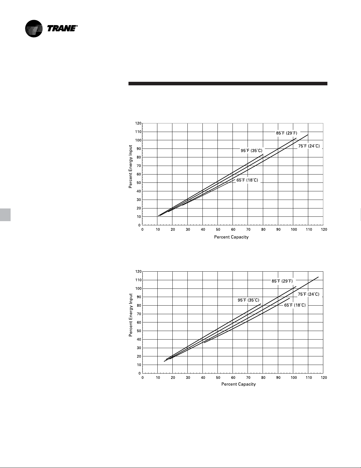
Figure PD-3. ABSD 500-800 part load performance - energy input vs. capacity at various
cooling water supply temperatures:
chilled water supply temperature = 44°F (7°C)
Figure PD-4. ABSD 975-1350 part load performance - energy input vs. capacity at various
cooling water supply temperatures:
chilled water supply temperature = 44°F (7°C)
ABS-PRC001-EN14
Page 15

Performance
Pressure Drop vs.
Data
Figure PD-5. ABSD 500-800 pressure drop vs. chilled water flow rate – English and SI Units
Water Flow Rate
Figure PD-6. ABSD 975-1350 pressure drop vs. chilled water flow rate – English and SI Units
ABS-PRC001-EN
15
Page 16

Performance
Pressure Drop vs.
Data
Figure PD-7. ABSD 500-800 pressure drop vs. cooling water flow rate – English and SI Units
Water Flow Rate
Figure PD-8. ABSD 975-1350 pressure drop vs. cooling water flow rate – English and SI Units
ABS-PRC001-EN16
Page 17

Electrical Data
Electrical Data
Factory-wired and-mounted power control includes main power connections. Total kW includes solution and refrigerant pump,
motors, purge pump motor and control panel. Units may be supplied for operation on 230,460 or 575 volt, 3-phase, 60-hertz
power, or 190, 220, 380 or 415 volt, 3-phase, 50-hertz power.
Table ED-1. Electrical data
Model Voltage FLA HP kW Amps MCA Amps
500 200 69.0 13.0 9.7 10.0 86 90
thru 230 60.0 13.0 9.7 8.7 75 80
600 460 30.0 13.0 9.7 4.4 37 40
700 200 90.0 17.5 13.0 10.0 109 110
thru 230 78.0 17.5 13.0 8.7 94 100
800 460 39.0 17.5 13.0 4.4 47 50
975 230 78.0 17.5 13.0 8.7 94 100
1100 200 96.0 20.0 14.9 10.0 115 125
thru 230 84.0 20.0 14.9 8.7 100 110
1350 460 42.0 20.0 14.9 4.4 50 60
Model Voltage FLA HP kW Amps MCA Amps
500 190 62.0 13.0 9.7 10.5 79 80
thru 220 52.4 13.0 9.7 9.1 67 70
600 380 30.0 13.0 9.7 5.3 38 40
700 190 67.0 15.5 11.6 10.5 85 90
thru 220 57.4 15.5 11.6 9.1 73 80
800 380 33.0 15.5 11.6 5.3 42 45
975 190 80.0 17.5 13.0 10.5 98 100
1100 190 85.0 20.0 14.9 10.5 103 110
thru 220 73.0 20.0 14.9 9.1 89 90
1350 380 42.0 20.0 14.9 5.3 51 60
Supply Total Motor Total Motor Control Circuit Max Fuse Size
575 25.0 13.0 9.7 3.5 31 35
575 32.0 17.5 13.0 3.5 39 40
200 90.0 17.5 13.0 10.0 109 110
460 39.0 17.5 13.0 4.4 47 50
575 32.0 17.5 13.0 3.5 39 40
575 34.0 20.0 14.9 3.5 41 45
Supply Total Motor Total Motor Control Circuit Max Fuse Size
415 27.5 13.0 9.7 4.8 35 35
415 30.5 15.5 11.6 4.8 39 40
220 68.0 17.5 13.0 9.1 84 90
380 39.0 17.5 13.0 5.3 48 50
415 36.0 17.5 13.0 4.8 44 45
415 39.0 20.0 14.9 4.8 47 50
60 Hertz, 3-Phase
50 Hertz, 3-Phase
ABS-PRC001-EN
17
Page 18

Electrical
Data
Wiring
ABS-PRC001-EN18
Page 19

Electrical
Data
Wiring
ABS-PRC001-EN
19
Page 20

Controls Data
Setting The Standards
Trane set the standard for unit
microprocessor controls in 1985 with the
first generation of Unit Control Panel.
Associated with this standard have been:
• Proportional Integral Derivative (PID)
control strategies, which provide stable
operation and high accuracy for better
performance, along with feed forward
plus;
• Adaptive Control
™
to keep the chiller
“on line” and at the same time keep the
chiller away from a major failure;
• Software based safeties that do not
depend on electromechanical hardware
– hardware that means questionable
reliability and added cost;
• Operator interface that accesses chiller
information and control adjustments at
the front of the panel.
™
UCP2
UCP2 adds more flexibility, more
reliability and better system performance
than even our most demanding
customers expect.
Flexibility
Trane offers the ability to adapt to
changes easily and effectively without
adding prohibitive cost. To provide
flexibility, the controller responds to a
wide variety of needs for:
• System Designs, including equipment,
operating conditions and controls
variations that are either existing or
being considered for new installations.
Key to designing non-traditional
systems is the ability to evaluate the
cost and reliability issues of these
systems in comparison to the more
traditional systems. Trane recommends
the use of C.D.S. Network Equipment
Economics, the Trane Applications
Manuals and consultation with a Trane
sales engineer for help in this analysis.
• System Upgrades, including the ability
to accommodate changes in the chilledwater system design or equipment
room requirements, or to
accommodate new technologies that
become available.
• Modular structure of the UCP2 makes it
possible for the designer to select the
system controls and associated
interfaces to Tracer
®
(or other building
automation systems) that are required
for the chiller plant design. With this
modular concept, capability can be
added or upgraded at any time, with
only temporary interruption of chilledwater production.
• The operator can quickly program a
Custom Report — so that only what are
considered to be the most frequently
accessed/important reports are
available — at any time, right at the
front of the panel.
• With easy front panel programmability
of Daily, Service Start-up and Machine
Configuration settings and setpoints,
the operator, serviceman and system
designer can customize the use of the
micro controller to unique conditions of
the chiller plant — whether the purpose
of chilled water is for comfort cooling or
for process cooling.
• All data that is necessary for the safe
operation and easy serviceability of the
chiller is provided as standard on all
Horizon
®
absorption chillers. Options
are available that provide additional
controls/data that are required for: an
industrial/process system design,
applications outside of the typical
chilled water system design, the need
for redundant machine protection or the
desire for more system information.
ABS-PRC001-EN20
Page 21

Controls Data
Reliability
To most people, reliability means
“dependability — giving the same result
on successive trials.” To our customers,
however, it has come to mean “keep
chilled water flowing.” In other words,
“when I turn the switch on, cold water
comes out.” In order to do this, the
micro controller must be aware of what
is happening in the system. But more
importantly, it must be able to make
decisions and adjustments to keep the
chiller running as long as possible, even
when non-standard conditions exist —
conditions such as bad power, bad water
(flow, temperature, fouling) or system
component failure. Also, the Trane UCP2
panel continuously monitors for
noncondensables and purges
automatically.
• With Enhanced Adaptive Control
controller does everything it can to
avoid taking the chiller offline.
— Senses evaporator temperature
limit and high temperature limit
— Displays a warning message about
the potential condition/safety trip
— Takes the following corrective action
sequentially as the condition
worsens:
- limits loading
- prevents further loading
- unloads until condition improves
- takes chiller offline
• With more diagnostics and diagnostic
history that are time/date stamped and
with help messages, the operator or
serviceman can take faster and more
effective corrective action.
™
the
System Performance
“Chilled Water System” encompasses
many levels of control: Standalone
Chiller, Chiller Plant, Applied System,
Central Building Automation System.
However, regardless of the system level
being designed, the unit controls
become critical, not just in making every
level operate reliably but also in
facilitating optimal performance. UCP2
provides more capability and more
intelligence to make this operation/
optimization possible.
Panel Features:
The absorption chiller Unit Control Panel
(UCP2) incorporates the following
features and components:
Control Functions
• Smart dilution-cycle duration based on
system requirements
• Adaptive evaporator leaving-fluid
temperature control
• Low evaporator-temperature limit
• High solution-temperature limit
• Solution flow control via AFD
• Soft loading
• Nuisance trip prevention via Adaptive
Control
• Chilled-water reset
• Optimum concentration control
• Crystallization recovery via SDR
ABS-PRC001-EN
21
Page 22

Controls Data
Safeties
• Smart shutdown sequence: condenser/
absorber loss of flow
• Low condenser/absorber water
temperature
• High-pressure cutout
• Evaporator leaving-fluid temperature
cutout
• Motor current overload
• High motor-winding temperature
• Over/under voltage (optional)
• Purge limit
• Sensor failure detection
Monitored Points
Chiller information is available at the
operator interface via a clear language
display. Access to the information is
through four dedicated report keys:
Customer, Chiller, Cycle and Pump/
Purge.
Customer Report
User-defined custom report (operator
may choose up to 20 points from a list of
over 100 choices).
Chiller Report
Status, fluid temperatures, and setpoints:
• Operating mode (i.e. run status)
• Chilled-water setpoint
• Evaporator entering/leaving water
temperatures
• Absorber entering/leaving water
temperatures
• Condenser leaving-water temperature
outdoor air temperature
• Evaporator leaving-water temperature
• Chilled-water reset
Cycle Report
Refrigerant temperatures and pressures:
• Solution temperature leaving generator
• Solution temperature entering
generator
• Generator-leaving concentration
• Generator cutout and monitor
temperature
• Crystallization detection temperature
• Crystallization trip temperature
• Saturated condenser refrigerant
temperature
• Absorber-entering concentration
• LiBr crystallization margin
• Solution temperature entering absorber
• Absorber spray temperature
• Solution temperature leaving absorber
• Saturated evaporator refrigerant
temperature
• Evaporator leaving-water temperature
• Evaporator entering-water temperature
• Absorber entering-water temperature
• Absorber leaving-water temperature
• Condenser leaving-water temperature
• Solution pump auto/manual speed
command
• Energy input auto/manual/slaved
reported command
• Steam Supply Pressure
• Generator Steam Pressure
Pump/Purge Report
• Solution pump
— Counters for starts and hours
— Motor phase currents
— Motor phase voltages (optional)
• Purge Pump
— Operating mode and status
— Refrigerant suction temperature
— Pumpout rate
— Total pumpout time
— Service log
ABS-PRC001-EN22
Page 23

Controls Data
Diagnostics
The absorption chiller Unit Control Panel
(UCP2) provides over 70 different
diagnostics such as:
• Water and refrigerant/solution
temperatures out of range
• Loss of system waterflows
• Sensor and switch faults
• Overload trips
• Over/under voltage (optional)
• Crystallization recovery
• Emergency stop
• Loss of communication to other
modules
• Motor abnormal
Operator Interface
The Trane Horizon
®
steam-fired
absorption chiller control panel, UCP2, is
easy to use, understand, access
information, read, change setpoints,
diagnose problems, maintain, and to
reset after shutdown.
Convenience
Enunciation of all information is at the
front panel display (including power,
voltage, amps, purge pressures, and
number of starts data). Messages are
displayed using clear language.
Readability
• Two-line, 40-character display that is
easy to read from within a 60-degree
angle
• LCD backlight so that the display can be
read in a variety of equipment-room
lighting
• Seven languages available
• Metric (SI) units available
• Complete character human interface
available
Ease of Use
• Keypad programmability — no manual
switches or setpoint potentiometers
• Logically arranged report groups with
report header and setpoint groups
• Selectable security
• Variable points updated every two
seconds
• Messages that direct user to problem
source via a menu item
Trane ICS Compatibility
The Trane absorption chiller control
panel, UCP2, is 100 percent compatible
with the Trane Integrated Comfort
systems, ICS, UCP2 easily integrates into
the Tracer
®
family of flexible chiller-plant
™
system controllers with a single twistedwire pair communications cable.
For more information on the Trane
absorption chiller unit control panel,
please contact your local Trane sales
engineer.
ABS-PRC001-EN
23
Page 24

Dimensions
Physical
ABSD 500, 600, 700, 800
Physical Dimensions
English and SI Units
and Weights
This section provides the overall dimensions of the Horizon absorption chiller.
See unit submittal drawings for configured water nozzle connection dimensions.
A 500 Ton 2 pass absorber and condenser is illustrated. All catalog dimensional
drawings are subject to change. Current submittal drawings should be referred to for
detailed dimensional information. Contact the local Trane sales office for submittal
and template information.
Table DW-1. Dimensional data
Unit A B C D E F
500 13’-9½” 14’-5½” 1’-73/8” 17’-9¾” 14’-21/8” 8’-07/8”
600 16’-5½” 17’-1½” 1’-87/8” 20’-7¼” 16’-101/8” 10’-87/8”
700 19’-13/8” 19’-9½” 1’-87/8” 23’-3¼” 19’-61/8” 13’-111/8”
800 21’-93/8” 22’-5½” 1’-87/8” 25’-11¼” 22’-21/8” 16’-107/8”
Unit A B C D E F
500 4204 4407 492 5429 4321 2461
600 5017 5220 530 6280 5134 3273
700 5826 6033 530 7093 5947 4245
800 6639 6845 530 7906 6760 5153
Dimensions
English Units
SI Units
ABS-PRC001-EN24
Page 25

Dimensions
Physical
Table DW-2. English to SI Units
Cross Reference
Conversion Chart
English Units SI Units
1 7/8" 48
2" 51
1' 0 5/16" 313
1' 1 1/2" 343
1’ 1 9/16” 344
1' 3 1/2" 394
1' 8" 508
1' 8 7/8" 530
1' 11 9/16" 598
2' 0 1/2" 622
2' 8" 813
2' 8 5/8" 829
3' 1" 940
3' 1 3/4" 959
3’ 1 13/16” 960
3' 5 7/8" 1064
3' 6" 1067
3' 9" 1143
4' 0 1/8" 1222
4' 6" 1372
4' 9" 1448
5' 3 7/8" 1622
6' 3" 1905
7' 4" 2235
7' 5 7/16" 2272
8' 6 1/16" 2593
9' 5 1/`16" 2886
9' 6 9/16" 2910
(Ft. to mm)
and Weights
Dimensions
ABS-PRC001-EN
25
Page 26

Dimensions
Physical
ABSD 975, 1100, 1225, 1350
Physical Dimensions
English and SI Units
and Weights
This section provides the overall dimensions of the Horizon absorption chiller.
See unit submittal drawings for configured water nozzle connection dimensions. All
catalog dimensional drawings are subject to change. Current submittal drawings
should be referred to for detailed dimensional information. Contact the local Trane
sales office for submittal and template information.
Table DW-3. Dimensional data
Unit A B D E F
975 17' - 7 1/2" 18' - 0" 21' - 8" 17' - 3" N/A
1100 19' - 7 1/2" 20' - 0" 23' - 8" 19' - 3" N/A
1225 21' - 7 1/2" 22' - 0" 25' - 8" 21' - 3" N/A
1350 23' - 7 1/2" 24' - 0" 27' - 8" 23' - 3" N/A
Unit A B D E F
975 5372 5486 6604 5258 N/A
1100 5982 6096 7214 5868 N/A
1225 6591 6705 7823 6477 N/A
1350 7201 7315 8433 7087 N/A
Dimensions
English Units
SI Units
ABS-PRC001-EN26
Page 27

Dimensions
Physical
Table DW-4. English to SI Units
Cross Reference
Conversion Chart
English Units SI Units
4' - 2 1/16" 50
2" 51
3 1/4" 83
9 1/2" 241
10 1/16" 256
1' - 2 3/4" 375
1' - 3 1/2" 394
1' - 4 7/16" 418
1' - 9 7/8" 556
2' - 3 5/8" 702
3' - 3 1/8" 994
3' - 4" 1016
3' - 6" 1067
3' - 8" 1118
4' - 6" 1372
5' - 1 15/16" 1573
5' - 2 7/16" 1586
5' - 9 3/4" 1772
6' - 0" 1829
6' - 9 7/8" 2080
7' - 4 1/8" 2238
8' - 2 5/16" 2497
8' - 4 1/4" 2546
8' - 10 5/8" 2708
9' - 6 9/16" 2910
9' - 7 11/16" 2938
11' - 6 1/4" 3512
11' - 7 1/2" 3543
(Ft. to mm)
and Weights
Dimensions
ABS-PRC001-EN
27
Page 28

Dimensions
Disassembly
Separated Machine Sections
Disassembled machines can ship to the
job site in two main sections, the
evaporator/ absorber as a section and
the low temperature generator/
condenser as a separate section. Contact
the local Trane sales office for current
submittal information.
and Weights
Figure DW-1. Disassembly options – right end view
Options
Table DW-5. Disassembly and center of gravity dimensions
Unit Size 500 600 700 800 975 1100 1225 1350
A 5’ 11¼” 5’ 11¼” 5’ 11¼” 5’ 11¼” 8'-2 3/8” 8'-2 3/8” 8'-2 3/8” 8'-2 3/8”
B 3’ 5 5/8” 3’ 5 5/8” 3’ 5 5/8” 3’ 5 5/8” 3'-11¼” 3'-11¼” 3'-11¼” 3'-11¼”
C 3’ 9 3/8” 3’ 10” 3’ 10 1/8” 3’ 10 3/8” 4'-8 ¾" 4'-8 ¾" 4'-8 ¾" 4'-8 ¾"
D* 7’ 3” 7’ 3” 7’ 3” 7’ 3” 8'-2 5/8" 8'-2 5/8" 8'-2 5/8" 8'-2 5/8"
E 3’ 2 5/8” 3’ 2 5/8” 3’ 2 5/8” 3’ 2 5/8” 4'-2 3/8" 4'-2 3/8" 4'-2 3/8" 4'-2 3/8"
F 6’ 0 3/8” 6’ 0 3/8” 6’ 0 3/8” 6’ 0 3/8” 7'-7" 7'-7" 7'-7" 7'-7"
G 2’ 9” 2’ 9” 2’ 9” 2’ 9” 3'-8 1/2" 3'-8 1/2" 3'-8 1/2" 3'-8 1/2"
H 1’ 6½” 1’ 6½” 1’ 6½” 1’ 6 ½” 2'-0 3/8" 2'-0 3/8" 2'-0 3/8" 2'-0 3/8"
A 1810 1810 1810 1810 2499 2499 2499 2499
B 1057 1057 1057 1057 1200 1200 1200 1200
C 1153 1168 1172 1178 1441 1441 1441 1441
D 2210 2210 2210 2210 2505 2505 2505 2505
E 981 981 981 981 1280 1280 1280 1280
F 1838 1838 1838 1838 2311 2311 2311 2311
G 838 838 838 838 1130 1130 1130 1130
H 470 470 470 470 619 619 619 619
*Indicates overall height of chiller. The top of the evaporator shell is the highest point on chiller sizes 975-1350 tons. The top of the control panel is the highest point on chillers 800 tons and
below.
English Units
SI Units (mm)
ABS-PRC001-EN28
Page 29

Dimensions
Foundation Support
The foundation must be level, smooth,
and capable of supporting the machine
weight. The machine legs should be
positioned over isolation pads. A
housekeeping pad or support rail is
recommended to elevate the machine
for maintenance. Any foundation pad
should provide adequate structural
support and keep the installed machine
level within 1/16-inch [1.6 mm] by length
and width for reliable operation.
Leveling marks on the evaporator and
absorber tube sheet can be used to
check the machine after it is positioned
on the pad.
Chiller Isolation
Isolation pads are provided with each
unit. The purpose of the isolation pad is
to distribute the machine weight and
minimize sound and vibration
transmission through the building
structure.
and Weights
Figure DW-2. Typical machine rigging points
Rigging
ABS-PRC001-EN
Figure DW-3. Unit anchoring detail – all sizes
29
Page 30

Dimensions
Service
Figure DW-4. Service clearances
and Weights
Clearances
ABS-PRC001-EN30
Page 31

Dimensions
Service
and Weights
Table DW-6. Service clearances
Unit Size 500 600 700 800 975 1100 1225 1350
A 33' - 10 1/4" 39' - 2 1/4" 44' - 6 1/4" 49' - 10 1/4" 40' - 11 7/8" 44' - 11 7/8" 48' - 11 7/8" 52' - 11 7/8"
B 10' - 1" 12' - 9" 15' - 5" 18' - 1" 13' - 4 1/8" 15' - 4 1/8" 17' - 4 1/8" 19' - 4 1/8"
C 11' - 3 7/8" 13' - 11 7/8" 16' - 7 7/8" 19' - 3 7/8" 15' - 1" 17' - 1" 19' - 1" 21' - 1"
D 6' - 0" 6' - 0" 6' - 0" 6' - 0" 5' - 7 3/8" 5' - 7 3/8" 5' - 7 3/8" 5' - 7 3/8"
E 5' - 3" 5' - 3" 5' - 3" 5' - 3" 5' - 3 1/2" 5' - 3 1/2" 5' - 3 1/2" 5' - 3 1/2"
F 8' - 6" 8' - 6" 8' - 6" 8' - 6" 9' - 10 7/8" 9' - 10 7/8" 9' - 10 7/8" 9' - 10 7/8"
G 13' - 9" 13' - 9" 13' - 9" 13' - 9" 15' - 2 3/8" 15' - 2 3/8" 15' - 2 3/8" 15' - 2 3/8"
H 5' - 7" 5' - 7" 5' - 7" 5' - 7" 5' - 7 3/8" 5' - 7 3/8" 5' - 7 3/8" 5' - 7 3/8"
J 4' - 1" 4' - 1" 4' - 1" 4' - 1" 5' - 4 1/4" 5' - 4 1/4" 5' - 4 1/4" 5' - 4 1/4"
K5
L 10 3/4" 10 3/4" 10 3/4" 10 3/4" 16" 16" 16" 16"
M 10 1/2" 10 1/2" 10 1/2" 10 1/2" 10" 10" 10" 10"
N 3' - 0" 3' - 0" 3' - 0" 3' - 0" 4' - 4" 4' - 4" 4' - 4" 4' - 4"
P 4' - 9" 4' - 9" 4' - 9" 4' - 9" 6' - 0" 6' - 0" 6' - 0" 6' - 0"
Unit Size 500 600 700 800 975 1100 1225 1350
A 10319 11944 13570 15196 12494 13713 14932 16151
B 3073 3886 4699 5512 4067 4677 5286 5896
C 3451 4264 5077 5890 4597 5207 5817 6426
D 1829 1829 1829 1829 1711 1711 1711 1711
E 1600 1600 1600 1600 1613 1613 1613 1613
F 2591 2591 2591 2591 3019 3019 3019 3019
G 4191 4191 4191 4191 4632 4632 4632 4632
H 1702 1702 1702 1702 1711 1711 1711 1711
J 1245 1245 1245 1245 1632 1632 1632 1632
K 137 137 137 137 203 203 203 203
L 273 273 273 273 406 406 406 406
M 267 267 267 267 254 254 254 254
N 914 914 914 914 1321 1321 1321 1321
P 1448 1448 1448 1448 1829 1829 1829 1829
3
/8"5
3
/8"5
3
/8"5
English Units
3
/8"8"8"8"8"
SI Units (mm)
Clearances
Rigging and Service Clearances
Service clearance is required on all sides
of the machine. Pay particular attention
to the control panel door clearance and
the clearance at one end for tube service.
Figure DW-4 and Table DW-6 illustrate
the recommended clearances for normal
service and tube replacement. When
sufficient overhead clearance exists, we
recommend placing a 6-8 inch
(150-200 mm) extension underneath the
machine legs for additional access under
the chiller.
Overhead lift is the recommended
method when moving a machine.
Before lifting the machine, determine the
approximate location of the center of
gravity.
ABS-PRC001-EN
31
Page 32

Dimensions
Cold
Low Temperature Insulation (Cold
Insulation Type)
Cold insulation can be ordered as a
factory-installed option. The quantity
and the areas to be covered are
illustrated in Table DW-7 and
Figure DW-5.
and Weights
Figure DW-5. Cold insulation
Insulation
Table DW-7. Cold insulation area and length
Refrigerant Storage Tubesheets
Tank Circuit Evaporator Shell & Water Boxs 2" Pipe 4.50" Pipe
500T 45.01 sq. ft 500T 97.65 sq. ft 500T-800T 99.74 sq. ft 500T-800T 11.19 LN FT 500T-800T 2.625 LN FT
600T 55.53 sq. ft 600T 115.87 sq. ft
700T 66.04 sq. ft 700T 134.12 sq. ft
800T 76.55 sq. ft 800T 152.32 sq. ft
Refrigerant Storage Tubesheets
Tank Circuit Evaporator Shell & Water Boxs 3.50" Pipe 4.00" Pipe 4.50" Pipe
975T-1350T 64.876 sq. ft 975T 154.24 sq. ft 975T-1350T 164.32 sq. ft 975T-1350T 5.97 LN FT 975T-1350T 2.92 LN FT 975T-1350T 2.24 LN FT
Refrigerant Storage Tubesheets
Tank Circuit Evaporator Shell & Water Boxs 2" Pipe 4.50" Pipe
500T 4.18 sq. m 500T 9.07 sq. m 500T-800T 9.27 sq. m 500T-800T 3411 mm 500T-800T 800 mm
600T 5.16 sq. m. 600T 10.76 sq. m.
700T 6.14 sq. m. 700T 12.46 sq. m.
800T 7.11 sq. m. 800T 14.15 sq. m.
Refrigerant Storage Tubesheets
Tank Circuit Evaporator Shell & Water Boxs 3.50" Pipe 4.00" Pipe 4.50" Pipe
975T-1350T 6.03 sq. m 975T 14.33 sq. m 975T-1350T 15.27 sq. m 975T-1350T 1820 mm 975T-1350T 890 mm 975T-1350T 683 mm
1100T 171.58 sq. ft
1225T 188.91 sq. ft
1350T 206.26 sq. ft
1100T 15.94 sq. m.
1225T 17.55 sq. m.
1350T 19.16 sq. m.
English Units
SI Units
ABS-PRC001-EN32
Page 33

Dimensions
Weights and
and Weights
Table DW-8. Weights and connection sizes
Model [lbm] [lbm] [in] [in] [lbm] [gal]
ABSD 500 22900 31800 8 8 3620 150
ABSD 600 25500 35700 8 8 4040 190
ABSD 700 28000 40100 10 10 4620 230
ABSD 800 30600 44200 10 10 5140 270
ABSD 975 36305 49910 12 12 5080 162
ABSD 1100 38769 53487 12 12 5499 179
ABSD 1225 41450 57262 12 12 5880 197
ABSD 1350 43941 60776 12 12 6215 213
Model [kg] [kg] [mm] [mm] [kg] [l]
ABSD 500 10400 14400 203 203 1642 568
ABSD 600 11500 16200 203 203 1833 719
ABSD 700 12700 18200 254 254 2096 871
ABSD 800 13900 20100 254 254 2331 1022
ABSD 975 16468 22639 305 305 2304 613
ABSD 1100 17585 24262 305 305 2494 679
ABSD 1225 18802 25974 305 305 2667 745
ABSD 1350 19931 27568 305 305 2819 805
Shipping Operating Evap Cond/Abs 54.7% Brine Refrigerant
Shipping Operating Evap Cond/Abs 54.7% Brine Refrigerant
Weights Connection Sizes Unit Charging
Weights Connection Sizes Unit Charging
English Units
SI Units
Connection Sizes
ABS-PRC001-EN
33
Page 34

Job Site
Steam Supply and
Steam Supply
Figure JC-1 illustrates a typical steamsupply piping illustration that includes
the appropriate hardware.
The steam supply piping should be
designed in accordance with good
design practice, providing strainers,
unions and gate valves for ease of
operation and maintenance. A properly
sized steam-modulating valve, based on
design flow and pressure drop
requirements, is provided by The Trane
Company.
A hand valve in the steam supply piping
is recommended when the machine will
be out of operation for an extended
period. The modulating steam valve
may experience a small amount of
leakage during shutdown. This leakage
may result in heating of the equipment
room unless the machine is properly
isolated with a hand valve.
In all applications, it is recommended
that the steam supply pressure to the
control valve inlet not exceed design to
ensure that the valve closes properly. If
steam supply pressures exceed design, a
pressure reducing station should be
used to control the steam pressure to the
valve.
The unit control has adjustable features
that minimize steam draw on start-up.
The adjustable steam-control feature
allows the user to adapt the machine to
the available steam source capability.
Connections
Figure JC-1. Typical steam supply piping
Table JC-1. Steam supply and condensate return piping responsibilities
Energy Valve X X
T-Type Strainer, Flanged connections, gate valve, drip leg
w/dirt pocket, float and thermostatic trap, pressure gauge vent X X
and valve, pressure reducing valve, pressure gauge, relief valve
check valve, connecting piping.
Rupture Disk Assembly X X
Rupture Disk Piping X X
Item Trane Other Trane Other
Condensate Piping
Material Provided By Installed By
ABS-PRC001-EN34
Page 35

Job Site
Steam Supply and
Connections
Condensate Handling
Figure JC-1 illustrates a typical
condensate system consisting of steam
traps, condensate receivers and
condensate pumps. Such systems
provide the most economical method for
returning condensate to a boiler.
Properly-sized float and thermostatic
traps are required for proper operation.
The use of bucket traps is not
recommended.
Trane absorption machines use steamthrottling control. A maximum of three
percent of the condensate may flash to a
vented receiver at full load. This flashing
decreases as the load decreases, and is
virtually nonexistent below 70 percent
load. When the machine is operating at
less than 70 percent load, the pressure in
the generator tube bundle may be below
atmospheric pressure. The temperature
of the condensate leaving the machine
under these conditions is less than 212°F
[100°C], so flashing does not occur.
A subcooler may be installed ahead of
the receiver to cool the condensate to a
temperature below the saturation
temperature at atmospheric pressure,
thus eliminating flashing entirely. It is
recommended that a cooling medium,
such as boiler feed water, be used to
keep this energy within the system. The
pressure drop through the subcooler
should be minimized.
Figure JC-1 indicates an equalizer line
installed to avoid condensate backup in
the machine. The swing check opens if a
vacuum develops within the tube bundle
under part-load operation.
This prevents development of a lower
pressure in the concentrator than at the
outlet of the trap.
Condensate Piping
Packaged Condensate Systems
Several manufacturers have available
packaged condensate-pump systems,
designed for various condensate
temperatures. A decision regarding the
use of these systems with a Trane
absorption machine should be based on
a thorough economic analysis of the
particular installation. The following
factors should be considered:
1. Condensate may flash in the receiver
less than 20 percent of the total
operating time in a typical installation.
The amount of condensate that may
flash varies from a maximum of three
percent at full load, to none at less
than 70 percent load. A subcooler can
be used to eliminate the small amount
of flashing that may occur when the
machine is operating under heavy
load.
2. The condensate system must prevent
condensate from backing up into the
machine at part load when the
pressure in the generator tube bundle
is below atmospheric pressure.
3. The condensate system must not
draw supply steam through the
machine. This reduces the machine
efficiency and may offset any potential
energy savings that might otherwise
be realized by the use of the
condensate return system. Also,
reduced tube life would result due to
erosion.
If the decision is made to use a packaged
condensate-pump system, follow the
manufacturer’s recommendations
regarding its application.
ABS-PRC001-EN
35
Page 36

Job Site
Hot Water
Hot Water Piping
The hot water system must be designed
such that it will avoid fluctuations in the
pressure differences across the control
valve. Trane absorption chillers for use
with hot water may be used at an
entering hot-water temperature of 270°F
[132°C] or below. Piping for a typical hot
water installation using a temperature of
270°F [132°C] or less is shown in Figure
JC-2. In this arrangement, a three-way
energy valve is used to control capacity
by varying the quantity of hot water
flowing through the chiller, while
maintaining a constant supply and
return flow rate. As shown in Figure
JC-3, a two-way energy valve can also
be used where the return and supply
flow rates can vary. The generator
design is rated to 150 psig [10.3 bars]
with a 400 psig [27.6 bars] optional
design available.
When the supply-water temperature
exceeds 270°F [132°C], a separate
circulating pump is recommended in a
run-around loop as shown in Figure
JC-4. The hot water for the absorption
machine should be taken from a header
installed between the hot-water supply
and return mains. The flow of hot water
through the machine is held constant,
but the temperature of the circulating
water is varied to meet load
requirements by modulating the amount
of high-temperature supply water added
to the loop. This is done by installing a
two-way modulating valve at the loop
outlet. The valve responds to the chilledwater temperatures, but limits the water
temperature entering the machine to a
maximum of 270°F [132°C].
Hot Water Valves
Trane provides hot-water temperaturecontrol valves with the machine for
installation by the contractor at the job
site. These valves are selected by The
Trane company based on data provided
by the contractor (*i.e. water flow to be
used and the design pressure-drop
across the valve.)
It is desirable to use the smallest valve,
with the highest pressure drop,
appropriate to the design water flow and
allowable pressure drop in the system.
The smaller the valve, the better the
control.
Connections
Figure JC-2. Hot water supply piping – 270°F and below with 3-way energy valve
Figure JC-3. Hot water supply piping – 270°F and below with 2-way energy valve
Piping
ABS-PRC001-EN36
Page 37

Job Site
Hot Water
Connections
Figure JC-4. Hot water supply temperature piping above 270°F
Piping
Table JC-2. Hot water supply piping responsibilities
Energy Valve (2-Way/3-Way) X X
Gate valve, balance valve, Y-type strainer w/valve,
bypass circuit, check valve, thermometer, pressure gauge, X X
vent shutoff valve, union or flanged connection circulating pump
Rupture Disk Assembly X X
Rupture Disk Piping X X
Item Trane Other Trane Other
Material Provided By Installed By
ABS-PRC001-EN
37
Page 38

Job Site
Cooling
Cooling Water Piping
The cooling water piping design for the
Horizon series of absorption chillers
differs from conventional reciprocating
or centrifugal systems, in that cooling
water passes through the absorber
section of the machine prior to entering
the condenser.
The Horizon Single Stage absorption
chiller is designed to start and operate
with cooling-water temperatures as low
as 55°F [12.8°C]. In typical applications,
the machine is selected on the basis of
the cooling-water temperature that will
be available at full-load and at the design
outside conditions. In air conditioning
applications utilizing a cooling tower, this
is usually 85°F [29.4°C].
With a cooling tower sized at design
conditions, the temperature of the
cooling-water supply to the unit will
decrease with any decrease in cooling
load or outside wet-bulb temperature.
The lower cooling-water temperature
would normally tend to increase the
capacity potential of the unit. In the
Trane design, the UCP2 adaptive
controls will limit the energy input of the
machine based on the entering cooling
water temperature, thereby preventing
overfiring of the machine.
In typical air-conditioning applications,
precise cooling-water temperature
control is not required. In process
applications, however, where extremely
close control of leaving chilled-water is
required, it is recommended that a tower
valve be used to maintain cooling-water
temperature at a specified temperature.
Constant cooling-water temperature
allows the unit control valve to more
precisely control leaving chilled-water
temperature. Also, in applications where
well water or other cooling water will be
available at a temperature below 65°F
[18.3°C], a control valve is recommended
to maintain the temperature at 65°F
[18.3°C] or above. Changes in condenser
water temperature should not exceed
1°F per minute in the range of 75°F to
95°F [23.9 to 35°C].
Figure JC-5 illustrates a typical airconditioning installation without a
cooling-tower control valve. Figure JC-6
illustrates typical cooling-water piping in
applications where a three-way valve
may be required. Figure JC-7 illustrates
typical cooling-water piping utilizing well
or river water.
Connections
Figure JC-5. Cooling-water piping with cooling tower
Figure JC-6. Cooling-water piping, three-way mixing valve
Water Piping
ABS-PRC001-EN38
Page 39

Job Site
Cooling
Connections
Figure JC-7. Cooling-water piping with well or river water
Table JC-3. Condenser/absorber piping responsibility
Item Trane Other Trane Other
Crossover Pipe (factory installed X (factory installed
Flow Switch (optional) X X
Balancing valve, gate valve, thermometer
(optional), pressure gauge vent and shutoff X X
valve, Victaulic or flange connection, pipe stub,
strainer, pump.
Water Piping
Material Provided By Installed By
option) (option)
X or X or
X or
ABS-PRC001-EN
39
Page 40

Mechanical Specifications
General
The unit is a complete, single-effect
steam- or hot-water-fired absorption
chiller package, built in an ISO 9001
environment. The chiller consists of
generator/condenser section,
evaporator/absorber section, controls,
pumps, heat exchanger, and energy
control valve. All units are of hermetic
design, factory-assembled and-leaktested prior to shipment. Units can be
separated and shipped disassembled for
rigging purposes. Unit controls are
factory mounted and wired, including
microelectronic control panel, sensors
and purge system. An energy valve can
be factory mounted and wired as an
option on steam-fired units. The unit is
painted prior to shipping with two coats
of a water-base air-dry primer. Standard
method of shipment is by truck.
Generator/CondenserEvaporator/Absorber
The shell material is carbon steel. The
standard generator tube material is
cupro-nickel, the evaporator is copper,
absorber is cupro-nickel or copper and
the condenser is copper. Tubes are
mechanically rolled into the tube sheets
and are replaceable from either end.
The condenser, evaporator and absorber
tube supports are fixed. The generator
consists of fixed and floating tube
supports to allow for even tube
expansion. Solution spray systems are
replaceable from one end of the unit
without sacrificing the hermetic integrity
of the unit.
Design working pressure for the water
boxes is 150 psig [10.3 bars]. All tube
bundles are tested at 150 percent of
design working pressure. All water
boxes have gasketed, removable covers
for access. Optional marine-type water
boxes can be provided on the condenser
and absorber. Water connections are
provided with either victaulic or raisedface flanged connections.
Heat Exchangers
A brazed-plate solution heat exchanger
is provided to reduce energy use and
improve unit performance. Heat
exchanger surfaces are 300 series
stainless steel.
Pumps
Solution and refrigerant are circulated by
means of three hermetic, single-stage
centrifugal pumps. The pump impellers
are cast iron, with a steel shaft supported
by two tapered carbon bearings. The
bearings are lubricated and the motor is
cooled via the pumped fluid. Adjustablefrequency drives are provided on the
generator pump and absorber pump to
provide solution flow control.
Automatic Purge System
The purge system utilizes an eductor for
moving noncondensables to the
condenser, Purifier
noncondensables in an external storage
tank, and a vacuum pump for removal of
the noncondensables. The purge
operates automatically to remove
noncondensables from the unit during
periods of chiller operation and
shutdown. Logging of purge
information is provided via the unit
control panel.
™
Purge to collect the
Generator
The shell is carbon steel. Tube sheets are
steel and standard generator tubes are
constructed of copper nickel. The
generator has fixed and floating tube
supports to allow for even tube
expansion. The steam side of the
generator is designed and stamped for
50 psi ASME construction. For hot water
as the energy source, the generator is
ASME designed and stamped for 150 or
400 psi [10.3 or 27.6 bars]. The generator/
condenser includes a rupture disk, which
is sized to meet ANSI/ASHRAE B 15.
Optional Lithium Bromide
Filter
The filter system consists of the filter
assembly and the associated piping and
filter-isolation valves needed for
operation and maintenance. The main
filter body is stainless steel with a
removable, cleanable, stainless steel
internal 150-micron element. The filter
isolation valves allow service of the filter
assembly without disturbing the
operation of the rest of the machine.
Control Panel
The UCP2™ is a microprocessor-based
chiller control system that provides
complete stand-alone operation. It is a
factory-mounted package, including a
full complement of controls to safely and
efficiently operate the absorption liquid
chiller. The UCP2
• Chilled-water temperature control
• Concentration control
System Features and Functions
• User interface with a 40-character,
2-line display capable of displaying
7 languages and SI or English units,
and a 16 key keypad
• Passwords for protection of unit setup
and configuration
• Chilled-water pump control
• Absorber/condenser pump control
• Automatic and manual control of
solution and refrigerant pumps
• Economical solution-flow control of the
low-temperature solution pump and
absorber pump via an adjustablefrequency drive
• Anti-crystallization through dilution
control
• Automatic and manual purge system
• Chilled-water reset
• Two-way valve assembly for hot-water
flow control or steam flow control
• Concentration control
• Steam adaptive flow control
™
provides:
ABS-PRC001-EN40
Page 41

Mechanical
Specifications
Adaptive Limits
• Evaporator-water temperature limit
• Low absorber/condenser limit
• Soft-loading control
System Protection
• Evaporator freeze protection
• Chilled-water flow confirmation
• Cooling-water flow confirmation
• Emergency stop/shutdown
• Under/over voltage detection
Monitor and Displays
• Chilled-water temperature entering and
leaving
• Absorber/condenser water temperature
entering and leaving
• Solution concentrations
• Solution temperatures
• Total pump current
• Unit voltage
• Chiller run-time and starts
• Purge operation and run time
• Alarm light
• Diagnostic messages
• Help screens
• Evaporator-water flow (option)
• Cooling-water flow (option)
Interfaces To UCP2
• External machine manual-reset alarm
indication output
• External machine auto-reset warning
indication output
• External limit warning-indication output
• Maximum capacity indication output
• External auto-stop/emergency
shutdown
• Interface to Tracer Summit
• External chilled-water setpoint
™
• Tracer
• Printer interface
controlled relay
™
™
Contractor Responsibilities
1. Install the unit on a level surface.
Neoprene isolation pads supplied by
the manufacturer shall be placed
under the unit.
2. Connect the unit control panel to all
operating external safety and
auxiliary control devices.
3. Insure that piping adjacent to the
machine does not restrict removal of
headers for inspection, cleaning and
removing tubes.
4. Provide gauge cocks and optional
thermometer wells for temperature
and pressure readings at the inlet
and outlet of the evaporator, at the
inlet and outlet of the absorber, and
at the outlet of the condenser.
5. Provide balancing valves in all
external water circuits to allow
balance and trim of the system.
6. Provide and install strainers ahead of
all pumps and automatic modulating
valves to insure proper pump and
valve operation.
7. Insulate the chilled-water headers
and other portions of the unit, as
pointed out in the manufacturer’s
installation literature, to prevent
condensation on cold surfaces.
8. Provide and install a flow switch in
the chilled-water circuit, and interlock
it with the starting control circuit of
the unit. Proof of flow is required
prior to permitting unit operation.
Provide and install a flow switch in
the tower-water circuit, which shall
be interlocked with the starting
control circuit of the unit such that
proof of flow is required to prevent
machine damage
9. Provide necessary distilled or
demineralized water for refrigerant
charge and trim charge.
10. Provide labor to charge the machine
with lithium bromide solution and
refrigerant water, and assist in
machine starting and calibration
under supervision of the
manufacturer’s representative.
11. Provide an appropriately-sized
vacuum pump and personnel to
evacuate the unit prior to charging (if
required).
12. Field assemble machines (if required)
and leak test in accordance with
instructions in the manufacturer’s
installation bulletin.
13. Connect the rupture disc to an
appropriate floor drain or retention
chamber. The vent piping shall be
supported and connected by a
flexible connector to prevent stress at
the connection.
14. Install any control components
provided by the manufacturer for
installation external to the machine.
15. Furnish and install, external to the
unit control panel, a separately-fused
disconnect switch, if not provided.
16. Install required power supply wiring
to the control panel. Use copper wire
only.
Insulation Required
Insulation is required on cold areas to
prevent sweating. Insulation is available
as a factory provided, factory installed
option.
Insulation for cold insulation area should
be ¾-inch [19 mm] Armaflex or
equivalent, and should be applied to
evaporator waterboxes, refrigerant
storage tank, refrigerant pump and
refrigerant piping.
Cold insulation area on ABSD requires
__________ per unit.
Cold insulation area for pipes on
requires __________ linear ft. of pipe
insulation.
ABS-PRC001-EN
41
Page 42

Standard/NonStandard/Design
Special Options
Standard Features
• Victaulic water connections
• Variable-speed drives on solution
pumps
• 50,000 hours design life solution
pumps
• Corrosion resistant alloy tubes
Generator – .028 wall, 90/10 cupronickel
Evaporator – .025 copper
Absorber 500-800 tonnages – .022” wall
95/5 cupro-nickel
975-1350 tonnages .028” wall copper
Condenser – .028” wall copper
• Factory-mounted and-tested
microprocessor controls
• 150 psig [10.3 bar] water boxes
• Environmentally friendly inhibitor
• Fixed and floating tube supports which
allow for expansion of tubes without
problems of high stress
• Designed, manufactured and tested for
superior hermetic integrity
• Fully automatic purge
Options
• Marine water boxes on the condenser
and absorber sections
• Factory installed cooling-water
crossover pipe
• Industrial duty factory mounted energy
valve
• 150 psig [10.3 bar] raised face flanges
for the evaporator, condenser and
absorber water connections
• Major component disassembly in two
pieces for installations that can benefit
from the handling of smaller
components.
• Lithium bromide filter
• Stainless steel evaporator pan
Design Special Options
In addition to the options already
available, Trane’s design department is
able to supply custom features for many
special requirements.
Examples are:
• Factory provided, factory installed cold
insulation
• Heavy wall tubes
• 90/10 CuNi, stainless steel and titanium
tubes
• 300 psig [20.7 bar] water boxes
• NEMA 4 and 4X for additional chiller
protection against outdoor elements or
water impingement from various
directions
• Alternate pass arrangements
• Marine-style evaporator water boxes
• Epoxy paint system for added
protection against outdoor elements or
corrosive environments such as
chemical plants or salt water locations
• Custom color paints
• Sacrificial anodes for use where
corrosive water is present
• Gantries for “swing out” water box
covers for easy tube-cleaning capability
• Custom control configurations
• Specials for international code
compliance
• Special packaging requirements
• Options for using non-standard heat
sources
• Hinged water box covers
ABS-PRC001-EN42
Page 43

Standard Conversion Table
ABS-PRC001-EN
43
Page 44

Trane
A business of American Standard Companies
www.trane.com
Literature Order Number
File Number
Supersedes
Stocking Location
ABS-PRC001-EN
PL-RF-ABS-000-PRC001-EN-0603
ABS-PRC001-EN 0501
Inland
For more information contact your local sales office
or e-mail us at comfort@trane.com
Trane has a policy of continuous product and product data improvement and reserves the right to change
design and specifications without notice.
 Loading...