

Trane AAM8A0A24V21CA, AAM8A0C36V31CA, TAM8A0A24V21CA, AAM8A0C48V41CA, TAM8A0C36V31CA Field Reference Data
...Page 1
HAZARDOUS VOLTAGE - DISCONNECT POWER BEFORE SERVICING
WARNING:
HyperionFieldReferenceDataTAM8
▲
WARNING
!
▲
WARNING
!
▲
WARNING
!
Air Handler - Convertible
Models: Series 8 Air Handlers 2-5 Ton
*AM8A0A24V21CA, *AM8A0B30V21CA
*AM8A0C36V31CA, *AM8A0C42V31CA
*AM8A0C48V41CA, *AM8A0C60V51CA
* May be "A" or "T"
For use with BAYEV or BAYW series heaters ONLY
IMPORTANT --- This document contains a wiring diagram and service information. This is customer property and is to remain with this unit.
Please return to service information pack upon completion of work.
SAFETY HAZARD! This information is intended for use
by individuals possessing adequate backgrounds of electrical and
mechanical experience. Any attempt to repair a central air conditioning product may result in personal injury and/or property damage.
The manufacture or seller cannot be responsible for the interpretation of this information, nor can it assume any liability in connection
with its use.
LIVE ELECTRICAL COMPONENTS! During instal-
lation, testing, servicing, and troubleshooting of this product, it may
be necessary to work with live electrical components. Failure to follow all electrical safety precautions when exposed to live electrical
components could result in death or serious injury.
NOTE: This unit as shipped is ONLY compatible with
Trane and American Standard communicating thermostats
and outdoor units. (24VAC thermostats cannot be used)
With the addition of a BAYCC24VK01 accessory, this unit
can be compatible with a 24VAC single or multistage heat
pump or air conditioner.
PRESSURIZED REFRIGERANT! SYSTEM CONTAINS
OIL AND REFRIGERANT UNDER HIGH PRESSURE. RECOVER
REFRIGERANT TO RELIEVE PRESSURE BEFORE OPENING THE
SYSTEM.
DO NOT USE NON-APPROVED REFRIGERANTS OR REFRIGERANT
SUBSTITUTES OR REFRIGERANT ADDITIVES.
Note: This unit is certified to UL 1995.
The interior cabinet wall meets the following:
- UL94-5VA Flame Class Listed
- UL723 Steiner Tunnel Listed for 25/50 Flame/
Smoke
- UL746C Listed for Exposure to Ultraviolet Light,
Water Exposure and Immersion
Table of Contents
Product Specifications. .................................................................................................... 2
Wiring Diagram. ............................................................................................................... 3
Sequence of Operation. ................................................................................................... 4
Control Layout - Refrigerant Dip Switch .......................................................................... 6
Airflow Performance. ........................................................................................................ 7
Heater Attribute Data. .................................................................................................... 13
Control Layout - LEDs. ...................................................................................................16
Alert Codes. ................................................................................................................... 22
EEV Test Procedures. .................................................................................................... 23
EVC Thermal Resistance and Voltage Table. ................................................................ 24
AFC Supply Air Temperature Sensor Table. ...................................................................25
Display Assembly Menus. .............................................................................................. 26
Troubleshooting. ............................................................................................................ 32
NOTICE: Since the manufacturer has a policy of continuous product and product data improvement, it reserves the right to change design and specifications without notice.
© 2011 Trane
Page 2

MODEL
RATED VOLTS/PH/HZ.
RATINGS 1
INDOOR COIL — Type
Rows — F.P.I.
Face Area (sq. ft.)
Tube Size (in.)
Refrigerant Control
Drain Conn. Size (in.) 2
DUCT CONNECTIONS
INDOOR FAN — Type
Diameter-Width (In.)
No. Used
Drive - No. Speeds
CFM vs. in. w.g.
No. Motors — H.P.
Motor Speed RPM
Volts/Ph/Hz
F.L. Amps
FILTER
Filter Furnished?
Type Recommended
No.-Size-Thickness
REFRIGERANT
Ref. Line Connections
Coupling or Conn. Size — in. Gas
Coupling or Conn. Size — in. Liq.
DIMENSIONS
Crated (In.)
Uncrated
WEIGHT
Shipping (Lbs.) / Net (Lbs.)
*AM8A0A24V21CA
200-230/1/60
See O.D. Specifications
Plate Fin
3/4 NPT
See Outline Drawing
Centrifugal
Direct - Variable
See Fan Performance Table
Variable ECM
208-230/1/60
Throwaway
1 - 16 X 20 - 1 in.
R-410A
H x W x D
51 x 20 x 24.5
49.9 x 17.5 x 21.8
126/116
PRODUCT SPECIFICATIONS
*AM8A0B30V21CA
See O.D. Specifications
3 - 14
3.67
3/8
EEV
See Outline Drawing
11 X 8
1
See Fan Performance Table
1 - 1/2
3.0
No
Brazed
3/4
3/8
200-230/1/60
Plate Fin
3 - 14
5.04
3/8
EEV
3/4 NPT
Centrifugal
11 X 10
1
Direct - Variable
1 - 1/2
Variable ECM
208-230/1/60
3.0
No
Throwaway
1 - 20 X 20 - 1 in.
R-410A
Brazed
3/4
3/8
H x W x D
56.8 x 23.5 x 24.5
55.7 x 21.3 x 21.8
150/138
*AM8A0C36V31CA
200-230/1/60
See O.D. Specifications
Plate Fin
3 - 14
5.50
3/8
EEV
3/4 NPT
See Outline Drawing
Centrifugal
11 X 10
1
Direct - Variable
See Fan Performance Table
1 - 1/2
Variable ECM
208-230/1/60
3.0
No
Throwaway
1 - 22 X 20 - 1 in.
R-410A
Brazed
7/8
3/8
H x W x D
58 x 25.5 x 24.5
56.9 x 23.5 x 21.8
157/146
MODEL
RATED VOLTS/PH/HZ.
RATINGS 1
INDOOR COIL — Type
Rows — F.P.I.
Face Area (sq. ft.)
Tube Size (in.)
Refrigerant Control
Drain Conn. Size (in.) 2
DUCT CONNECTIONS
INDOOR FAN — Type
Diameter-Width (In.)
No. Used
Drive - No. Speeds
CFM vs. in. w.g.
No. Motors — H.P.
Motor Speed RPM
Volts/Ph/Hz
F.L. Amps
FILTER
Filter Furnished?
Type Recommended
No.-Size-Thickness
REFRIGERANT
Ref. Line Connections
Coupling or Conn. Size — in. Gas
Coupling or Conn. Size — in. Liq.
DIMENSIONS
Crated (In.)
Uncrated
WEIGHT
Shipping (Lbs.) / Net (Lbs.)
* May be "A" or "T"
1 These Air Handlers are AHRI certified with various Split System Air Conditioners and Heat Pumps (AHRI STANDARD 210/240).
2 3/4" Male Plastic Pipe (Ref.: ASTM 1785-76)
*AM8A0C42V31CA
200-230/1/60
See O.D. Specifications
Plate Fin
4 - 14
5.04
3/8
EEV
3/4 NPT
See Outline Drawing
Centrifugal
11 X 10
1
Direct - Variable
See Fan Performance Table
1 - 1/2
Variable ECM
208-230/1/60
3.0
No
Throwaway
1 - 22 X 20 - 1 in.
R-410A
Brazed
7/8
3/8
H x W x D
58 x 25.5 x 24.5
56.9 x 23.5 x 21.8
162/150
*AM8A0C48V41CA
200-230/1/60
See O.D. Specifications
Plate Fin
4 - 14
5.96
3/8
EEV
3/4 NPT
See Outline Drawing
Centrifugal
11 X 10
1
Direct - Variable
See Fan Performance Table
1 - 3/4
Variable ECM
208-230/1/60
4.2
No
Throwaway
1 - 22 X 20 - 1 in.
R-410A
Brazed
7/8
3/8
H x W x D
62.8 x 25.5 x 24.5
61.7 x 23.5 x 21.8
174/162
PRODUCT SPECIFICATIONS
*AM8A0C60V51CA
200-230/1/60
See O.D. Specifications
Plate Fin
4 - 14
5.96
3/8
EEV
3/4 NPT
See Outline Drawing
Centrifugal
11 X 10
1
Direct - Variable
See Fan Performance Table
1 - 1
Variable ECM
208-230/1/60
5.5
No
Throwaway
1 - 22 X 20 - 1 in.
R-410A
Brazed
7/8
3/8
H x W x D
62.8 x 25.5 x 24.5
61.7 x 23.5 x 21.8
175/163
TAM82
Page 3
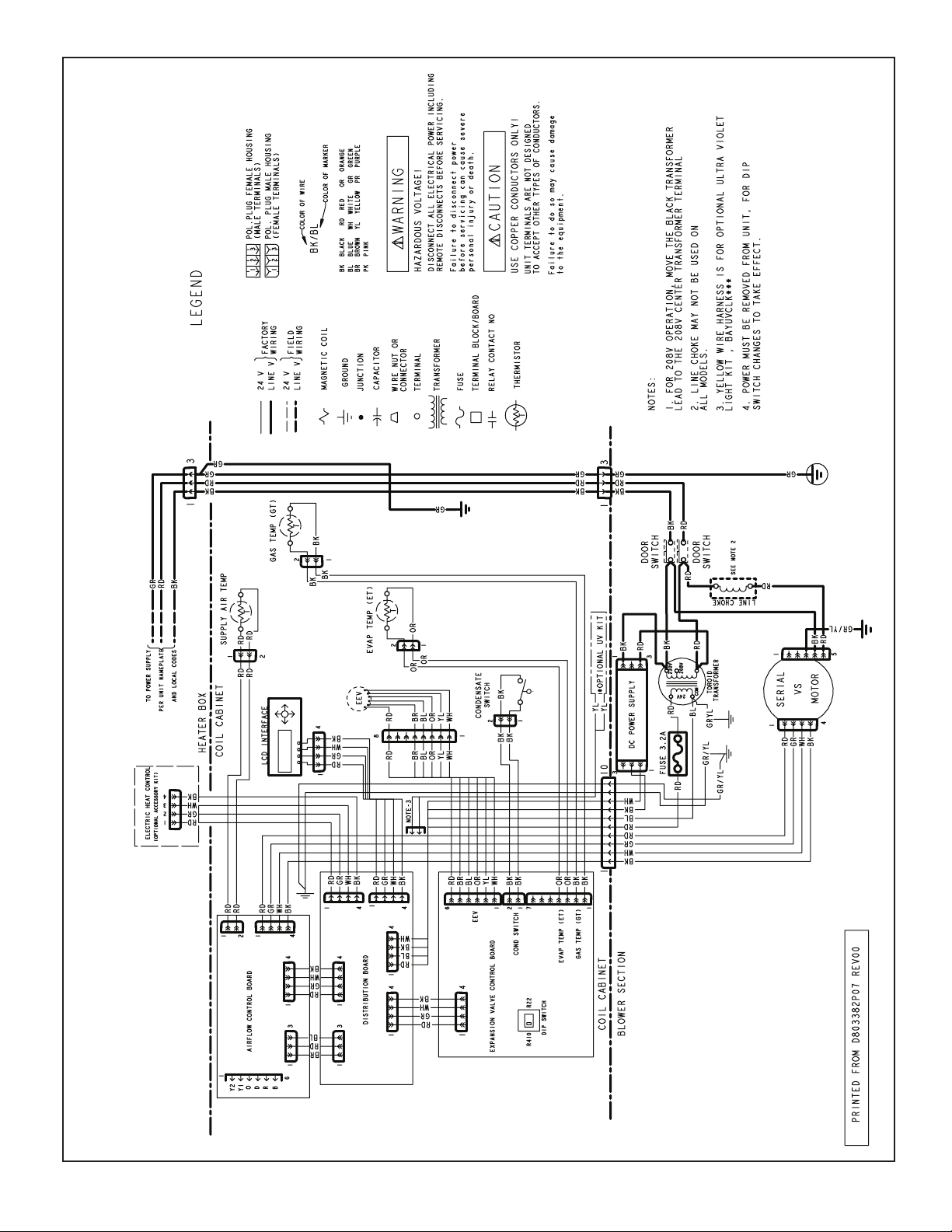
WIRING DIAGRAM FOR *AM8 AIR HANDLERS
5. ET WIRING MAY BE BROWN OR ORANGE.
TAM83
Page 4

SEQUENCE OF OPERATION FOR *AM8
AM8 Sequence of Operation
Abbreviations
• AFC = Airow Control
• EVC = Expansion Valve Control
• EEV = Electronic Expansion Valve
• EHC = Electric Heat Control
• HHC= Hydronic Heat Control
This unit as shipped is ONLY compatible with Trane
and American Standard communicating thermostats and OD units. (24VAC thermostats cannot be
used)
With the addition of a BAYCC24VK01 accessory, this
unit can be compatible with a 24VAC single or
multistage heat pump or air conditioner.
The installing and servicing technician should have an
understanding of the sequence of operation to be
able to properly setup and diagnose functions of
the air handler.
See unit, auxiliary heat, and field wiring diagrams
for additional information.
Continuous Fan
IMPORTANT: If the indoor air exceeds 60% relative
humidity or simply feels uncomfortably humid, it is
recommended that the indoor fan only be used in
the AUTO mode.
1. When a fan request is received from the thermostat, the AFC sends a command to the serial
communicating blower motor to run. Airflow can be
adjusted through the thermostat
2. Humidity Control – When enabled in the thermostat, this feature will disable any blower off delays
and disable continuous fan mode when the humidity is above the dehumidification setpoint. This will
help prevent coil condensation from being evaporated back into the air stream.
Cooling mode
1. When a request for 1st stage cooling is received,
the AFC sends a command to the serial communicating blower motor to run at 1st stage cooling
airflow. (Delay profiles from the thermostat may
change blower motor timing and actual airflow
demand)
TAM84
2. The EVC will receive input from the two temperature sensors and start to control 1st stage superheat.
3. When a request for 2nd stage cooling is received,
the AFC sends a command to the serial communicating blower motor to run at 100 % cooling
airflow.
4. The EVC will now control superheat for 2nd stage.
5. When a request for cooling is removed, the AFC will
turn off the blower motor after any user selected
fan-off delays have expired.
NOTE: Delay profiles from the thermostat may change
blower motor timing and actual airflow demand
Heatpump (compressor only)
1. When a request for 1st stage heat is received, the
AFC sends a command to the serial communicating blower motor to run at 1st stage heating
airflow.
2. Humidifier contacts close
3. The EVC will drive the EEV to the heating position
and refrigerant will flow in the reverse cycle.
4. When a request for 2nd stage mechanical heat is
received, the AFC sends a command to the serial
communicating blower motor to run at 100 % heating airflow.
5. When a request for heatpump is removed, the humidifier contacts open and the AFC will turn off the
blower motor after any user selected fan-off delays
have expired.
NOTE: Delay profiles from the thermostat may change
blower motor timing and actual airflow demand
Electric Heat
1. When a request for electric heat is received, the
AFC communicates to the EHC how much demand for auxiliary heat is being requested
2. The EHC determines the number of elements that
will be used for this request and sends a message
to the AFC for proper airflow. (The EHC determines the amount of heat available per stage by
either factory programming or by the kw jumper
position)
3. The AFC sends a command to the serial communicating blower motor to run proper airflow and close
the blower interlock relay on the EHC.
4. Humidifier contacts close.
5. As demand from the thermostat increases, the EHC
will communicate to the AFC the required airflow
when energizing additional relays.
Page 5

NOTE: The EHC has “lead-lag or rotating” logic built in
that energizes the electric heat relays based upon
cycle counts. To verify operation of all heating
elements, switch thermostat to Emergency Heat
and raise the setpoint of the thermostat at least 5
degrees above the actual room temperature.
Hydronic Heat
1. When the request for hydronic heat is received, the
AFC communicates to the HHC how much auxiliary heat is being requested
2. The HHC will close the K1 relay contacts that enable the boiler or circulating pump to start.
3. The HHC sends a signal to the AFC when the inlet
water temperature reaches 100 degrees for a
maximum of 60 seconds, and then determines the
amount of airflow needed for the heat demand.
4. The AFC sends a command to the serial communicating blower motor to run at the requested CFM.
5. Humidifier contacts close.
6. As demand from the thermostat increases, the
HHC will communicate to the AFC matching airflow requirements.
Defrost
1. The OD unit will initiate defrost and send a message to the AFC.
2. The AFC will communicate to the EVC that the OD
is in defrost and the EVC will start to control the
correct superheat.
3. Electric or hydronic heat will be energized to help
temper the air. (Auxiliary heat options for defrost
can be adjusted through the Display Assembly
Configuration Menu)
Optional Condensate Switch
1. An optional OEM Condensate Switch can be installed within the unit. This switch is only available
through the National Distribution Center or Global
Parts.
2. OEM Condensate Switch contacts are Normally
Open and will close when water level inside the
unit rises. A closed switch will de-energize the OD
unit.
3. The OEM Condensate Switch is only operational
during the cooling mode and is not operational
during heating or defrost modes.
Note: Standard aftermarket condensate switches
(Normally Closed) can be wired in series with the
“External Switch” contacts on the AFC.
Important: The switch action must be selected in the
Configuration Menu section of the Display Assembly to either “Disable Cool” or “Disable All”.
Freeze Protection
1. The EVC control has the ability to sense when the
indoor coil is beginning to ice. If this event should
occur, the AFC will send a message to de-energize
the OD unit.
2. The indoor blower motor will continue running to aid
in defrosting the coil.
3. After 5 minutes, the OD will be turned back on.
(*CONT900 and the 1st release of the *ZONE950
will disable the indoor blower motor and OD unit for
30 minutes)
Unit Test Mode
Unit Test Mode will exit if any demand is given to the
unit.
To enter Unit Test Mode:
1. Set System Switch on comfort control to Off
2. Scroll to the Control Menu on the Display Assembly
3. Scroll down to the Unit Test selection and push the
“Enter” key
Sequence of Unit Test Mode (OD unit is not ener-
gized during the Unit Test Mode)
1. EVC drives the EEV motor to the 1st stage position
for 5 seconds
2. EVC drives the EEV motor to the 2nd stage position
for 5 seconds
3. AFC energizes the blower at 50% and then continues to ramp until it reaches 100% cooling airflow.
4. Humidifier contacts close when the blower starts
5. EHC energizes the circuit relay(s) for 5 seconds
each in 5 second intervals.
6. All relays de-energize and the blower shuts off five
seconds after the last bank of heat is energized.
7. HHC energizes its K1 relay that interfaces with
the boiler system or circulating pump. The blower
continues to run for 30 seconds and then K1 relay
contacts open and the blower shuts off.
If an error occurs during the Unit Test Mode, the Fault
LED will flash a code and continue the test.
TAM85
Page 6
Fault Reporting
Control boards in this unit store active and historical
faults. Each control board will report active faults
continuously and will report the last four faults
stored after a power cycle of the unit. See Fault
Table section for list of fault codes
The active and historical faults can also be accessed
through the Alert Menu in the Display Assembly.
Clearing Fault History
Option 1:
a) Scroll to the Alert Menu in the Display Assembly
b) Scroll to the Alert History section.
c) Scroll to the Clear History selection and push the
Enter key. At the “Are You Sure” question, push the
Enter again.
Option 2:
a) Press and hold the Unit Test Button for 10-12 sec-
onds.
b) Release the Unit Test button and “wait” 5 seconds.
c) Cycle 230VAC power to the unit. (the blower panel
can be removed to achieve this)
CLEAR HISTORY? ↕
YES
Unit Test Button
J6
J11
Airflow Control (AFC)
<ENTER>
24 VAC
TEST
J4
13.8 VDC
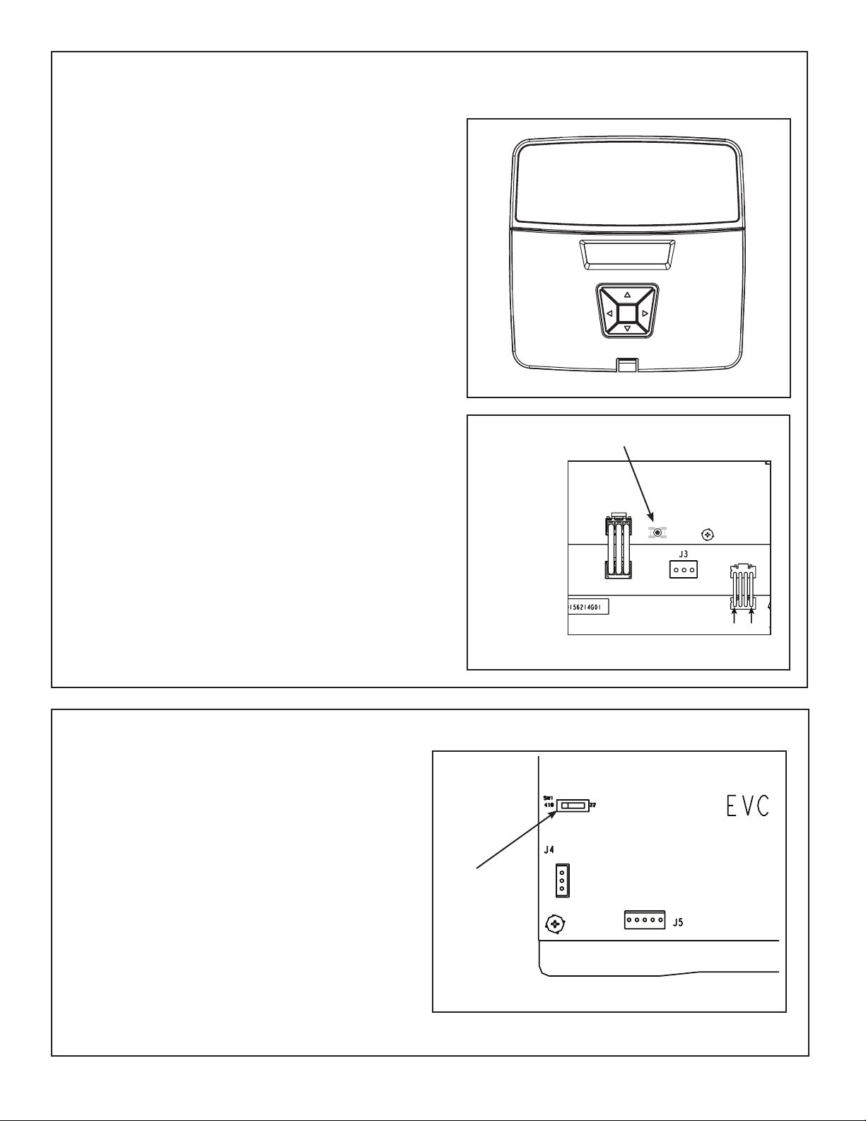
Control Layout - Refrigerant Dip Switch
Refrigerant Switch SW1
• Set the system refrigerant to either R-410A or R-22
using the Refrigerant Switch located on the Expansion Valve Control board (EVC) in the Control Pocket.
• Factory default is R-410A.
• Note: The power must be shut off and then re-applied
in order for the EVC to recognize the change.
TAM86
SW1 Dip
Switch
Electronic Expansion Valve Control (EVC)
Page 7
291
A
A
A
A
A
A
A
A
A
X
134
329
101
76
400
49
425
EXTERNAL STATIC PRESSURE
22
416
CFM
Watts
Powe r
Airflow
290
HEATING
AIRFLOW
CFM/ton
SETTING
434
152
507
129
542
101
69
550
37
532
CFM
Watts
350
CFM/ton
614
197
658
169
679
136
99
680
62
660
CFM
Watts
430
CFM/ton
650
208
690
180
709
145
710
108
69
690
CFM
Watts
450
CFM/ton
527
172
582
147
608
116
82
613
48
593
CFM
Watts
290
CFM/ton
679
218
716
189
734
153
734
115
75
714
CFM
Watts
350
CFM/ton
849
290
874
254
884
213
881
168
862
122
CFM
Watts
430 †
CFM/ton
889
310
912
273
921
231
917
184
899
136
CFM
Watts
450
CFM/ton
707
229
742
198
758
162
757
122
81
738
CFM
Watts
290
CFM/ton
864
297
888
261
898
220
895
174
876
127
CFM
Watts
350
CFM/ton
418
1066
375
1084
326
1089
272
1083
215
1064
CFM
Watts
430
CFM/ton
453
1116
410
1133
360
1139
304
1133
244
1115
CFM
Watts
450
CFM/ton
859
295
883
259
894
217
890
172
871
125
CFM
Watts
290
CFM/ton
401
1041
358
1059
310
1064
257
1058
202
1040
CFM
Watts
350
CFM/ton
470
1138
478
1220
487
1300
432
1302
368
1291
CFM
Watts
430
CFM/ton
462
1128
468
1208
476
1286
483
1360
422
1355
CFM
Watts
450
CFM/ton
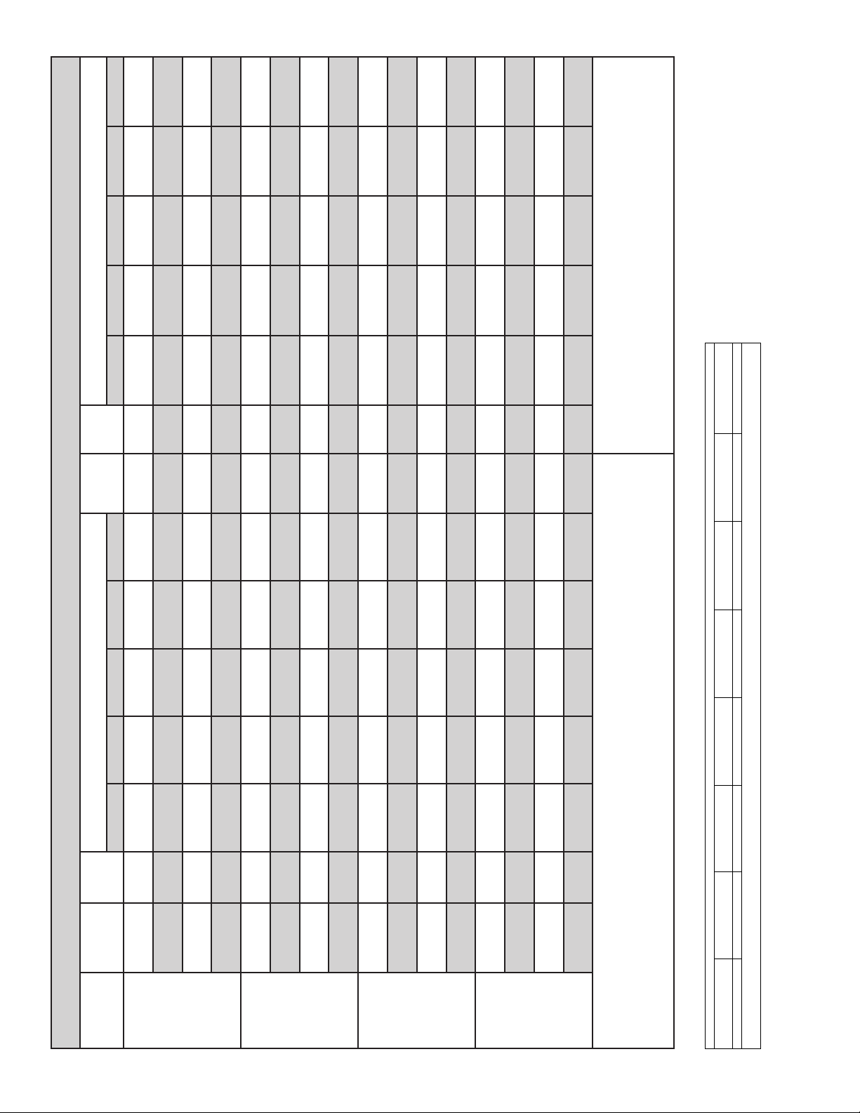
4. Torque mode will reduce airflow when static is above approximately
0.3” water column.
5. All heating modes default to Constant CFM.
6. Cooling airflow values are with wet coil, no filter
BAYEVBC20BK1A
BAYEVCB15LG3A
279 / NA
133 / NA
439 / NA
154 / NA
559 / NA
181 / NA
653 / NA
209 / NA
531 / NA
174 / NA
681 / 383
219 / 145
787 / 561
261 / 183
888 / 689
310 / 225
709 / 473
229 / 162
863 / 680
297 / 221
989 / 821
367 / 280
451 / 354
858 / 674
295 / 219
399 / 307
485 / 408
464 / 464
1120 / 1120
465 / 399
469 / 469
1203 / 1203
339 / NA
102 / NA
514 / NA
131 / NA
612 / 325
155 / 101
694 / 494
181 / 128
588 / 241
149 / 95
720 / 534
190 / 137
818 / 666
228 / 174
913 / 777
274 / 214
745 / 596
199 / 153
890 / 770
262 / 211
1009 / 901
1113 / 961
327 / 270
409 / 345
1132 / 1034
1039 / 877
885 / 764
259 / 209
1058 / 953
1154 / 1046
358 / 297
1205 / 1115
*AM8A0A24 AIRFLOW PERFORMANCE
BAYEVAC10LG3AA BAYEVBC15BK1A
77 / NA
102 / 73
408 / NA
CONSTANT CFM MODE / CONSTANT TORQUE MODE
0.1 0.3 0.5 0.7 0.9 0.1 0.3 0.5 0.7 0.9
EXTERNAL STATIC PRESSURE (Constant CFM / Constant Torque)
Powe r
Airflow
SETTING
AIRFLOW
COOLING
548 / 373
50 / 48
431 / 412
555 / 541
22 / 40
419 / 554
534 / 638
CFM
CFM
Watts
290
350
CFM/ton
123 / 96
636 / 513
70 / 67
88 / 85
639 / 626
37 / 56
52 / 71
617 / 705
CFM
Watts
Watts
400
CFM/ton
CFM/ton
714 / 613
714 / 703
692 / 770
CFM
450
117 / 90
146 / 119
614 / 481
83 / 80
108 / 105
617 / 605
69 / 89
48 / 67
595 / 688
CFM
Watts
Watts
290
CFM/ton
CFM/ton
738 / 643
154 / 127
832 / 751
737 / 727
115 / 112
829 / 821
75 / 96
716 / 792
809 / 877
CFM
CFM
Watts
350
400 †
CFM/ton
190 / 161
924 / 852
231 / 200
147 / 144
920 / 913
185 / 182
103 / 125
900 / 964
136 / 161
CFM
Watts
Watts
450
CFM/ton
CFM/ton
762 / 692
163 / 141
901 / 845
761 / 769
123 / 125
897 / 907
81 / 108
740 / 829
878 / 957
CFM
CFM
Watts
290
350
CFM/ton
220 / 196
281 / 255
1017 / 967
175 / 178
231 / 236
1012 / 1023
127 / 158
178 / 215
993 / 1070
CFM
Watts
Watts
400
CFM/ton
CFM/ton
359 / 330
896 / 840
1139 / 1095
1133 / 1148
1115 / 1193
CFM
450
218 / 194
304 / 312
893 / 902
173 / 176
244 / 290
873 / 953
125 / 156
CFM
Watts
Watts
290
CFM/ton
CFM/ton
310 / 282
1065 / 1018
1059 / 1072
1041 / 1118
CFM
350
415 / 386
1214 / 1175
257 / 264
358 / 368
1210 / 1227
202 / 242
295 / 347
1194 / 1271
CFM
Watts
Watts
400
CFM/ton
CFM/ton
476 / 476
1284 / 1284
483 / 491
1360 / 1373
422 / 476
1355 / 1421
CFM
Watts
450
CFM/ton
SEE AIR HANDLER NAMEPLATE
WITHOUT HEAT PUMP / WITH HP
BAYEVAC10LG1A
BAYEVAC10BK1A
MINIMUM HEATER AIRFLOW CFM - HEATER MATRI
BAYEVAC08LG1A
BAYEVAC08BK1A
BAYEVAC05LG1A
BAYEVAC05BK1A
(TONS)
OUTDOOR
MULTIPLIER
1.5 tons
2 tons †
2.5 tons
3 tons
NOTES:
1. * Models start with "A" or "T"
2. † Factory Setting
3. Status LED will blink once per 100 CFM requested. In torque mode, actual airflow may be lower.
*AM8A0A24V21SAA 638/713 638/900 675/900 600/713 -- -- --
MODEL NO.
AM8A0A24 Minimum Heating Airflow Settings
NOTE: Minimum auxiliary heating airflow is automatically configured by the air
handler model and the auxiliary heater model number. This is not field adjustable.
TAM87
Page 8
A
A
A
A
A
A
A
A
A
X
301
130
97
350
69
393
44
437
EXTERNAL STATIC PRESSURE
21
485
CFM
Watts
Powe r
Airflow
290
HEATING
AIRFLOW
CFM/ton
SETTING
458
146
489
115
85
517
56
545
29
574
CFM
Watts
350
CFM/ton
614
177
636
143
653
108
75
669
42
683
CFM
Watts
430
CFM/ton
649
186
669
151
685
115
80
698
45
709
CFM
Watts
450
CFM/ton
533
160
560
127
95
582
64
604
35
625
CFM
Watts
290
CFM/ton
678
193
696
157
710
120
84
722
49
731
CFM
Watts
350
CFM/ton
853
248
864
205
869
161
871
116
73
868
CFM
Watts
430 †
CFM/ton
895
263
905
219
908
172
908
126
80
902
CFM
Watts
450
CFM/ton
706
201
723
164
736
126
88
746
52
753
CFM
Watts
290
CFM/ton
869
254
879
210
884
165
884
120
75
881
CFM
Watts
350
CFM/ton
342
1078
290
1087
234
1084
176
1074
119
1057
CFM
Watts
430
CFM/ton
366
1128
314
1139
255
1136
194
1125
133
1104
CFM
Watts
450
CFM/ton
863
252
874
208
879
164
880
118
74
877
CFM
Watts
290
CFM/ton
330
1053
279
1061
224
1058
168
1049
112
1034
CFM
Watts
350
CFM/ton
446
1271
398
1300
337
1309
267
1298
193
1271
CFM
Watts
430
CFM/ton
472
1314
427
1350
369
1368
299
1363
221
1338
CFM
Watts
450
CFM/ton
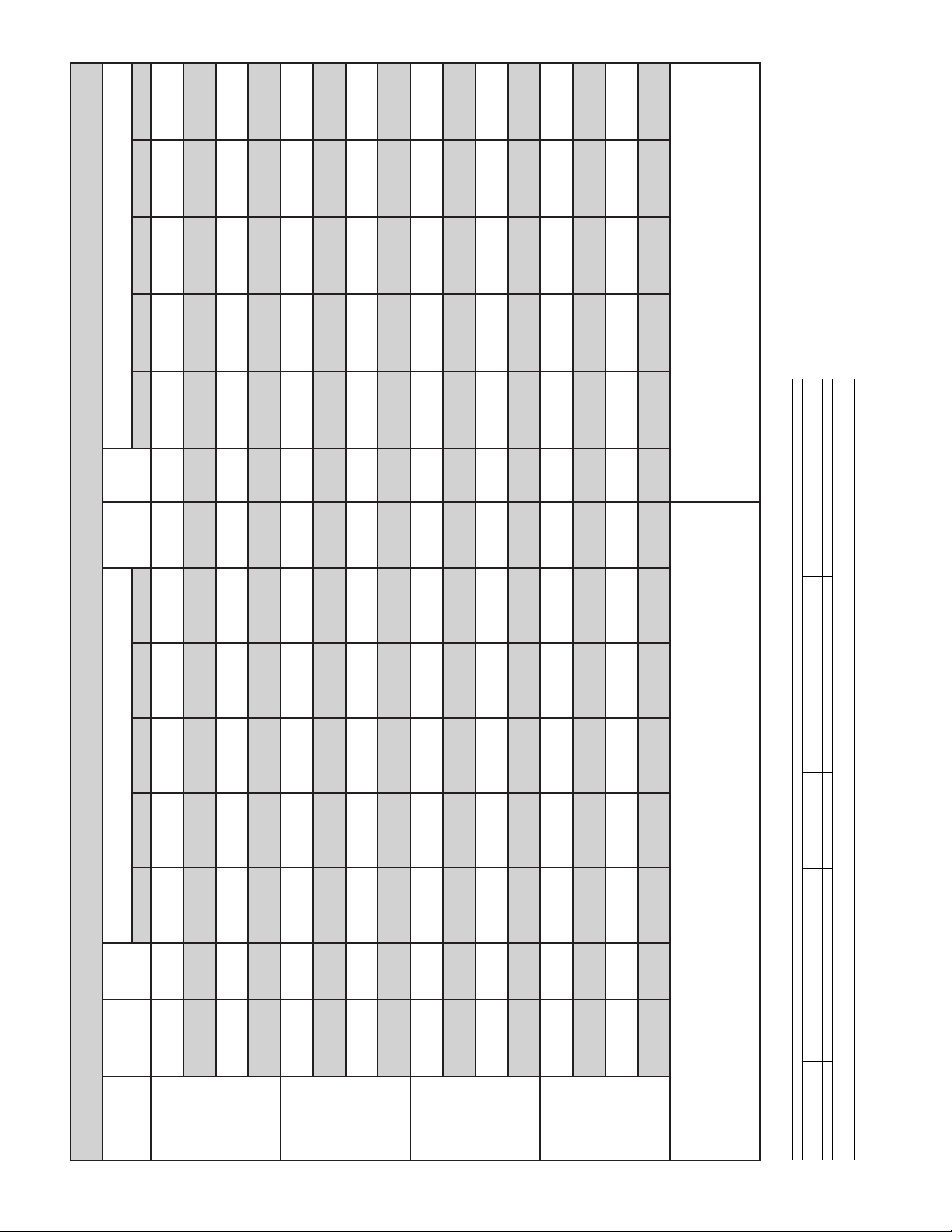
4. Torque mode will reduce airflow when static is above approximately
0.35” water column.
5. All heating modes default to Constant CFM.
6. Cooling airflow values are with wet coil, no filter
BAYEVBC20BK1A
BAYEVCB15LG3A
279 / NA
130 / NA
449 / NA
146 / NA
554 / NA
164 / NA
647 / NA
186 / NA
528 / NA
159 / NA
676 / NA
193 / NA
788 / NA
97 / NA
338 / NA
484 / NA
115 / NA
582 / NA
132 / NA
151 / 91
557 / NA
669 / 231
157 / 94
127 / NA
696 / 299
226 / NA
803 / 463
186 / 115
704 / NA
895 / 394
264 / 138
907 / 621
219 / 141
723 / 409
201 / NA
869 / 401
254 / 139
164 / 105
881 / 625
211 / 142
307 / 177
1001 / 609
1128 / 784
258 / 180
1010 / 777
1141 / 925
366 / 226
863 / 391
252 / 138
314 / 227
875 / 619
209 / 140
330 / 195
1053 / 681
1196 / 886
279 / 197
1063 / 836
1217 / 1016
403 / 261
471 / 347
1311 / 1086
352 / 261
427 / 345
1350 / 1201
*AM8A0B30 AIRFLOW PERFORMANCE
85 / 60
69 / NA
388 / NA
CONSTANT CFM MODE / CONSTANT TORQUE MODE
0.1 0.3 0.5 0.7 0.9 0.1 0.3 0.5 0.7 0.9
EXTERNAL STATIC PRESSURE (Constant CFM / Constant Torque)
Powe r
Airflow
SETTING
AIRFLOW
COOLING
515 / 270
44 / 42
438 / 406
546 / 523
21 / 30
490 / 587
578 / 672
CFM
CFM
Watts
290
350
CFM/ton
99 / 72
605 / 413
56 / 54
67 / 65
626 / 607
29 / 39
37 / 48
646 / 738
CFM
Watts
Watts
400
CFM/ton
CFM/ton
686 / 520
700 / 683
712 / 803
CFM
450
95 / 69
115 / 86
582 / 380
80 / 77
64 / 62
605 / 585
45 / 59
35 / 46
628 / 721
CFM
Watts
Watts
290
CFM/ton
CFM/ton
121 / 91
712 / 552
812 / 668
84 / 81
724 / 708
818 / 803
49 / 62
734 / 824
819 / 908
CFM
CFM
Watts
350
400 †
CFM/ton
145 / 112
911 / 775
173 / 136
103 / 100
910 / 896
126 / 122
63 / 79
80 / 99
904 / 993
CFM
Watts
Watts
450
CFM/ton
CFM/ton
737 / 617
126 / 102
886 / 778
89 / 91
748 / 760
887 / 899
52 / 71
755 / 870
883 / 996
CFM
CFM
Watts
290
350
CFM/ton
165 / 137
206 / 173
1010 / 908
120 / 123
153 / 156
1004 / 1016
75 / 100
101 / 131
991 / 1107
CFM
Watts
Watts
400
CFM/ton
CFM/ton
256 / 218
881 / 773
1139 / 1041
1126 / 1141
1106 / 1226
CFM
450
164 / 136
194 / 199
882 / 894
119 / 121
74 / 99
133 / 172
879 / 992
CFM
Watts
Watts
290
CFM/ton
CFM/ton
224 / 189
1061 / 960
1052 / 1065
1036 / 1153
CFM
350
291 / 251
1217 / 1126
168 / 172
224 / 231
1202 / 1221
113 / 146
158 / 203
1179 / 1304
CFM
Watts
Watts
400
CFM/ton
CFM/ton
370 / 333
1369 / 1302
300 / 311
1365 / 1391
222 / 282
1338 / 1471
CFM
Watts
450
CFM/ton
BAYEVAC10LG3AA BAYEVBC15BK1A
SEE AIR HANDLER NAMEPLATE
WITHOUT HEAT PUMP / WITH HP
BAYEVAC10LG1A
BAYEVAC10BK1A
MINIMUM HEATER AIRFLOW CFM - HEATER MATRI
BAYEVAC08LG1A
BAYEVAC08BK1A
BAYEVAC05LG1A
BAYEVAC05BK1A
(TONS)
OUTDOOR
MULTIPLIER
1.5 tons
2 tons †
2.5 tons
3 tons
NOTES:
1. * Models start with "A" or "T"
2. † Factory Setting
3. Status LED will blink once per 100 CFM requested. In torque mode, actual airflow may be lower.
*AM8A0B30V21SAA 723/808 723/1020 765/1020 680/808 765/1063 850/1105 --
MODEL NO.
AM8A0B30 Minimum Heating Airflow Settings
NOTE: Minimum auxiliary heating airflow is automatically configured by the air
handler model and the auxiliary heater model number. This is not field adjustable.
TAM88
Page 9
A
A
A
A
A
A
A
A
A
X
551
153
551
119
87
557
58
574
EXTERNAL STATIC PRESSURE
31
607
CFM
Watts
Powe r
Airflow
290
HEATING
AIRFLOW
CFM/ton
SETTING
695
185
14
695
697
111
77
705
44
721
CFM
Watts
350
CFM/ton
845
277
844
186
843
144
843
102
62
847
CFM
Watts
420
CFM/ton
908
248
906
204
903
159
900
115
72
900
CFM
Watts
450
CFM/ton
723
192
722
154
724
117
81
730
47
744
CFM
Watts
290
CFM/ton
882
239
880
196
878
153
876
110
68
878
CFM
Watts
350
CFM/ton
307
1062
257
1060
205
1052
152
1046
101
1033
CFM
Watts
420
CFM/ton
340
1138
288
1137
232
1128
175
1116
119
1102
CFM
Watts
450
CFM/ton
877
238
875
195
873
151
871
108
67
873
CFM
Watts
290
CFM/ton
307
1062
257
1060
205
1052
152
1043
101
1033
CFM
Watts
350
CFM/ton
405
1270
351
1277
289
1270
224
1253
158
1231
CFM
Watts
420 †
CFM/ton
448
1348
397
1365
334
1365
264
1349
192
1324
CFM
Watts
450
CFM/ton
292
1026
248
1024
197
1017
141
1005
93
1002
CFM
Watts
290
CFM/ton
388
1236
333
1239
272
1230
209
1215
148
1199
CFM
Watts
350
CFM/ton
476
1394
456
1468
395
1484
327
1480
246
1452
CFM
Watts
420
CFM/ton
469
1383
476
1505
451
1573
385
1584
306
1573
CFM
Watts
450
CFM/ton
4. Torque mode will reduce airflow when static is above approximately
0.35” water column.
5. All heating modes default to Constant CFM.
6. Cooling airflow values are with wet coil, no filter
BAYEVBC20BK1A
BAYEVCB15LG3A
556 / NA
153 / NA
741 / NA
553 / NA
119 / NA
740 / 297
195 / NA
805 / 374
213 / 128
156 / 90
803 / 554
172 / 122
725 / 30
909 / 485
245 / 142
906 / 636
201 / 137
723 / 413
191 / 156
935 / 488
254 / 143
153 / 101
931 / 639
209 / 138
282 / 196
1011 / 731
1138 / 823
234 / 189
1008 / 848
1136 / 933
334 / 222
879 / 480
235 / 141
281 / 215
876 / 632
192 / 136
328 / 196
369 / 278
1123 / 731
1213 / 984
275 / 189
313 / 269
1120 / 848
1212 / 1086
441 / 321
293 / 184
1028 / 687
1352 / 1091
386 / 312
244 / 178
1024 / 808
1364 / 1189
422 / 262
471 / 386
1301 / 942
1386 / 1228
369 / 254
422 / 377
1311 / 1046
1410 / 1324
470 / 443
1379 / 1334
477 / 434
1499 / 1429
*AM8A0C36 AIRFLOW PERFORMANCE
86 / 62
118 / 85
556 / 321
739 / 530
802 / 707
81 / 77
744 / 706
803 / 846
47 / 63
759 / 858
812 / 974
CFM
CFM
Watts
370
400
CFM/ton
132 / 115
92 / 103
54 / 85
Watts
CFM/ton
CONSTANT CFM MODE / CONSTANT TORQUE MODE
57 / 58
573 / 573
0.1 0.3 0.5 0.7 0.9 0.1 0.3 0.5 0.7 0.9
610 / 758
CFM
Powe r
290
SETTING
30 / 47
Watts
CFM/ton
EXTERNAL STATIC PRESSURE (Constant CFM / Constant Torque)
Airflow
AIRFLOW
COOLING
115 / 96
902 / 774
156 / 129
723 / 602
79 / 86
899 / 903
112 / 116
729 / 761
69 / 96
45 / 71
746 / 903
900 / 1024
CFM
CFM
Watts
Watts
450
290
CFM/ton
CFM/ton
927 / 776
163 / 130
1001 / 961
923 / 905
117 / 116
944 / 1070
73 / 97
922 /1026
988 / 1175
CFM
CFM
Watts
370
400
CFM/ton
184 / 177
225 / 202
1127 / 1040
134 / 160
168 / 183
1114 / 1143
86 / 137
112 / 159
1100 / 1243
CFM
Watts
Watts
450
CFM/ton
CFM/ton
872 / 771
148 / 128
1112 / 961
871 / 900
105 / 115
1099 / 1070
64 / 96
874 / 1022
1087 / 1175
CFM
CFM
Watts
290
370 †
CFM/ton
220 / 177
253 / 254
1202 / 1185
163 / 160
192 / 233
1188 / 1280
109 / 137
132 / 207
1170 / 1373
CFM
Watts
Watts
400
CFM/ton
CFM/ton
321 / 296
193 / 167
1016 / 925
1360 / 1284
251 / 275
1344 / 1377
1322 / 1465
CFM
450
138 / 150
1009 / 1037
90 / 128
181 / 247
1006 / 1144
CFM
Watts
Watts
290
CFM/ton
CFM/ton
306 / 239
360 / 361
1306 / 1146
1416 / 1416
238 / 219
289 / 338
1404 /1505
1290 / 1244
170 / 193
213 / 310
1266 / 1338
1378 / 1591
CFM
CFM
Watts
Watts
370
400
CFM/ton
CFM/ton
451 / 419
1572 / 1519
385 / 396
1585 / 1607
307 / 367
1575 / 1691
CFM
Watts
450
CFM/ton
BAYEVAC10LG3AA BAYEVBC15BK1A
SEE AIR HANDLER NAMEPLATE
WITHOUT HEAT PUMP / WITH HP
BAYEVAC10LG1A
BAYEVAC10BK1A
MINIMUM HEATER AIRFLOW CFM - HEATER MATRI
BAYEVAC08LG1A
BAYEVAC08BK1A
BAYEVAC05LG1A
BAYEVAC05BK1A
(TONS)
OUTDOOR
MULTIPLIER
2 tons
2.5 tons
3 tons †
3.5 tons
NOTES:
1. * Models start with "A" or "T"
2. † Factory Setting
3. Status LED will blink once per 100 CFM requested. In torque mode, actual airflow may be lower.
*AM8A0C36V31SAA 876/979 876/1236 927/1236 824/979 927/1288 1030/1339 1236/1442
MODEL NO.
AM8A0C36 Minimum Heating Airflow Settings
NOTE: Minimum auxiliary heating airflow is automatically configured by the air
handler model and the auxiliary heater model number. This is not field adjustable.
TAM89
Page 10

A
A
A
A
A
A
A
A
A
X
734
209
890
738
170
894
740
130
894
90
741
744
51
892
889
EXTERNAL STATIC PRESSURE
259
215
169
123
76
308
1016
160
1019
209
1018
156
1016
103
1006
366
1140
313
1144
256
1142
196
1135
136
1124
885
889
889
887
884
257
214
168
121
75
330
1066
280
1069
227
1067
171
1062
115
1053
403
1212
349
1219
289
1218
225
1209
160
1196
480
1342
430
1366
367
1371
295
1363
220
1347
315
1031
327
1173
214
1033
160
1028
107
1020
417
1236
362
1244
301
1243
236
1234
169
1220
475
1355
458
1411
395
1421
322
1416
244
1440
463
1315
473
1434
474
1545
428
1592
347
1589
383
1174
330
1179
271
1177
209
1169
147
1157
475
1335
458
1411
395
1421
322
1416
244
1400
462
1313
471
1431
474
1545
444
1615
363
1615
452
1297
458
1411
462
1528
453
1629
430
1716
CFM
CFM
Watts
Powe r
Airflow
290
350
HEATING
AIRFLOW
CFM/ton
SETTING
739 / NA
207 / NA
741 / 342
168 / 106
944 / 458
947 / 655
*AM8A0C42 AIRFLOW PERFORMANCE
742 / 591
127 / 102
CONSTANT CFM MODE / CONSTANT TORQUE MODE
0.1 0.3 0.5 0.7 0.9 0.1 0.3 0.5 0.7 0.9
EXTERNAL STATIC PRESSURE (Constant CFM / Constant Torque)
Powe r
Airflow
946 / 823
87 / 94
743 / 764
942 / 956
48 / 77
747 / 905
937 / 1072
CFM
CFM
Watts
CFM
Watts
Watts
400
CFM/ton
CFM/ton
273 / 155
302 / 177
1019 / 586
227 / 155
253 / 178
1022 / 760
179 / 151
201 / 173
1020 / 903
129 / 139
148 / 159
1014 / 1027
80 / 118
95 / 138
1006 / 1136
CFM
Watts
Watts
CFM
CFM
Watts
Watts
450
290
CFM/ton
CFM/ton
357 / 223
889 / 341
1142 / 768
1146 / 911
1143 / 1035
1135 / 1146
1122 / 1247
CFM
254 / 143
303 / 224
892 / 590
209 / 139
245 / 216
891 / 763
163 / 136
185 / 200
889 / 904
116 / 125
70 / 106
125 / 176
885 / 1026
CFM
Watts
Watts
CFM
CFM
Watts
Watts
350
400
CFM/ton
CFM/ton
350 / 217
393 / 256
1128 / 747
1215 / 868
297 / 218
337 / 255
1131 / 893
1221 / 999
240 / 210
276 / 246
1128 / 1019
1218 / 1115
181 / 195
212 / 229
1120 / 1132
1208 / 1220
121 / 171
147 / 204
1108 / 1233
1194 / 1316
CFM
CFM
Watts
Watts
CFM
CFM
Watts
Watts
450
290
CFM/ton
CFM/ton
469 / 334
308 / 182
1034 / 609
1352 / 1061
413 / 331
259 / 183
1037 / 779
1368 / 1175
348 / 320
206 / 178
1034 / 919
1371 / 1279
275 / 300
1361 / 1374
1343 / 1463
CFM
152 / 164
1028 / 1041
99 / 142
200 / 272
1020 / 1149
CFM
Watts
Watts
CFM
CFM
Watts
Watts
350
400 †
CFM/ton
CFM/ton
441 / 303
1304 / 981
1315 / 1110
1314 / 1218
1304 / 1317
1287 / 1408
CFM
480 / 364
1369 / 1124
384 / 301
440 / 361
1415 / 1233
320 / 291
374 / 348
1421 / 1334
250 / 272
300 / 328
1413 / 1427
179 / 245
221 / 299
1395 / 1514
CFM
Watts
Watts
CFM
CFM
Watts
Watts
450
290
CFM/ton
CFM/ton
468 / 477
383 / 249
1174 / 848
1350 / 1326
477 / 472
319 / 248
1181 / 981
1474 / 1425
467 / 458
1576 / 1518
1593 / 1605
1584 / 1687
CFM
259 / 239
1178 / 1098
399 / 435
197 / 222
1169 / 1205
313 / 405
135 / 197
1156 / 1302
CFM
Watts
Watts
CFM
CFM
Watts
Watts
350
400
CFM/ton
CFM/ton
470 / 429
1319 / 1248
1445 / 1350
1496 / 1445
1500 / 1534
1487 / 1618
CFM
463 / 463
1301 / 1301
481 / 425
472 / 472
1423 / 1423
441 / 411
475 / 475
1543 / 1543
369 / 389
443 / 464
1614 / 1646
288 / 359
363 / 433
1616 / 1728
CFM
Watts
Watts
CFM
Watts
4. Torque mode will reduce airflow when static is above approximately
450
CFM/ton
453 / 453
1273 / 1273
460 / 460
1393 / 1393
465 / 465
1514 / 1514
456 / 456
1621 / 1621
432 / 432
1711 / 1711
CFM
Watts
0.35” water column.
5. All heating modes default to Constant CFM.
6. Cooling airflow values are with wet coil, no filter
MINIMUM HEATER AIRFLOW CFM - HEATER MATRI
BAYEVBC20BK1A
BAYEVCB15LG3A
BAYEVAC10LG3AA BAYEVBC15BK1A
SEE AIR HANDLER NAMEPLATE
WITHOUT HEAT PUMP / WITH HP
BAYEVAC10LG1A
BAYEVAC10BK1A
BAYEVAC08LG1A
BAYEVAC08BK1A
COOLING
OUTDOOR
290
SETTING
AIRFLOW
(TONS)
MULTIPLIER
370
CFM/ton
CFM/ton
400
CFM/ton
2.5 tons
450
CFM/ton
290
CFM/ton
370
CFM/ton
400
3 tons
450
CFM/ton
CFM/ton
290
CFM/ton
370 †
CFM/ton
400
450
CFM/ton
3.5 tons †
290
CFM/ton
CFM/ton
370
CFM/ton
400
4 tons
450
CFM/ton
CFM/ton
NOTES:
1. * Models start with "A" or "T"
2. † Factory Setting
3. Status LED will blink once per 100 CFM requested. In torque mode, actual airflow may be lower.
BAYEVAC05LG1A
BAYEVAC05BK1A
*AM8A0C42V31SAA 978/1093 978/1380 1035/1380 920/1093 1035/1438 1150/1495 1380/1610
MODEL NO.
AM8A0C42 Minimum Heating Airflow Settings
NOTE: Minimum auxiliary heating airflow is automatically configured by the air
handler model and the auxiliary heater model number. This is not field adjustable.
TAM810
Page 11

864
A
A
A
A
230
883
197
893
159
900
EXTERNAL STATIC PRESSURE
Airflow
118
72
893
CFM
Watts
Powe r
290
HEATING
AIRFLOW
CFM/ton
SETTING
295
1049
257
1062
213
1070
164
1073
112
1068
CFM
Watts
350
CFM/ton
359
1196
315
1206
266
1212
212
1212
154
1207
CFM
Watts
400
CFM/ton
436
1344
387
1352
331
1354
270
1352
206
1344
CFM
Watts
450
CFM/ton
281
1014
244
1028
202
1037
154
1040
103
1034
CFM
Watts
290
CFM/ton
371
1220
326
1230
276
1236
221
1235
162
1229
CFM
Watts
350
CFM/ton
465
1394
413
1400
356
1403
293
1400
226
1392
CFM
Watts
400
CFM/ton
577
1567
521
1574
457
1576
386
1572
310
1561
CFM
Watts
450
CFM/ton
341
1157
299
1168
251
1174
198
1176
141
1168
CFM
Watts
290
CFM/ton
465
1394
413
1400
356
1403
293
1400
226
1392
CFM
Watts
350
CFM/ton
595
1591
538
1599
474
1601
402
1597
325
1586
CFM
Watts
400 †
CFM/ton
655
1667
665
1766
620
1800
544
1801
459
1794
CFM
Watts
450
CFM/ton
403
1301
355
1309
310
1311
252
1310
189
1302
CFM
Watts
290
CFM/ton
563
1569
505
1575
439
1575
367
1570
290
1557
CFM
Watts
350
CFM/ton
659
1701
663
1794
594
1801
515
1799
428
1789
CFM
Watts
400
CFM/ton
628
1660
634
1757
643
1863
656
1975
605
2018
CFM
Watts
450
CFM/ton
6. If the air handler is applied in downflow or horizontal configurations, the
airflow should not exceed 2000 CFM. Airflow above 2000 CFM could result in
water blow-off.
7. All heating modes default to Constant CFM.
8. Cooling airflow values are with wet coil, no filter
229 /
871 / 445
886 / 622
195 / 137
*AM8A0C48 AIRFLOW PERFORMANCE
896 / 767
900 / 897
0.1 0.3 0.5 0.7 0.9 0.1 0.3 0.5 0.7 0.9
894 / 1018
CFM
Powe r
290
SETTING
157 / 130
114 / 114
69 / 91
Watts
CFM/ton
CONSTANT CFM MODE / CONSTANT TORQUE MODE
EXTERNAL STATIC PRESSURE (Constant CFM / Constant Torque)
Airflow
AIRFLOW
COOLING
292 / 194
354 / 249
1053 / 738
1199 / 926
252 / 192
309 / 244
1065 / 859
1208 / 1029
208 / 180
259 / 229
1072 / 972
1213 / 1128
158 / 160
203 / 206
1073 / 1078
1212 / 1222
106 / 132
145 / 176
1205 /1314
1067 / 1180
CFM
CFM
Watts
Watts
350
400
CFM/ton
CFM/ton
427 / 313
279 / 182
1018 / 690
1346 / 1098
377 / 305
240 / 181
1031 / 817
1353 / 1190
320 / 289
197 / 170
1038 / 934
1355 / 1280
259 / 264
149 / 150
1352 / 1367
1041 / 1044
98 / 123
193 / 232
1343 / 1451
1034 / 1149
CFM
CFM
Watts
Watts
450
290
CFM/ton
CFM/ton
365 / 259
1224 / 955
1232 / 1056
1236 / 1153
1235 / 1246
1228 / 1336
CFM
350
455 / 336
1395 / 1154
319 / 253
402 / 328
1401 / 1244
268 / 238
343 / 311
1403 / 1331
212 / 215
280 / 286
1399 / 1415
212 253
152 / 185
1389 / 1498
CFM
Watts
Watts
400
CFM/ton
CFM/ton
563 / 432
336 / 242
1160 / 905
1568 / 1351
505 / 422
293 / 237
1575 / 1434
1170 / 1010
439 / 404
244 / 223
1575 / 1514
1175 / 1109
367 / 377
191 / 200
1570 / 1592
1175 / 1205
290 / 343
133 / 170
1558 / 1669
1168 / 1298
CFM
CFM
Watts
Watts
450
290
CFM/ton
CFM/ton
455 / 346
580 / 459
1395 / 1177
1593 / 1401
402 / 338
521 / 450
1401 / 1266
1600 / 1483
343 / 321
455 / 431
1403 / 1352
1601 / 1562
280 / 295
382 / 546
1399 / 1436
1595 / 1639
212 / 262
303 / 370
1389 / 1517
1583 / 1714
CFM
CFM
Watts
Watts
400
350 †
CFM/ton
CFM/ton
660 / 601
1698 / 1625
1793 / 1701
1808 / 1775
1800 / 1848
1790 / 1918
CFM
450
404 / 302
1302 / 1071
663 / 592
355 / 294
1309 / 1165
594 / 573
300 / 278
1312 / 1256
515 / 546
241 / 253
1310 / 1344
429 / 511
177 / 222
1301 / 1429
CFM
Watts
Watts
290
CFM/ton
CFM/ton
563 / 444
660 / 601
1568 / 1373
1698 / 1625
505 / 434
663 / 592
1575 / 1455
1793 / 1701
439 / 415
594 / 573
1575 / 1535
1801 / 1775
367 / 389
515 / 546
1570 / 1613
1800 / 1848
290 / 354
429 / 511
1558 / 1688
1790 / 1918
CFM
CFM
Watts
Watts
350
400
CFM/ton
CFM/ton
631 / 631
1651 / 1651
637 / 637
1749 / 1749
645 / 645
1857 / 1857
656 / 656
1973 / 1973
605 / 605
2018 / 2018
CFM
Watts
450
CFM/ton
SEE AIR HANDLER NAMEPLATE
WITHOUT HEAT PUMP / WITH HP
MINIMUM HEATER AIRFLOW CFM - HEATER MATRIX
BAYEVAC10LG1AA BAYEVAC10LG3AA BAYEVBC15BK1AA BAYEVCB15LG3AA BAYEVBC20BK1AA BAYEVCC25BK1AA
BAYEVAC10BK1A
BAYEVAC08LG1AA
BAYEVAC08BK1A
1063/1188 1063/1500 1125/1500 1000/1188 1125/1563 1250/1625 1500/1750 1625/1813
BAYEVAC05LG1AA
BAYEVAC05BK1A
(TONS)
OUTDOOR
MULTIPLIER
TAM811
3 tons
3.5 tons
4 tons †
4.5 tons**
1. * Models start with "A" or "T"
2. † Factory Setting
3. ** Not an actual OD size
4. Status LED will blink once per 100 CFM requested. In torque mode, actual airflow may be lower.
5. Torque mode will reduce airflow when static is above approximately 0.4” water column.
*AM8A0C48V41SA
MODEL NO.
AM8A0C48 Minimum Heating Airflow Settings
NOTE: Minimum auxiliary heating airflow is automatically configured by the air
handler model and the auxiliary heater model number. This is not field adjustable.
Page 12

283
A
1045
247
1063
203
1071
151
1065
EXTERNAL STATIC PRESSURE
95
1039
CFM
Watts
Powe r
Airflow
290
HEATING
AIRFLOW
CFM/ton
SETTING
363
1248
321
1263
270
1270
213
1266
150
1247
CFM
Watts
350
CFM/ton
439
1409
392
1421
337
1426
274
1423
206
1407
CFM
Watts
400
CFM/ton
529
1569
476
1578
416
1582
348
1578
274
1564
CFM
Watts
450
CFM/ton
337
1187
297
1203
248
1210
192
1206
131
1185
CFM
Watts
290
CFM/ton
439
1409
392
1421
337
1426
274
1423
206
1407
CFM
Watts
350
CFM/ton
543
1592
490
1601
428
1604
360
1600
285
1587
CFM
Watts
400
CFM/ton
671
1782
611
1788
543
1788
467
1783
385
1770
CFM
Watts
450
CFM/ton
396
1322
352
1336
300
1342
240
1338
174
1321
CFM
Watts
290
CFM/ton
529
1569
476
1578
416
1582
348
1578
274
1564
CFM
Watts
350
CFM/ton
671
1782
611
1788
543
1788
467
1783
385
1770
CFM
Watts
400 †
CFM/ton
856
2011
788
2014
711
2011
626
2003
534
1989
CFM
Watts
450
CFM/ton
463
1454
415
1466
358
1471
294
1467
224
1452
CFM
Watts
290
CFM/ton
636
1734
578
1740
511
1741
437
1736
357
1723
CFM
Watts
350
CFM/ton
833
1985
766
1988
690
1985
606
1978
515
1964
CFM
Watts
400
CFM/ton
2186
1023
2252
1016
934
2252
842
2245
741
2232
CFM
Watts
450
CFM/ton
6. If the air handler is applied in downflow or horizontal configurations, the
airflow should not exceed 2000 CFM. Airflow above 2000 CFM could result in
water blow-off.
7. All heating modes default to Constant CFM.
8. Cooling airflow values are with wet coil, no filter
283 / 165
1046 / 607
1314 / 945
247 / 175
1066 / 799
1329 / 1068
*AM8A0C60 AIRFLOW PERFORMANCE
203 / 168
EXTERNAL STATIC PRESSURE (Constant CFM / Constant Torque)
Powe r
Airflow
AIRFLOW
1075 / 941
151 / 148
1068 / 1056
0.1 0.3 0.5 0.7 0.9 0.1 0.3 0.5 0.7 0.9
94 / 119
1040 / 1151
CFM
Watts
290
CFM/ton
SETTING
1336 / 1174
1332 / 1264
1312 / 1343
CFM
370
CONSTANT CFM MODE / CONSTANT TORQUE MODE
COOLING
392 / 251
440 / 325
1410 / 1154
349 / 250
393 / 319
1423 / 1256
296 / 235
337 / 301
1429 / 1346
236 / 210
274 / 273
1425 / 1426
171 / 178
206 / 238
1408 / 1496
CFM
Watts
Watts
400
CFM/ton
CFM/ton
529 / 407
337 / 233
1189 / 887
1569 / 1343
477 / 398
1580 / 1432
1584 / 1512
1579 / 1585
1565 / 1650
CFM
450
297 / 234
1206 / 1018
416 / 378
248 / 220
1213 / 1128
348 / 348
192 / 196
1208 / 1223
274 / 312
131 / 164
1186 / 1304
CFM
Watts
Watts
290
CFM/ton
CFM/ton
479 / 334
543 / 430
1482 / 1177
1592 / 1399
430 / 327
490 / 420
1495 / 1277
1602 / 1475
372 / 308
429 / 399
1499 / 1365
1606 / 1554
306 / 280
360 / 369
1495 / 1444
1602 / 1625
235 / 245
285 / 332
1480 / 1514
1587 / 1689
CFM
CFM
Watts
Watts
370
400
CFM/ton
CFM/ton
671 / 546
1782 / 1597
1788 / 1675
1789 / 1747
1784 / 1813
1770 / 1873
CFM
450
397 / 292
1323 / 1069
612 / 534
353 / 288
1338 / 1179
543 / 512
300 / 271
1345 / 1274
468 / 481
240 / 245
1340 / 1358
386 / 443
174 / 211
1322 / 1431
CFM
Watts
Watts
290
CFM/ton
CFM/ton
582 / 417
1653 / 1363
1662 / 1451
1665 / 1530
1660 / 1602
1646 / 1667
CFM
370 †
671 / 546
1781 / 1597
527 / 407
612 / 534
1788 / 1675
463 / 386
543 / 512
1789 / 1747
392 / 357
468 / 481
1784 / 1813
315 / 320
386 / 443
1770 / 1873
CFM
Watts
Watts
400
CFM/ton
CFM/ton
855 / 716
2009 / 1842
2013 / 1913
2012 / 1980
2004 / 2042
1989 2099
CFM
450
463 / 356
1455 / 1231
788 / 703
415 / 348
1468 / 1327
712 / 681
358 / 329
1473 / 1413
627 / 650
294 / 301
1469 / 1489
535 / 612
224 / 265
1452 / 1557
CFM
Watts
Watts
290
CFM/ton
CFM/ton
708 / 515
1831 / 1544
1837 / 1624
1837 / 1698
1831 / 1765
1817 / 1826
CFM
370
832 / 695
1983 / 1814
647 / 503
766 / 682
1987 / 1886
576 / 481
690 / 660
1986 / 1953
499 / 451
607 / 629
1978 / 2015
415 / 451
516 / 590
1964 / 2073
CFM
Watts
Watts
400
CFM/ton
CFM/ton
1024 / 941
2185 / 2104
1015 / 930
2252 / 2171
934 / 908
2252 / 2233
842 / 879
2245 / 2292
741 / 842
2231 / 2347
CFM
Watts
450
CFM/ton
SEE AIR HANDLER NAMEPLATE
WITHOUT HEAT PUMP / WITH HP
MINIMUM HEATER AIRFLOW CFM - HEATER MATRIX
BAYEVAC10LG1AA BAYEVAC10LG3AA BAYEVBC15BK1AA BAYEVCB15LG3AA BAYEVBC20BK1AA BAYEVCC25BK1AA
BAYEVAC10BK1AA
BAYEVAC08LG1AA
BAYEVAC08BK1AA
1063/1188 1063/1500 1125/1500 1000/1188 1125/1563 1250/1625 1500/1750 1625/1813
BAYEVAC05LG1AA
BAYEVAC05BK1AA
(TONS)
OUTDOOR
MULTIPLIER
TAM812
3.5 tons
4 tons
4.5 tons **†
5 tons
1. * Models start with "A" or "T"
2. † Factory Setting
3. ** Not an actual OD size
4. Status LED will blink once per 100 CFM requested. In torque mode, actual airflow may be lower.
5. Torque mode will reduce airflow when static is above approximately 0.4" water column.
*AM8A0C60V51SA
MODEL NO.
AM8A0C60 Minimum Heating Airflow Settings
NOTE: Minimum auxiliary heating airflow is automatically configured by the air
handler model and the auxiliary heater model number. This is not field adjustable.
Page 13

A
A
A
AM8 HEATER ATTRIBUTE DATA
Heater Attribute Data
*AM8A0A24V21SA
240 Volt
Heater Model No.
No Heater 0 - - 3.0** 4 15 - - 3.0** 4 15
BAYEVAC05++1 1 4.80 16400 20.0 29 30 3.60 12300 17.3 25 25
BAYEVAC08++1 1 7.68 26200 32.0 44 45 5.76 19700 27.7 38 40
BAYEVAC10++1 1 9.60 32800 40.0 54 60 7.20 24600 34.6 47 50
BAYEVAC10LG3 1-3 PH 9.60 32800 23.1 32 35 7.20 24600 20.0 28 30
Note: * May be "A" or "T"
Note: ** Motor Amps
Heater Model No.
No Heater 0 - - 3.0** 4 15 - - 3.0** 4 15
BAYEVAC05++1 1 4.80 16400 20.0 29 30 3.60 12300 17.3 25 25
BAYEVAC08++1 1 7.68 26200 32.0 44 45 5.76 19700 27.7 38 40
BAYEVAC10++1 1 9.60 32800 40.0 54 60 7.20 24600 34.6 47 50
BAYEVAC10LG3 1-3 PH 9.60 32800 23.1 32 35 7.20 24600 20.0 28 30
BAYEVBC15LG3 1-3 PH 14.40 42000 34.6 47 50 10.80 36900 30.0 41 45
BAYEVBC15BK1 - Circuit 1 1
BAYEVBC15BK1 - Circuit 2
Note: * May be "A" or "T"
Note: ** Motor Amps
1 MCA and MOP for circuit 1 contains the motor amps
No. of
Circuits
No. of
Circuits
2
Capacity Minimum
kW BTUH kW BTUH
Capacity Heater
kW BTUH kW BTUH
9.60 32800 40.0 54 60 7.20 24600 34.6 47 50
4.80 16400 20.0 25 25 3.60 12300 17.3 22 25
Heater
mps per
Circuit
240 Volt
mps per
Circuit
Circuit
Ampacity
Heater Attribute Data
*AM8A0B30V21SA
Minimum
Circuit
Ampacity
Maximum
Overload
Protection
Maximum
Overload
Protection
Capacity Heater
Capacity
208 Volt
Amps per
Circuit
208 Volt
Heater
Amps per
Circuit
Minimum
Circuit
Ampacity
Minimum
Circuit
Ampacity
Maximum
Overload
Protection
Maximum
Overload
Protection
Heater Attribute Data
*AM8A0C36V31SA
240 Volt 208 Volt
Heater Model No.
No Heater 0 - - 3.0** 4 15 - - 3.0** 4 15
BAYEVAC05++1 1 4.80 16400 20.0 29 30 3.60 12300 17.3 25 25
BAYEVAC08++1 1 7.68 26200 32.0 44 45 5.76 19700 27.7 38 40
BAYEVAC10++1 1 9.60 32800 40.0 54 60 7.20 24600 34.6 47 50
BAYEVAC10LG3 1-3 PH 9.60 32800 23.1 32 35 7.20 24600 20.0 28 30
BAYEVBC15LG3 1-3 PH 14.40 42000 34.6 47 50 10.80 36900 30.0 41 45
BAYEVBC15BK1 - Circuit 1 1
BAYEVBC15BK1 - Circuit 2
BAYEVBC20BK1 - Circuit 1 1
BAYEVBC20BK1 - Circuit 2
Note: * May be "A" or "T"
Note: ** Motor Amps
1 MCA and MOP for circuit 1 contains the motor amps
No. of
Circuits
2
2
Capacity Heater
kW BTUH kW BTUH
9.60 32800 40.0 54 60 7.20 24600 34.6 47 50
4.80 16400 20.0 25 25 3.60 12300 17.3 22 25
9.60 32800 40.0 54 60 7.20 24600 34.6 47 50
9.60 32800 40.0 50 50 7.20 24600 34.6 43 45
mps per
Circuit
Minimum
Circuit
Ampacity
Maximum
Overload
Protection
Capacity Heater
Amps per
Circuit
Minimum
Circuit
Ampacity
Maximum
Overload
Protection
TAM813
Page 14

A
A
A
AM8 HEATER ATTRIBUTE DATA
Heater Attribute Data
*AM8A0C42V31SA
240 Volt
Heater Model No.
No Heater 0 - - 3.0** 4 15 - - 3.0** 4 15
BAYEVAC05++1 1 4.80 16400 20.0 29 30 3.60 12300 17.3 25 25
BAYEVAC08++1 1 7.68 26200 32.0 44 45 5.76 19700 27.7 38 40
BAYEVAC10++1 1 9.60 32800 40.0 54 60 7.20 24600 34.6 47 50
BAYEVAC10LG3 1-3 PH 9.60 32800 23.1 32 35 7.20 24600 20.0 28 30
BAYEVBC15LG3 1-3 PH 14.40 42000 34.6 47 50 10.80 36900 30.0 41 45
BAYEVBC15BK1 - Circuit 1 1
BAYEVBC15BK1 - Circuit 2
BAYEVBC20BK1 - Circuit 1 1
BAYEVBC20BK1 - Circuit 2
Note: * May be "A" or "T"
Note: ** Motor Amps
1 MCA and MOP for circuit 1 contains the motor amps
Heater Model No.
No Heater 0 - - 4.2** 5 15 - - 4.2** 5 15
BAYEVAC05++1 1 4.80 16400 20.0 30 30 3.60 12300 17.3 27 30
BAYEVAC08++1 1 7.68 26200 32.0 45 45 5.76 19700 27.7 40 40
BAYEVAC10++1 1 9.60 32800 40.0 55 60 7.20 24600 34.6 49 50
BAYEVAC10LG3 1-3 PH 9.60 32800 23.1 34 35 7.20 24600 20.0 30 30
BAYEVBC15LG3 1-3 PH 14.40 42000 34.6 48 50 10.80 36900 30.0 42 45
BAYEVBC15BK1 - Circuit 1 1
BAYEVBC15BK1 - Circuit 2
BAYEVBC20BK1 - Circuit 1 1
BAYEVBC20BK1 - Circuit 2
BAYEVCC25BK1 - Circuit 1 1
BAYEVCC25BK1 - Circuit 2
BAYEVCC25BK1 - Circuit 3
Note: * May be "A" or "T"
Note: ** Motor Amps
1 MCA and MOP for circuit 1 contains the motor amps
Heater Model No.
No Heater 0 - - 5.5** 7 15 - - 5.5** 7 15
BAYEVAC05++1 1 4.80 16400 20.0 30 30 3.60 12300 17.3 27 30
BAYEVAC08++1 1 7.68 26200 32.0 45 45 5.76 19700 27.7 40 40
BAYEVAC10++1 1 9.60 32800 40.0 55 60 7.20 24600 34.6 49 50
BAYEVAC10LG3 1-3 PH 9.60 32800 23.1 34 35 7.20 24600 20.0 30 30
BAYEVBC15LG3 1-3 PH 14.40 42000 34.6 48 50 10.80 36900 30.0 42 45
BAYEVBC15BK1 - Circuit 1 1
BAYEVBC15BK1 - Circuit 2
BAYEVBC20BK1 - Circuit 1 1
BAYEVBC20BK1 - Circuit 2
BAYEVCC25BK1 - Circuit 1 1
BAYEVCC25BK1 - Circuit 2
BAYEVCC25BK1 - Circuit 3
Note: * May be "A" or "T"
Note: ** Motor Amps
1 MCA and MOP for circuit 1 contains the motor amps
No. of
Circuits
2
2
No. of
Circuits
2
2
3
No. of
Circuits
2
2
3
Capacity Heater
kW BTUH kW BTUH
9.60 32800 40.0 54 60 7.20 24600 34.6 47 50
4.80 16400 20.0 25 25 3.60 12300 17.3 22 25
9.60 32800 40.0 54 60 7.20 24600 34.6 47 50
9.60 32800 40.0 50 50 7.20 24600 34.6 43 45
Capacity Heater
kW BTUH kW BTUH
9.60 32800 40.0 55 60 7.20 24600 34.6 49 50
4.80 16400 20.0 25 25 3.60 12300 17.3 22 25
9.60 32800 40.0 55 60 7.20 24600 34.6 49 50
9.60 32800 40.0 50 50 7.20 24600 34.6 43 45
9.60 32800 40.0 55 60 7.20 24600 34.6 49 50
9.60 32800 40.0 50 50 7.20 24600 34.6 43 45
4.80 16400 20.0 25 25 3.60 12300 17.3 22 25
Minimum
mps per
Circuit
Ampacity
Heater Attribute Data
*AM8A0C48V41SA
240 Volt 208 Volt
Minimum
mps per
Circuit
Ampacity
Heater Attribute Data
*AM8A0C60V51SA
240 Volt 208 Volt
Minimum
mps per
Circuit
Ampacity
Circuit
Circuit
Circuit
Maximum
Overload
Protection
Maximum
Overload
Protection
Maximum
Overload
Protection
Capacity Heater
Capacity Heater
Capacity Heater
Notes:
1. See Product Data or Air Handler nameplate for approved combinations of Air Handlers and Heaters
2. Heater model numbers may have additional suffix digits.
TAM814
208 Volt
Amps per
Circuit
Amps per
Circuit
Amps per
Circuit
Minimum
Circuit
Ampacity
Minimum
Circuit
Ampacity
Minimum
Circuit
Ampacity
Maximum
Overload
Protection
Maximum
Overload
Protection
Maximum
Overload
Protection
Page 15

WHEEL
BLOWER HOUSING
BELLY BAND
MOTOR
A
A is determined per chart
Wheel is centered in
Blower Housing
SUBCOOLING ADJUSTMENT
Indoor Unit Model No. Outdoor Unit Model No. Subcooling
*AM8A0B30V21CA 4A6H6024E, 4TWX6024E 9°
*AM8A0C36V31CA 4A6H6036E, 4TWX6036E 10°
*AM8A0C48V41CA 4A6H6048E, 4TWX6048E 8°
*AM8A0B30V21CA 4A7A6024E, 4TTX6024E 8°
*AM8A0C36V31CA 4A7A6036E, 4TTX6036E 8°
*AM8A0C48V41CA 4A7A6048E, 4TTX6048E 8°
*AM8A0B30V21CA 4TWZ0024A, 4A6Z0024A 9°
*AM8A0C36V31CA 4TWZ0036A, 4A6Z0036A 10°
*AM8A0C48V41CA 4TWZ0048A, 4A6Z0048A 12°
*AM8A0B30V21CA 4TTZ0024A, 4A7Z0024A 9°
*AM8A0C36V31CA 4TTZ0036A, 4A7Z0036A 11°
*AM8A0C48V41CA 4TTZ0048A, 4A7Z0048A 13°
* May be “A” or “T”
All other matches must be charged per the nameplate charging instructions.
DISTANCE FROM BELLY BAND TO SHAFT FACE OF MOTOR FOR MINIMUM VIBRATION
MODEL DIM "A"
*AM8A0A24V21CA 2-3/8
*AM8A0B30V21CA 2-3/8
*AM8A0C36V31CA 2-3/8
*AM8A0C42V31CA 2-3/8
*AM8A0C48V41CA 2-3/8
*AM8A0C60V51CA 2-3/8
* May be "A" or" T"
TAM815
Page 16

Air Handler Control Panel - LEDs
Airflow Control (AFC)
J8
13.8 VDC
From DC Power Supply
24 VAC
From Transformer
J10
HUM
J7 - Motor
BM LED
J8
J2
J9 - EHC/HHC
13.8 VDC
13.8 VDC
Unit Test
TEST
J6
J5
J4
24 VAC
J11
J1
13.8 VDC
To EEV Stator
J2
J10 - Display Assembly
Distribution
Board
To Internal
J6
Condensate
Switch (Optional)
ET Sensor
J3
GT Sensor
See Table
Electronic Expansion Valve Control (EVC)
COMM LED
UNIT
BM
B
D
R
O
Y1
Y2
WIRE
TIE
STATUS
LED
STATUS
COMM
UNIT
LED
FAULT
FAULT
LED
TAM816
STATUS
LED
UNIT
STATUS
UNIT
LED
FAULT
FAULT
LED
OPEN
SW1
R410A / R22
TEST
CLOSE
OPEN
TEST
CLOSE
J4
Page 17

AFC BM (Bit Master) LED (GREEN LED)
Airflow Control (AFC)
J7 - Motor
J10
TEST
Unit Test
24 VAC
J4
J8
J9 - EHC/HHC
13.8 VDC
J8
J2
13.8 VDC
r
AFC BM LED
Solid ON
Normal operation
Description
AFC COMM LED (AMBER LED)
WIRE
TIE
HUM
AFC COMM LED
Device count
Number of communicating devices*
Description
* Examples: communicating thermostat, communicating air cleaner, etc.
AFC STATUS CODES (GREEN LED)
AFC STATUS LED
ON SOLID Power up and during last 4 fault history sequence
1 Flash (per second) Stand-by or idle
Multiple Flash CFM demand - 1 flash per 100 cfm
Description
AFC UNIT LED (BLUE LED)
UnitLED
1Flash
Rapid
SOLIDON
Off
Normal(1flashevery4seconds)
CommunicationBusyError(2flashespersecond)
CommunicationscannotbeestablishedwiththeAFC
NoPower
Description
STATUS
LED
UNIT
LED
FAULT
LED
Y2
Y1
O
D
R
B
BM
COMM
STATUS
UNIT
FAULT
BM LED
COMM LED
J6
AFC FAULT CODES (RED LED)
AFC Fault
LED Description
OFF No Fault
SolidOn Internal control failure
1 24VAC fuse blown
2
3
4 Blower communication error (Status LED will be ON solid)
5
6
8
11
12
NOTES:
TAM817
PM Data Corrupt or Missing / Motor Mismatch
Communication error 3
Internal communication error (refer to Unit LED on EVC, EHC, HHC) (1)(2)
Indoor coil air sensor error
Twinning erro
EVC has detected a fault condition (refer to Fault LED on EVC)
EHC / HHC has detected a fault condition (refer to Fault LED on EHC / HHC)
1) If Unit LED on AFC is flashing 2 times/second, AFC is causing the error.
2) Unit LED on suspect control will flash 2 times/second on the suspect control.
3) Error is associated with the ComfortLink
All LED's will be off if power is not applied.
TM
II or AccuLinkTM communcating bus.
Page 18

EVC STATUS CODES (GREEN LED)
A
A
y
EVC STATUS LED (Non Heat Pump Systems)
Flash
1 Cool mode selected / No active call
2 Active call for 1st stage cooling
3
NOTE:
ctive call for 2nd stage cooling (1)
(1) Single stage OD systems will report 2nd stage flash codes
EVC STATUS LED (Heat Pump Systems)
Flash
1 Cool mode selected / No active call
2 Active call for 1st stage cooling or defrost
3 Active call for 2nd stage cooling or defrost (1)
4 Heat mode selected or Thermostat system switch off
5 Active call for 1st stage heating
6
NOTE:
ctive call for 2nd stage heating (1)
(1) Single stage OD systems will report 2nd stage flash codes
EVC UNIT LED (BLUE LED)
STATUS
LED
UNIT
LED
FAULT
LED
SW1
R410A / R22
J4
OPEN
TEST
CLOSE
J11
STATUS
UNIT
FAULT
EVC
OPEN
TEST
CLOSE
UnitLED
1Flash
Rapid
SOLIDON
Off
Normal(1flashevery4seconds)
CommunicationBusyError(2flashespersecond)
CommunicationscannotbeestablishedwiththeAFC
NoPower
Description
EVC FAULT CODES (RED LED)
EVC
Fault LED Description
OFF Standb
1 Stepper Motor or wiring harness has an open circuit or intermittent short
Control has detected an internal failure (Verify EEV motor resistance and harness wiring)
2
Saturated Gas Sensor input out of range (Verify resistance, 5VDC output from control)
3
4 Evaporator Gas Sensor input out of range (Verify resistance, 5VDC output from control) (1)
Stepper Motor Coil is shorted
5
Valve is not responding to a change in position. (Possible stuck valve)
6
High superheat (Low charge or restriction)
7
Low superheat (Check airflow, possible stuck valve)
10
Condensate drain switch activated for 100 seconds (Check condensate switch and drain)
11
Indoor frost protection activated (Check refrigerant charge and airflow)
13
Internal communication fault (All operation is terminated) (Cycle power & check wire terminations)
14
Configuration fault (All operation is terminated) (Cycle power & check if PM error is present)
15
Outdoor status fault (All operation is terminated)
16
(2)
(3)
(2)
(1)
(2)
NOTES:
1) EEV will try to go to a safe position, cooling attempt allowed
2) K1 relay opens on EVC, Yo disabled
3) Cooling attempt allowed, 5 consecutive Y calls with same condition disables Yo
TAM818
Page 19

PARK
T8
T7
+5V
GND
25KW
R63
R62
R19
T11
T9
R53
R52
R48
R47
D20
D1
9
C11
C9
P3
R43
R39
R38
R33
R32
D6
D5
C
10
C6
C4
C8
C2
K6
U3
R20 R25
U8 U9
T10
T12
R17
R16
R23
R22
R21
R24
K5
D21
R67
R68
D24
D25
EHC UNIT LED (BLUE LED)
EHC Fault
UnitLED
1Flash
Rapid
SOLIDON
Off
Normal(1flashevery4seconds)
CommunicationBusyError(2flashespersecond)
CommunicationscannotbeestablishedwiththeAFC
NoPower
Description
EHC STATUS CODES (GREEN LED)
EHC STATUS LED
1
2
3
4
5 5 heater relays energized
NOTES
1 heater relay energized or stand by (see note)
2 heater relays energized
3 heater relays energized
4 heater relays energized
Standby mode STATUS LED will flash 1 time per second
On a call for heat, STATUS LED will flash per the table above every 4 seconds
EHC FAULT CODES (RED LED)
Description
TAM819
LED Description
OFF Nofault
1 Internalcommunicationerror
2 Heatrelaystuckopen
3 Heatrelaystuckclosed
4 Non‐cyclinglimit(NTCO)orelementopen
5 Cyclinglimit(CTCO)open
6
Configurationerror
(1)
8 Blowerinterlockrelaystuckopenorstuckclosed
NOTES:
1) Confirm heater model and kw jumper match
UNIT
LED
STATUS
LED
FAULT
LED
T4
T2
T1
K1
R3
R44
R4
D1
U5
R5
TRANEU.S.INC.
R28
D12
UNIT
D9
R26
D10
D7
STATUS
R27
D11
D8
FAULT
C12
T3
K2
R1
R8
R9
R2
D2
+13.8V
D23
9
D16
2
R
D17
D22
R30
D14
D15
P1
AUX
PGC
R6
R45
R7
U6
D3
R10
C1
U1
U2
69
R31
R
JP1
6
6
R
C13
1
R41
R
D
D
G
D
CL
P
V
VSS
M
T6
T5
K3
R46
R13
R14
R40
R36
C7
X1
R59
R50
R57
C5
R34
R35
K4
R11
R18
R12
U7
D4
R15
8KW
15KW
10KW
5KW
20KW
R49
R37
4
5
R6
R6
1
U4
4
0
6
R
R56R55R5
R6
R73
R58
R70
C3
OV1
51
R72
R
M
1
R7
P2
B
ND
AA
A
G
T
13.8V
AT
D
DA
Page 20

HHC FAULT CODES (RED LED)
HHC
Fault LED Description
OFF Nofault
1 Internalcommunicationerror
2 Watertempisat38Forlower
3 Watertempsensorisshorted
4 Watertempsensorisopen
5
Configurationerror
6 Heatdemanderror
(1)
NOTES:
1) Confirm heater model and dip switch configuration
HHC STATUS CODES (GREEN LED)
HHC STATUS LED
1 per second
2 per second
Standby or idle (see note)
Heating demand is present
HHC UNIT LED (BLUE LED)
UnitLED
1Flash
Rapid
SOLIDON
Off NoPower
Normal(1flashevery4seconds)
CommunicationBusyError(2flashespersecond)
CommunicationscannotbeestablishedwiththeAFC
Description
Description
13.8V
DATAA
DATAB
GND
MOV1
13.8VDC
D13
K1
P4
1
TAM820
D11
C1
R41
.
P1
R40
R44
R45
5
R2
3
2
R24
R
R22
C13
R28
R27
U2
R29
R26
30
R
32
R
1
3
Q1
R
5
1
R
R14
R16
GND
C9
TRANEU.S.INC.
C14
U3
C2
C3
0
R2
C10
R34
C8
R9
R11
R1
C15
C4
+5V
U1
R37
1
X
R13
R33
R48
R47
R46
39
R
C5
12
R
.
MCLR
R8
VDD
D8
D7
VSS
PGD
PGC
AUX
D9
10
P3
R
D10
Pb
D6
R19
D3
FAULT
8
R1
D5
D2
STATUS
R42
D4
R17
D1
R6
UNIT
D17
D15
D18
D14
R7
16
D
SW1
1
C17
D12
P6
R5
R4
R43
R35
C11
C12
C16
R36
R2
C6
P5
C7
R3
FAU LT
STATUS
UNIT
Page 21

LED Codes - The three LED lights below appear on
the CCM control board. (BAYCC24VK01A)
CCM COM LED (AMBER LED)
CCM COMM LED
Device count
Number of communicating devices*
Description
* Examples: communicating thermostat,
communicating air cleaner, etc.
CCM STATUS LED (GREEN LED)
CCM STATUS LED
1 Flash per second
1 Flash per 4 seconds
2 Flash per 4 seconds
Idle / Standby
1st Stage
2nd Stage
Description
CCM FAULT LED (RED LED)
CCM FAULT LED
3 Flash
Communication Error
Description
COM
STATUS
FAU LT
TRANEU.S.INC
H1
R1
K2
K2
R2
K3
K3
R26
K4
K4
VR10
K1
K1
H3
H3
TRANEU.S.INC
7
C19
43
R3
CR28
1
1
O
VR7
VR8
C21
GNDNCUV
J3
R
D
D
1
1
4
4
J1
R
2
4
CR
R51
C
6
4
R
R48
C41
5
C32
LED
LED4
LED3
R73
C44
R49
FAULT
C43
C83
CR50
OFF
HP
ZR3
COM
R45
R82
83
R
STATUS
R81
BARCODE
BARCODE
U2
U1
U1
1
71
R
R89
R88
CR53
CR10
52
R
S1
C
R3
OFF
HP
1
1
1
1
L1
+
C27
1
1
D
183
TP
R32
RN1
C30
ZR7
TP181
C79
1
X
C77
R74
R158
R164
Q14
ON
R34
AC
R87
C20
4
2 STG
U4
R15
2CMP
Y1
Y1
Y2
Y2
CR43
C1
CR44
C2
P1
1MODE
C42
R47
R41
R40
C45
1
H2
H2
R
B
J2
C17
4
VR
R55
R61
CR26
R62
R60
65
R59
R
6
6
R
6
U
R57
R67
D19
C26
VR1
C36
+
+
C35
BEL
BEL
A
A
L
L
CR3
127
125
Q10
R
R
C78
6
R
C
8
7
Q11
D4
R
CR4
157
R
CR9
R98
126
R
2
R1
R
C
C
C29
R118
8
15
Q9
Q8
R1
R10
CR5
TP109
C31
Q7
H4
H4
R106
R119
TAM821
Page 22

ALERT CODES FOR *AM8
d
r
y
t
y
y
r
e
t
y
y
r
e
)
(Op
)
(Op
)
)
w
,
n
T
ge,
n
g
p
p
n
,p
y
y)
y)
p
d
p
y)
d
d
AFC
EVC
EHC
Alert
Code
18 Control failure CNTRL FLT ERR18 ERR 18.0 Critical
19 Twinning fault TWIN ERR ERR19 ERR 19.0 Information 8 Air handler twinning error
52 Indoor air sensor error ICAS OPEN N/A N/A Information 6 Indoor air sensor is open Sensor open, unplugged, wiring harness
52 Indoor air sensor error ICAS SHORT N/A N/A Information
90 Communication busy fault SYS COM CRC N/A N/A Information 3 Excessive communication errors R & B to thermostat reversed polarity
91 Communication inactive fault
91 Communication inactive fault NO SYS CLK ERR91 ERR 91.03 Critical
92 Fuse failure CHECK FUSE N/A N/A Critical
104 Heater relay fault
104 Heater relay fault ALL RLY OPEN ERR104 ERR 104.02 Critical 12 2 All heater relay stuck open error Heater relay failure
104 Heater relay fault
105 Heater interlock rela
105 Heater interlock relay faul
106 External shutdown fault EXT SW OPEN ERR106 ERR 106.0 User Display 1 External shutdown input open error External float switch, other device open
114 PM bad or missing fault PM DATA ERR N/A N/A Information 2 PM data corrupt (Operation allowed) PM error
114 ID motor error ID MTR ERR ERR114 ERR 114.02 User Display 2
114 PM bad or missing fault PM MISSING ERR114 ERR 114.03 Critical 2
114 PM bad or missing fault PM UNIT ERR N/A N/A Information 2
114 PM bad or missing fault PM MEM ERR ERR114 ERR 114.05 Critical 2
114 PM bad or missing fault PM MISSING ERR114 ERR 114.06 Critical 2
114 ID motor error MTR PWR HI ERR114 ERR 114.07 User Display 2
123 Demand configuration fault EH CONFIG ERR123 ERR 123.0 User Display 12 6 Electric heat configuration rrror
152 Heater element fault
153 Thermal limit switch fault EH CTCO TRIP ERR153 ERR 153.0 User Display 12 5 Cycling thermal cut-out trip has occurred Low airflow, dirty coil/filter
154 EH airflow limit fault EH OFF/NO AF ERR154 ERR 154.0 Critical 12 7
154 EH airflow limit fault EH LIM/NO AF ERR154 ERR 154.1 User Display 12 7
155
155
156 System low on charge fault
157 Condensate fault
158 Coil freeze fault ID COIL FRST ERR158 ERR 158.0 User Display 11 13 Indoor coil freeze condition detected
159 Unit Bus fault
159 Unit Bus fault
159 Unit Bus fault
159 Unit Bus fault
159 Unit Bus fault
160 Indoor EEV control configuration error CONFIG FLT ERR160 ERR 160.0 User Display 11 15
161 Evaporator temperature sensor fault ET SEN ERR ERR161 ERR 161.0 User Display 11 3
161 Gas temperature sensor fault GT SEN ERR ERR161 ERR 161.01 User Display 11 4
163 Indoor EEV control fault EEV CNTL FLT ERR163 ERR 163.0 User Display 11 2
164 Indoor EEV fault
164 Indoor electronic expansionvValve fault
166 Superheat is flooding fault SYSTEM4 ERR ERR166 ERR 166.0 User Display 11 10 System 4 - Low superheat
167
168
169
170
171 Communication inactive fault
172 Display Assembly stuck key KEY FAULT ERR172 ERR 172.0 User Display Display Assembly has a stuck key Faulty Display Assembly
173
173
Alert Group
faul
Indoor electronic expansion valve
motor fault
Indoor electronic expansion valve
motor fault
Indoor electronic expansion valve
control is not controlling because
outdoor status is unknow
Indoor heat demand is not available to
hydronic heat control
Hydronic heat control configuration
fault
Hydronic heat control freeze condition
detected
Open coil freeze sensor (hydronic heat
onl
Shorted coil freeze sensor (hydronic
heat onl
Notes:
1. * AFC STATUS LED will be solid ON during this fault•
2. COMM LED (amber) will flash the number of communicating devices connecte
3. BM LED should be ON Solid when power is applied
4. STATUS LED will flash once per second in Idle mode.
Once a thermostat demand is received, it will flash 1 time/100 CFM requested
5. UNIT LED (blue) will flash once every four seconds when communications are norma
Display
ERR
EH RLY
OPEN#
EK RLY
WELD#
OP#
ERR
FL
ERR
ERR
ERR
ERR
ERR
ERR
ERR
ERR
SHORT
A/TCONT900 A/TZONE 950
ERR91 ERR 91.02 Critical 3 Loss of Heat/Cool demand message
ERR104 ERR 104.0 User Display 12 2 Heater relay stuck open error Heater relay failure
ERR104 ERR 104.01 Critical 12 3 Heater Relay Stuck Closed Error
ERR152 ERR 152.0 User Display 12 4 Heater element open Low airflow, dirty coil/filter
ERR156 ERR 156.0 User Display 11 7 System 1 - High superheat
ERR157 ERR 157.0 Critical 11 11 Condensate overflow condition detected Condensate line clogged
ERR159 ERR 159.0 Critical 5 14 1 1 AFC communication error
ERR159 ERR 159.01 User Display 5 1 EHC communication error
ERR159 ERR 159.02 User Display 5 1 HHC communication error
ERR159 ERR 159.03 User Display 5 14 EVC communication error
ERR159 ERR 159.04 Information 5 Display Assembly communication error
ERR164 ERR 164.0 User Display 11 6
ERR164 ERR 164.01 User Display 11 6
ERR171 ERR 171.0 Critical 4* Blower Communication is not detected Faulty wiring harness, VS motor
ERR173 ERR 173.0 User Display 12 3
Assembly Text
SYS COMM
BL INTLK OP ERR105 ERR 105.0 User Displa
BL INTLK CL ERR105 ERR 105.01 User Displa
EH ELMNT
EEV MTR ERR ERR155 ERR 155.0 User Display 11 5
EEV MTR ERR ERR155 ERR 155.01 User Display 11 1
SYSTEM1
CONDESAT
AFC COMM
EHC COMM
HHC COMM
EVC COMM
CDA COMM
EEV CLSE
EEV OPEN
OD DATA MISS ERR167 ERR 167.0 User Display 11 16 OD status unknown to EVC
HH FAULT ERR168 ERR 168.0 User Display 12 6
HH CONFIG ERR169 ERR 169.0 User Display 12 5
HH FRZ DET ERR170 ERR 170.0 User Display 12 2 Hydronic heat coil freeze detected
BLW COMM
HH FRZ OPEN ERR173 ERR 173.01 User Display 12 4
HH FRZ
Notification
Level
Fault
Fault
Code
Code
ON
6
3
1*
12 8
12 8
TAM822
Fault
Code
HHC
Fault
Code
Alert Description Possible Cause
Internal Control Error Control fault, replace AFC
Indoor air sensor is shorte
Loss of Bit Master Control fault, replace AFC
24V fuse open error 24VAC circuit short
Interlock Rela
Interlock Rela
Motor HP is < than PM value (Operation
PM missing with good local copy
Bad data in PM with good local copy
Bad data in PM with no local copy
PM missing with no local copy (Operation
Motor HP is > than PM value (Operation
Electric heat control locked out because of
Electric heat control is under restricted
operation because of insufficient airflow
EEV motor fault has been detected for 8
consecutive times and valve is locked out
EEV electric motor current indicates open
Configuration group index or evap
Indoor coil temperature sensor reading is
out of range, indicates open or short
Indoor coil temperature sensor reading is
out of range, indicates open or short
EEV electric motor drive or feedback or 12
EEV migrated to 'Close' position but
superheat is not at the desired set point,
valve is not responding to a change in
EEV migrated to 'Open' position but
superheat is not at the desired set point,
valve is not responding to a change in
Hydronic Heat is not controlling because
Indoor heat demand is not received
Hydronic heat capacity is unknown to
Hydronic coil freeze inlet temperature
Hydronic coil freeze inlet temperature
Stuck Open Erro
Stuck Closed Erro
not allowed)
(Operation allowed
eration allowed
eration allowed
not allowed
allowed)
insufficient airflo
or short
temperature sensor type are not
sensor o
sensor short condition detecte
ured
confi
V failure detected
osition
osition
dronic heat control
h
en condition detecte
More than one ID unit connected on the
communicating bus is not allowed
Sensor shorted, wiring harness
Open / Shorted data line / CCM
communication erro
Heater relay failure, open element, open
non cycling limit switch
Blower interlock relay failur
Blower interlock relay failur
Incorrect VS motor or PM installed
PM error
PM error
PM error
PM error
Incorrect VS motor or PM installed
KW jumper position on PARK
(replacement control only)
EHC locked out
Heater-Air handler mismatch
Faulty EEV motor / wiring harness
Faulty EEV motor / wiring harness
System low on charge, liquid line
ET/GT sensor calibratio
restriction
Low / incorrect airflow, low refirgerant
ET sensor calibratio
char
Wire harness between AFC and
distribution board
Wire harness between EHC and
distribution board
Wire harness between HHC and
distribution board
Wire harness between EVC and
distribution board
Wire harness between Display Assembly
and distribution board
PM programming or internal
communication error
Sensor open / shorted, unplugged, wiring
harness problem
Sensor open / shorted, unplugged, wiring
harness problem
EEV motor drive or motor feedback or 12v
Stuck valve, ET/GT sensor calibration,
If Comm LED on OD unit is flashing the
If Unit LED on HHC is flashing once every
Dip switch on HHC not set (replacement
Hydronic coil freeze inlet temperature
Sensor open, unplugged, wiring harness
Sensor short, wiring harness shorted
failure
Possible stuck valve, ET/GT sensor
calibration
Possible stuck valve, ET/GT sensor
calibration
restricted distributor line that ET is
connected to
correct device count, replace AFC
four seconds, replace HHC
control onl
sensor reading is less than 38ºF
en
o
Page 23

EEV TEST PROCEDURES
Gas
Temperature
Sensor (GT)
Evaporator
Temperature
Sensor (ET)
Note: Some future
models may not
have external check
valve.
Electronic Expansion Valve Test Option 1
Access the Unit Test option through Display Assembly under the Control Menu.
Electronic Expansion Valve Test Option 2
Note: Close Valve and Open Valve Tests are active in any mode of operation
Test Pins: OPEN, CLOSE, TEST (See J4 on EVC Board)
Close Valve Test - Touch CLOSE pin to TEST pin.
EEV drives closed (5 seconds max) and stays closed for 1.5 minutes (90 seconds).
1) Status LED will be flashing.
2) Gauges should indicate suction pressure dropping.
• Valve is working.
• LPCO may trip.
Note: The Close Valve Test will exit after 1.5 minutes (90 seconds) and will not reinitiate (requires a break and make to
initialize). To clear faults stored in memory, apply a jumper between Close and Test pins for 10 seconds.
Open Valve Test - Touch OPEN pin to TEST pin.
EEV drives open (5 sec max) and stays open for 30 seconds.
1) Status LED will be flashing.
2) Temperature probe should indicate superheat falling.
• Valve is working.
Note: If jumper is left on pins, the OPEN VALVE TEST will be cleared after 30 seconds and will not reinitiate (requires a
break and make to reinitialize).
Exit Test Mode - The Open Valve Test or Closed Valve Test can be cancelled by momentarily jumping to the opposite
mode Test pin. The system will return to normal super heat control.
TAM823
Page 24

EVC THERMAL RESISTANCE AND VOLTAGE TABLE
TEMPFTEMP
20 ‐6.7 45076 3.20 72 22.2 11024 1.54
21 ‐6.1 43764 3.17 74 23.3 10492 1.49
22 ‐5.6 42494 3.14 76 24.4 9990 1.44
23 ‐5.0 41266 3.10 78 25.6 9515 1.39
24 ‐4.4 40077 3.07 80 26.7 9065 1.34
25 ‐3.9 38927 3.04 82 27.8 8639 1.29
26 ‐3.3 37813 3.00 84 28.9 8236 1.25
27 ‐2.8 36736 2.97 86 30.0 7855 1.20
28 ‐2.2 35692 2.93 88 31.1 7493 1.16
29 ‐1.7 34681 2.90 90 32.2 7150 1.12
30 ‐1.1 33703 2.86 92 33.3 6825 1.08
31 ‐0.6 32755 2.83 94 34.4 6516 1.04
32 0.0 31838 2.80 96 35.6 6224 1.01
33 0.6 30949 2.76 98 36.7 5946 0.97
34 1.1 30087 2.73 100 37.8 5682 0.93
35 1.7 29253 2.69 102 38.9 5432 0.90
36 2.2 28445 2.66 104 40.0 5194 0.87
37 2.8 27661 2.62 106 41.1 4968 0.84
38 3.3 26902 2.59 108 42.2 4753 0.81
39 3.9 26166 2.56 110 43.3 4548 0.78
40 4.4 25452 2.52 112 44.4 4354 0.75
41 5.0 24761 2.49 114 45.6 4169 0.72
42 5.6 24090 2.45 116 46.7 3992 0.70
43 6.1 23440 2.42 118 47.8 3825 0.67
44 6.7 22810 2.39 120 48.9 3665 0.65
45 7.2 22198 2.35 122 50.0 3513 0.62
46 7.8 21605 2.32 124 51.1 3368 0.60
47 8.3 21030 2.29 126 52.2 3230 0.58
48 8.9 20472 2.25 128 53.3 3098 0.56
49 9.4 19931 2.22 130 54.4 2972 0.54
50 10.0 19405 2.19 132 55.6 2853 0.52
51 10.6 18896 2.16 134 56.7 2738 0.50
52 11.1 18401 2.12 136 57.8 2629 0.48
53 11.7 17921 2.09 138 58.9 2525 0.46
54 12.2 17455 2.06 140 60.0 2425 0.45
55 12.8 17002 2.03 142 61.1 2330 0.43
56 13.3 16563 2.00 144 62.2 2239 0.42
57 13.9 16137 1.97 146 63.3 2153 0.40
58 14.4 15723 1.94 148 64.4 2070 0.39
59 15.0 15320 1.91 150 65.6 1990 0.37
60 15.6 14930 1.88
61 16.1 14550 1.85
62 16.7 14182 1.82
63 17.2 13824 1.79
64 17.8 13476 1.76
65 18.3 13138 1.73
66 18.9 12810 1.70
67 19.4 12491 1.67
68 20.0 12181 1.65
69 20.6 11879 1.62
70 21.1 11586 1.59
C
THERMISTOR
RESISTANCE
(OHMS)
Volts DC at plug J3
EVAP TEMP (ET) - Orange to Orange
GAS TEMP (GT) - Black to Black
TEMPFTEMP
C
THERMISTOR
RESISTANCE
(OHMS)
Volts DC at plug J3
EVAP TEMP (ET) - Orange to Orange
GAS TEMP (GT) - Black to Black
Note: ET sensor wiring may be brown
TAM824
ET Sensor
GT Sensor
J3
See Ta ble
Page 25

AFC SUPPLY AIR TEMPERATURE SENSOR TABLE
Temp.°FTemp.
0 -17.8 83247 2.946
1 -17.2 80645 2.936 76 24.4 9990 1.649
2 -16.7 78133 2.926 77 25.0 9749 1.629
3 -16.1 75709 2.915 78 25.6 9515 1.609
4 -15.6 73368 2.904 79 26.1 9287 1.589
5 -15.0 71108 2.893 80 26.7 9065 1.569
6 -14.4 68926 2.882 81 27.2 8849 1.549
7 -13.9 66818 2.870 82 27.8 8639 1.530
8 -13.3 64783 2.859 83 28.3 8435 1.510
9 -12.8 62816 2.847 84 28.9 8236 1.490
10 -12.2 60916 2.835 85 29.4 8043 1.471
11 -11.7 59081 2.822 86 30.0 7855 1.452
12 -11.1 57307 2.810 87 30.6 7671 1.433
13 -10.6 55593 2.797 88 31.1 7493 1.414
14 -10.0 53936 2.784 89 31.7 7319 1.395
15 -9.4 52333 2.771 90 32.2 7150 1.376
16 -8.9 50783 2.757 91 32.8 6985 1.357
17 -8.3 49284 2.743 92 33.3 6825 1.339
18 -7.8 47834 2.729 93 33.9 6669 1.320
19 -7.2 46432 2.715 94 34.4 6516 1.302
20 -6.7 45076 2.701 95 35.0 6368 1.284
21 -6.1 43764 2.686 96 35.6 6224 1.266
22 -5.6 42494 2.671 97 36.1 6083 1.248
23 -5.0 41266 2.656 98 36.7 5946 1.231
24 -4.4 40077 2.641 99 37.2 5812 1.213
25 -3.9 38927 2.626 100 37.8 5682 1.196
26 -3.3 37813 2.610 101 38.3 5555 1.179
27 -2.8 36736 2.594 102 38.9 5432 1.162
28 -2.2 35692 2.578 103 39.4 5311 1.145
29 -1.7 34681 2.561 104 40.0 5194 1.128
30 -1.1 33703 2.545 105 40.6 5079 1.112
31 -0.6 32755 2.528 106 41.1 4968 1.095
32 0.0 31838 2.511 107 41.7 4859 1.079
33 0.6 30949 2.494 108 42.2 4753 1.063
34 1.1 30087 2.477 109 42.8 4649 1.047
35 1.7 29253 2.459 110 43.3 4548 1.032
36 2.2 28445 2.442 111 43.9 4450 1.016
37 2.8 27661 2.424 112 44.4 4354 1.001
38 3.3 26902 2.406 113 45.0 4260 0.986
39 3.9 26166 2.388 114 45.6 4169 0.971
40 4.4 25452 2.369 115 46.1 4079 0.956
41 5.0 24761 2.351 116 46.7 3992 0.942
42 5.6 24090 2.332 117 47.2 3908 0.927
43 6.1 23440 2.313 118 47.8 3825 0.913
44 6.7 22810 2.294 119 48.3 3744 0.899
45 7.2 22198 2.275 120 48.9 3665 0.885
46 7.8 21605 2.256 121 49.4 3588 0.871
47 8.3 21030 2.237 122 50.0 3513 0.858
48 8.9 20472 2.217 123 50.6 3440 0.845
49 9.4 19931 2.197 124 51.1 3368 0.831
50 10.0 19405 2.178 125 51.7 3298 0.818
51 10.6 18896 2.158 126 52.2 3230 0.806
52 11.1 18401 2.138 127 52.8 3163 0.793
53 11.7 17921 2.118 128 53.3 3098 0.781
54 12.2 17455 2.098 129 53.9 3034 0.768
55 12.8 17002 2.078 130 54.4 2972 0.756
56 13.3 16563 2.058 131 55.0 2912 0.744
57 13.9 16137 2.037 132 55.6 2853 0.732
58 14.4 15723 2.017 133 56.1 2795 0.721
59 15.0 15320 1.997 134 56.7 2738 0.709
60 15.6 14930 1.976 135 57.2 2683 0.698
61 16.1 14550 1.956 136 57.8 2629 0.687
62 16.7 14182 1.935 137 58.3 2576 0.676
63 17.2 13824 1.915 138 58.9 2525 0.665
64 17.8 13476 1.894 139 59.4 2474 0.655
65 18.3 13138 1.874 140 60.0 2425 0.644
66 18.9 12810 1.853 141 60.6 2377 0.634
67 19.4 12491 1.833 142 61.1 2330 0.624
68 20.0 12181 1.812 143 61.7 2284 0.614
69 20.6 11879 1.792 144 62.2 2239 0.604
70 21.1 11586 1.771 145 62.8 2195 0.594
71 21.7 11301 1.751 146 63.3 2153 0.585
72 22.2 11024 1.730 147 63.9 2111 0.575
73 22.8 10754 1.710 148 64.4 2070 0.566
74 23.3 10492 1.690 149 65.0 2030 0.557
75 23.9 10238 1.669 150 65.6 1990 0.548
Thermistor
Resistance
°C
Ohms
Volts DC
@ plug J10
Temp.°FTemp.
Thermistor
Resistance
°C
Ohms
Volts DC
@ plug J10
Airflow Control (AFC)
J10
TAM825
Page 26

Display Assembly
Display Assembly
Viewing Window
Push center button
to make selection
Display Assembly General Notes
Display Assembly General Notes
• Home Screen
o The System Status is shown continuously on the Home Screen.
The System Status will alternate with fault information if there
is an active fault. Low level faults do not appear on the Home
Screen.
• Technician Screens
o To Enter the technician menu section, press the Up/Down menu
keys simultaneously for 10 seconds.
o To Exit the technician menu section, press the Up/Down menu
keys simultaneously for 10 seconds.
o To move to the top of any menu tree, press the Left/Right menu
keys simultaneously for 1-2 seconds. Press the Left/Right
menu keys a second time for 1-2 seconds to return to the Home
Screen.
o While in a technician menu, after 5 minutes of inactivity, the
Home Screen will be displayed. This time can be increased to
20 minutes by pressing the Enter menu key for 2-3 seconds.
Push up & down to scroll
through setup menu
Push left & right to scroll
through menu options
Home Screen
SYSTEM STATUS
XXXXXXXXXXXXXX ↔
TAM826
Technician Screen
MONITOR MENU ↕
↔
To toggle between the Home Screen and the
Technician Screen menu, press the Up/Down
menu keys simultaneously for 10 seconds on
the Display Assembly.
ALERT MENU ↕
↔
CONFIG MENU ↕
↔
CONTROL MENU ↕
↔
Page 27

Display Assembly Home Menu
Home Screen
Auto scroll
SYSTEM STATUS
XXXXXXXXXXXXXX ↔
ALERT 1 <Cntrl>
<Alert short text>
ALERT 2 <Cntrl>
<Alert short text>
ALERT 3 <Cntrl>
<Alert short text>
ALERT 4 <Cntrl>
<Alert short text>
UNIT DATA ↕
↔
UNIT MODEL # ↕
XXXXXXXXXXXXXXX
UNIT SERIAL # ↕
XXXXXXXXXX
Auto scroll
• UNIT CONTROLS
o AFC = Airflow Control
o EVC = Expansion Valve Control
o EHC = Electric Heat Control
o HHC = Hydronic Heat Control
o DA = Display Assembly
<Cntrl> = Control declaring fault
<Alert Short Text> = Short Text for Alarm (located in
Alert Code Addendum)
Note 1: System Status will rotate automatically with active
alerts. Only alerts with a notification level of User or Critical
are shown (same as the thermostat); up to four (4) alerts will
be shown, most recent first.
Note 2: Alerts shown will be only AFC faults for initial release. Specific control alerts are in Alert menu section.
UNIT CONTROLS ↕
↔
AFC SW BUILD ↕
XXXXXXXXXX ↔
EVC SW BUILD ↕
XXXXXXXXXX ↔
EHC(HHC) SW BUILD ↕
XXXXXXXXXX ↔
CDA SW BUILD ↕
XXXXXXXXXX ↔
AFC SW VERSION
XXXXXXXXXX ↔
EVC SW VERSION
XXXXXXXXXX ↔
EHC (HHC) SW VERSION
XXXXXXXXXX ↔
CDA SW VERSION
XXXXXXXXXX ↔
• SYSTEM STATUS Messages
o STANDBY = Idle, no demand is present
o FAN = Continuous fan call
o ON CLG# = Compressor cooling, 1st or 2nd stage
o ON HP# = Heatpump heating, 1st or 2nd stage
o HP# + EH nnn = Heatpump heating + electric heating
o ON HPD# = Heatpump heating in defrost, 1st or 2nd
stage
o HPD# + EH nnn = Heatpump heating in defrost +
electric heating
o EH oooooo = Electric heat, elements detected but
not active
o EH nnnnoo = Electric heat, elements active
o EH nonnoo = Electric heat, element faulty
o HH = Hydronic heating
o ON HP# + HH = Heatpump heating + hydronic heating
o ON HPD# + HH = Heatpump heating in defrost +
hydronic heating
• When EHC is detected, boxes represent:
o = element configured but not energized
n = element configured and energized
o = element faulty, may or may not be energized
TAM827
Page 28

Monitor Menu
CONTROL
menu
MONITOR MENU ↕
↔
EEV POSITION ↕
XXX / YYY STEPS
COIL TEMP ↕
XXX F
GAS TEMP ↕
XXX F
SUPERHEAT ↕
XXX F
ALERT
menu
Technician Monitor Menu
• The Monitor menu allows the technician to monitor the
different aspects of the system while the air handler is
running. No changes can be made in the Monitor Menu.
• Superheat is only shown in cooling and defrost modes
• Airflow Data
o The letters ESP (External Static Pressure) will
appear when the control mode of the motor is
Constant Torque; and the calculated CFM is greater
than 50 CFM from the demand. (Allow 90 seconds
for the motor ramping process to end to verify that
the motor cannot achieve the demand airflow)
• AUX HEAT DMD is only shown when an electic heat or
hydronic heat control has been detected.,
• EH RELAYS is only shown when an electric heat control
has been detected.
• H20 TEMP IN is only shown when a hydronic heat control has been detected.
• COIL TEMP is calculated (CALC) during the cooling
and defrost modes.
AIRFLOW DATA ↕
<Control Mode> ↔
MOTOR DATA ↕
EXT STAT PRESS ↕
XX.XX IN CALC
LVG COIL AIR T ↕
XXX F
HUMIDIFIER ↕
ON/OFF
EXTERNAL SW ↕
CLOSED/OPEN ↔
CONDENS SW ↕
CLOSED/OPEN
AUX HEAT DMD ↕
XXX %
EH RELAYS ↕
H2O TEMP IN ↕
XXX F
↔
DEMAND AIRFLOW
XXXX CFM ↔
MOTOR SPEED
XXXX RPM ↔
EXT SW ACTION
IGNORE ↔
HH RELAY ↕
OR
H2O TEMP OUT ↕
XXX F ↔
CALC AIRFLOW
XXXX CFM ESP ↔
MOTOR TORQUE
XXX% ↔
General Notes:
• When EHC is detected, boxes represent:
o = element configured but not energized
n = element configured and energized
o = element faulty, may or may not be
energized
SYSTEM TIME ↕
DDDD:HH:MM:SS
CYCLE TIME ↕
CYCLE COUNT ↕
↔
↔
COOL RUN TIME
XXXXXX HRS ↔
COOL CYCLES
XXXXXX COUNT ↔
HP RUN TIME
XXXXXX HRS ↔
HP CYCLES
XXXXXX COUNT ↔
TAM828
AUX RUN TIME
XXXXXX HRS ↔
AUX CYCLES
XXXXXX COUNT ↔
Page 29

Alert Menu
MONITOR
menu
ALERT MENU ↕
↔
ACTIVE ALERTS ↕
↔
BLW COMM ERR AF ↕
AH CB BI 01
(Example)
<Alert shrt text><Cntrl>↕
AH CH CC BI ##
ALERT HISTORY ↕
↔
<Alert shrt text><Cntrl>↕
AH CH CC BI ## ↔
<Alert shrt text><Cntrl>↕
AH CH CC BI ## ↔
CLEAR HISTORY? ↕
YES
<ENTER>
CONFIG
menu
<Alert shrt text><Cntrl>↕
DDDD:HH:MM:SS ↔
<Alert shrt text><Cntrl>↕
DDDD:HH:MM:SS ↔
ARE YOU SURE?
YES
<ENTER>
<Alert shrt text><Cntrl>↕
XXX COUNT ↔
<Alert shrt text><Cntrl>↕
XXX COUNT ↔
• The Alert menu allows the technician to view active and historical faults
that have occurred. Alerts are grouped by the control declaring the fault.
o AFC
o EVC
o EHC or HHC
o DA
• The first line of text contains the description of the fault and the compo-
nent that reported it. The abbreviations for the components are:
o AF = Air Flow control
o EV = Expansion Valve control
o EH = Electric Heat control
o HH = Hydronic Heat control
o DA = Display Assembly
• The second line of text contains any action that may take place because
of the fault and the order that the faults occurred. Some faults will shut-
down all or part of the system. See the System Actions below.
o AH = Auxiliary Heat is prohibited (electric or hydronic)
o CH = Compressor Heat is prohibited
o CC = Compressor Cooling is prohibited
o CB = Compressor Heat and Cooling is prohibited
o BI = Blower operation is prohibited*
* Applies only to states that are prohibited
• Timestamp (DDDD:HH:MM:SS)
o The elapsed time the fault occurred from when the unit was installed.
• COUNT
o The number of times the fault has occurred.
Note: When the fault history is cleared, the COUNT will also be cleared.
TAM829
Page 30

Config Menu
ALERT
menu
CONFIG MENU ↕
↔
AIRFLOW MODE ↔↕
TRQ*
COOL CFM/TON ↔↕
XXX*
HEAT CFM/TON ↔↕
XXX*
SAT CONTROL ↔↕
MIDCFT*
EXT SWITCH ↔↕
IGNORE*
OD TONNAGE ↔↕
X.X*
EVC TYPE ↕
TT
TRQ
XXX
XXX
MIDCFT
IGNORE
XX
CONTROL
menu
AIRFLOW MODE ↔
CFM
TRQ
COOL CFM/TON & HEAT CFM/TON OPTIONS:
290 – 450 CFM/TON
SAT CONTROL ↔
HI-CFT
EXT SWITCH ↔
SH-CLG
MIDCFT
IGNORE
SAT CONTROL ↔
HI-EFF
EXT SWITCH ↔
DS-CLG
MIDCFT
IGNORE
Note:
“ denotes active value
“
“*” indicates factory value
SAT CONTROL ↔
NORMAL
EXT SWITCH ↔
DS-ALL
MIDCFT
IGNORE
RESTORE DFLT? ↕
YES
<ENTER>
ARE YOU SURE?
YES
• The Config Menu allows the technician to set blower mode,
airflow, supply air temperature control during defrost, and
the external switch actions.
o Checkmark is the active setting
o Asterisk is the factory default setting
o Torque mode is optional and is recommended for high
static applications. High static conditions dramatically
increase energy consumption with variable speed motors.
Evaluate the blower performance table in relationship to
the duct system to determine the benefit of each installa-
tion.
o HEAT CFM/TON is only shown when a communicating
heatpump is discovered and electric heat is present.
o SAT control is only shown when a communicating heat-
pump is discovered
o OD TONNAGE is only adjustable when a communicating
OD unit is not discovered.
• External Switch Options (See External Switch wiring section)
o IGNORE* = Ignore
When this option is selected, no action is taken.
o SH-CLG = Load Shed Cooling
When this option is selected, compressor cooling is dis-
abled.
o DS-CLG = Disable Cooling
When this option is selected, compressor cooling is dis-
abled. Used for external float switch.
o DS-ALL = Disable all
When this option is selected, all modes of operation are
disabled.
TAM830
<ENTER>
Note: Wiring to the External Switch inputs must be a normally
closed circuit with no power applied.
Note: Disable cool (DS-CLG) and disable all (DS-ALL) will gen-
erate an error on the thermostat.
• Supply Air Temperature Defrost Options
o MIDCFT* = Mid Comfort
When this option is selected, electric heat will be turned on
to maintain approximately 70 degree supply air temperature, if enough electric heat capacity is available.
o NORMAL = Normal (standard)
When this option is selected, the thermostat takes control
of the amount of auxiliary heat that is energized. The Supply Air Temperature sensor is not used in this mode.
o HI-EFF = High Efficiency
When this option is selected, no auxiliary heat is energized.
Thermostat heating demand is ignored.
o HI-CFT = High Comfort
When this option is selected, electric heat will be turned on
to maintain approximately 90 degree supply air temperature, if enough electric heat capacity is available.
Note: When hydronic heat is applied, all selections but the High
Efficiency will default to Normal, allowing the thermostat to
control the auxiliary heat.
Page 31

Control Menu
CONFIG
menu
CONTROL MENU ↕
↔
EVC TEST ↔↕
OPEN XXX
CONTROL CFM ↔↕
XXXX XXXX
UNIT TEST ↕
START? YES <ENTER>
MONITOR
menu
EVC TEST ↔↕
CLOSE XXX
TEST IN PROGRESS
EXPANSION VALVE
• EVC TEST: Scroll to desired test and push the <Enter> key.
o OPEN - When selected, the EEV will drive to the full open
position (OPEN 500).
o CLOSE - When selected, the EEV will drive to the closed
position (CLOSE 056).
• CONTROL CFM: Press <Enter> key to initiate control. (Unit
must be in Standby or Idle mode)
o First value is current selection, Second value is actual
airflow.
o Use left or right menu keys to decrease or increase airflow
in 100 CFM increments.
o Press ENTER to initiate new CFM demand. Actual airflow
is updated every six seconds.
TEST IN PROGRESS
BLOWER RUN
TEST IN PROGRESS
AUXILIARY HEAT
TEST COMPLETE
• UNIT TEST: Press <Enter> key to initiate test. (Unit must be
in Standby or Idle mode)
o Once test is started, the screen update automatically and
navigation is not allowed.
o UNIT TEST may only be interrupted by a thermostat
demand or turning off the power.
NOTE: EVC TEST and/or AUX HEAT TEST will be skipped if the
associated control(s) is/are not discovered.
TAM831
Page 32

Troubleshooting
Verify connections for sensors are
plugged in and connected properly
Start Here
Sensor Check
Turn System switch on thermostat to
OFF and Fan to ON position
Does voltage(s) measured correspond
to return air temperature? +-3F
J3
4
5
6
7
Wait 10 minutes Measure return air temperature
YES
NO
Remove J3 connector
Is 4.5 – 5 VDC
measured between pins
4-5 and pins 6-7?
YES
Remove J3 connector and
measure resistance across
BK-BK and OR-OR
NO
Measure VDC at J3 connector on EVC.
(See EVC table for J3 location)
Proceed to next
step
Replace EVC
Do resistance readings
match chart (within +- 5%)
for the return air
temperature?
Measure resistance of each
sensor lead to ground
Are zero ohms
NO
measured from
any lead to
ground
TAM832
NO
Replace sensor(s)
Check sensor leads for
YESSensors are good
short to ground. Replace
or repair as needed
Page 33

HIGH SUPERHEAT
Superheat above 30F at OD unit
Start Here
Verify that OD
condenser coils
are clean
Add refrigerant
until subcooling
reaches ~10F
Recheck
superheat
Verify line set is
properly sized for
application
EEV and coil are working.
Replace EVC
Check operation
YES
Does suction
pressure go
down?
NO
Is subcooling at the
outdoor unit
between 8-12F?
Perform “CLOSE
VALVE” test at
EVC.
Perform
YES
YES
temperature
sensor check
Is liquid line temperature
at the indoor unit within
8F of outdoor liquid line
temperature?
YES
Perform “OPEN
VALVE” test at
EVC.
Does
superheat drop
below 30F?
NO
Verify line set size
NO
maximum capacity and this
NO
and charge is
correct
The system is running at
may be causing the high
superheat. Wait until the
indoor temperature is less
than 80F and check the
superheat again.
YES
Is indoor
temperature
>85F?
Ohm coil per FIG 1?
Replace coil NO
Is ohm reading
correct?
YES
Replace EEV.
Check operation
Figure 1
4 - Phase Coil Control
4 - BLUE
5 - BROWN (COMMON)
6 - RED (COMMON)
3 - ORANGE
2 - YELLOW
1 - WHITE
● Brown (common) to Blue or Yellow should measure 46 ohms
● Red (common) to Orange or White should measure 46 ohms
TAM833
Page 34

LOW SUPERHEAT
Superheat below 3F at OD unit
Start Here
Is filter, coil,
and blower
wheel clean?
Clean or replace
as needed
NO
Perform sensor
check
YES
Perform “CLOSE
VALVE” test at
EVC.
Does suction
pressure drop?
Perform “OPEN
VALVE” test at
EVC.
Does suction
pressure rise?
Replace EVC
YES
Replace EVC
YES
Replace EEV.
Check operation
Ohm coil per FIG1
Is ohm reading
correct?
YES
Replace coil
NO
NO
NO
F
B
R
Insure ID motor is running
Figure 1
4 - Phase Coil Control
5 - BROWN (COMMON)
6 - RED (COMMON)
4 - BLUE
3 - ORANGE
2 - YELLOW
1 - WHITE
● Brown (common) to Blue or Yellow should measure 46 ohms
● Red (common) to Orange or White should measure 46 ohms
TAM834
Page 35

TAM835
Page 36

Trane
6200 Troup Highway
Tyler, TX 75707
www.trane.com
For more information contact
your local dealer (distributor)
05/11
The manufacturer has a policy of continuous product and product data improvement, and it reserves the right
to change design and specifications without notice.
 Loading...