

Page 1

Split System Heat Pumps
Split System Heat Pumps
7½ - 20 Tons - 60 Hz
Air Handlers
5-20 Tons - 60 Hz
February 2008 SSP-PRC001-EN
Page 2

Introduction
Split System Heat Pump
Units Designed With
Your Needs In Mind.
The Trane reputation for quality and
reliability in air conditioning is
apparent with Odyssey™ light
commercial split systems. These
Trane systems are designed to meet
your job requirements every
time...and at a competitive price.
Odyssey has Trane quality and
reliability built-in. Couple that with
outstanding efficiency, flexibility and
installation ease, and you have an
unbeatable combination for years of
worry-free service and operation.
Manufacturing Control
Trane’s exclusive control over the
design and manufacturing of all
major components is unique in the
industry. This approach assures total
control over both the quality and
reliability of these components and
allows us to custom match
components to deliver the best in
split system performance.
Standardized Cabinets
In addition, all cabinets have been
standardized. When you are
servicing an outdoor unit or an air
handler, all components are in the
same location from unit to unit.
Filters
The 5, 7½ and 10 ton air handlers are
supplied with 1" throwaway filters as
standard. The filter racks were
designed to easily convert for
installation of 2" filters. The 15 and
20 ton air handlers have 2" filters as
standard.
Figure 1.
Designing the Details
Careful attention was given to
designing the details — from control
wiring to the access panels. Odyssey
units feature time-saving colored
and numbered wiring and
removable panels which allow
complete access to all major
components and controls. All
outdoor units feature external high
and low pressure switches for easy
diagnosing and servicing of the unit.
Service valves with gauge ports are
provided on all units.
2 SSP-PRC001-EN
Page 3

Contents
Introduction. . . . . . . . . . . . . . . . . . . . . . . . . . . . . . . . . . . . . . . . . . . . . . . . . . . . . . 2
Features and Benefits. . . . . . . . . . . . . . . . . . . . . . . . . . . . . . . . . . . . . . . . . . . . . . 4
Application Considerations . . . . . . . . . . . . . . . . . . . . . . . . . . . . . . . . . . . . . . . . . 6
Selection Procedure . . . . . . . . . . . . . . . . . . . . . . . . . . . . . . . . . . . . . . . . . . . . . . . 8
Model Number Description . . . . . . . . . . . . . . . . . . . . . . . . . . . . . . . . . . . . . . . . . 9
General Data . . . . . . . . . . . . . . . . . . . . . . . . . . . . . . . . . . . . . . . . . . . . . . . . . . . . 10
Performance Data . . . . . . . . . . . . . . . . . . . . . . . . . . . . . . . . . . . . . . . . . . . . . . . . 12
Controls . . . . . . . . . . . . . . . . . . . . . . . . . . . . . . . . . . . . . . . . . . . . . . . . . . . . . . . . 31
Electrical Data . . . . . . . . . . . . . . . . . . . . . . . . . . . . . . . . . . . . . . . . . . . . . . . . . . . 32
Jobsite Connections . . . . . . . . . . . . . . . . . . . . . . . . . . . . . . . . . . . . . . . . . . . . . . 36
Typical Wiring . . . . . . . . . . . . . . . . . . . . . . . . . . . . . . . . . . . . . . . . . . . . . . . . . . . 37
Dimensional Data . . . . . . . . . . . . . . . . . . . . . . . . . . . . . . . . . . . . . . . . . . . . . . . . 42
Weights . . . . . . . . . . . . . . . . . . . . . . . . . . . . . . . . . . . . . . . . . . . . . . . . . . . . . . . . 58
Mechanical Specifications . . . . . . . . . . . . . . . . . . . . . . . . . . . . . . . . . . . . . . . . . 60
SSP-PRC001-EN 3
Page 4

Features and Benefits
Condensing Units Options
The 7½ and 10-ton single
compressor models feature single
refrigeration circuitry, lowering job
installation costs by requiring only
one set of refrigerant lines. These
units are ideal for low cost, new
construction, building renovation
and unit replacement jobs.
In addition, Odyssey includes 15 and
20-ton dual compressor units to give
true stand-by protection; if one
compressor fails, the second will
automatically start-up. Also, the first
compressor can be serviced without
shutting down the unit since the
refrigerant circuits are independent.
Dual compressors also provide high
energy savings. Most buildings are
designed for peak load requirements
even though the building typically
operates at less than peak load.
During light load conditions only one
compressor functions to maintain
the space comfort, reducing energy
use. For instance, the EER of the 15
ton unit at ARI conditions is 10.1 and
at part load conditions it is 11.6.
Trane split systems have been
specified in thousands of
applications. You’ll find Odyssey will
win you even more jobs with its
compact, manageable cabinet which
will save time and money for rigging
and installation and permit Trane to
replace almost any unit —
effortlessly.
Each heat pump unit can operate to
50°F as standard in the cooling
mode. An accessory Head Pressure
Control gives you the capability to
operate to 0°F. All heat pumps offer
these accessories:
• Head Pressure Control
• Coil Guard Kits
• Isolators - both Rubber-in-Shear
and Spring Type
• Anti-Short-Cycle Kit
• Time Delay Relay
Air Handlers Offer More
Flexibility
Flexibility is a key to meeting
changing market requirements.
Odyssey split systems offer not only
heat pumps, but also convertible air
handlers.
The air handlers can be installed
either vertically in a mechanical
room or horizontally above a ceiling
— and it doesn’t require any removal
of panels to make either airflow
application work.
Figure 2.
These air handlers have a double
sloped condensate drain pan that
allows for either airflow
configuration. The drain pan can
easily be removed for cleaning.
All the air handlers feature factoryinstalled belt drive and ball bearing
evaporator fans with adjustable
sheaves for maximum airflow
performance. In fact, the standard
motor on the 10-ton air handler will
deliver 4000 cfm at 1.4" ESP. Plus
oversized motors are available for
higher static applications.
4 SSP-PRC001-EN
Page 5

Features and Benefits
Odyssey’s air handler versatility is
further increased by a complete line
of accessories designed to match and
install smoothly:
• Discharge Plenum and Grille
• Return Grille
• Subbase
• Electric Heaters
• High Static Evaporator Motor
• Isolators both Rubber-in-Shear
and Spring Type
• A full line of Thermostats
• Outdoor Thermostat
Figure 3.
Odyssey — A Complete
Split System
Odyssey delivers the flexibility to
select a complete system that meets
your particular job requirements.
Air handlers are designed, tested and
rated with outdoor units to let you
select the proper match between
capacity and load. Also, these
matched systems can be quickly
engineered for specific applications
using Trane’s computerized selection
and load programs.
Odyssey Lowers Installation Costs
Your installation costs are reduced
with Odyssey Split. Both outdoor
units and air handlers are factory
packaged and assembled so jobsite
installation is quick and easy. You get
a complete system, with all the
components, controls and the
internal wiring, factory-installed for a
smooth jobsite start-up.
Unlike some competitive models the
following components are factoryinstalled in Trane air handlers:
• Single Point Power Entry
• Blower Wheel and Housing
• Evaporator Motor with Sheaves
and Pulleys
• Low Voltage Terminal Board
•Transformer
• Contactor
• Fan Relay
• DX Coil with complete
Refrigeration Circuitry
• Expansion Valve and Check
Valves
There’s no need to install
components and put together the air
handler on the job. This provides you
with less labor cost and fewer
chances for installation errors which
cause callbacks. All this means
saving you money both in
replacement and new construction
applications.
Figure 4.
SSP-PRC001-EN 5
Page 6

Application Considerations
Application of this product should be
within the catalogued airflow and
performance considerations.
Clearance Requirements
The recommended clearances
identified with unit dimensions
should be maintained to assure
adequate serviceability, maximum
capacity and peak operating
efficiency. Actual clearances which
appear inadequate should be
reviewed with a local Trane
Representative.
180° Blower Rotation
The 5, 7½ and 10 ton air handler
blower section can be rotated 180° to
change the discharge pattern. This
modification must be done in the
field and requires an additional kit.
See unit installer's guide.
Low Ambient Cooling
As manufactured, these units can
operate to 50°F in the cooling mode
of operation. An accessory head
pressure control will allow operation
to 0°F outdoor ambient. When using
these units with control systems
such as bypass changeover Variable
Air Volume, make sure you consider
the requirement for a head pressure
control to allow low ambient
cooling.
Figure 5. Typical Horizontal Air Handler Application
Figure 6. Typical Split System Application
6 SSP-PRC001-EN
Page 7

Application Considerations
Figure 7. Typical Vertical Air Handler Application
SSP-PRC001-EN 7
Page 8

Selection Procedure
Cooling Capacity
Step 1.
Calculate the building’s total and
sensible cooling loads at design
conditions.
Step 2.
Size the equipment using Tab l e 3 .
Match the cooling loads at design
conditions.
Example: The following are the
building cooling requirements:
a. Electrical Characteristics:
460/60/3
b. Summer Design Conditions:
Entering Evaporator Coil:
80°F DB/67°F WB Outdoor
Ambient: 95°F
Total Cooling Load: 90 MBh
c. Sensible Cooling Load: 64
MBh
d. Airflow: 3000 cfm
External Static Pressure:
0.77 inches of water gauge
Tab le 3 shows that TWA090A4 with
TWE090A has a gross cooling
capacity of 91.1 MBh and 65.9 MBh
sensible capacity at 95°F DB ambient
and 3000 cfm with 80°F DB/67°F WB
air entering the evaporator.
To find the net cooling capacities, fan
motor heat must be subtracted.
Determine the total unit static
pressure:
External Static Duct System 0.77 in.
Standard Filter 1 in. 0.10 in.
Supplementary Electric Heat 0.23 in.
Total Static Pressure 1.10 in.
Note: The Evaporator Fan
Performance Table has
included the effect of a 1 in.
filter already. Therefore, the
actual Total Static Pressure is
1.10 - 0.10 = 1.0 0 in. Wit h
3000 cfm and 1.00 in.,
Ta b le 1 7 shows a 1.17 bhp.
Note: The formula below the table
can be used to calculate Fan
Motor Heat:
3.5 X bhp = MBh
3.5 X 1.17 = 4.09 MBh
Net Total Cooling Capacity =
91.1 MBh - 4.09 = 87.01 MBh
Net Sensible Cooling Capacity =
65.9 MBh - 4.09 = 61.81 MBh
Heating Capacity
Step 1.
Calculate the building heating load
using the Trane calculation form or
any other standard accepted
method.
Step 2.
Size the equipment using Tab le 11 to
match the heating loads at design
conditions. The following are
building heating requirements:
a. Total Heating Load: 95.0 MBh
b. Outdoor Ambient (Winter):
17°F DB
c. Indoor Return Temperature:
70°F DB
d. Airflow: 3000 cfm
Ta b le 11 indicates the mechanical
heating portion of the heat pump will
provide 54.8 MBh for the winter
design conditions.
Step 3.
Because 54.8 MBh is less than the
building’s required heating capacity,
a supplementary heater must be
selected. 95.0 - 54.8 = 40.2 MBh
minimum heater capacity.
From Table 32, the 14.96 kW heater
has a capacity of 51,058 Btu/h.
From Table 37, the 14.96 kW heater
at 460V indicates the heater model
number is BAYHTRL415A.
This heater will be adequate to cover
the residual heat capacity needed for
the application.
Air Delivery Selection
External static pressure drop
through the air distribution system
has been calculated to be 0.77 in. of
water gauge.
From Table 31 static pressure drop
through the electric heater is 0.12 in.
of water (0.77 + 0.12 = .89 in.)
Enter Tab l e 17 for TWE090A4 at 3000
cfm and .90 static pressure. The
standard motor at 790 RPM will give
the desired airflow.
8 SSP-PRC001-EN
Page 9

Model Number Description
Split System Heat Pump Model Nomenclature
TWA 0 9 0 A 3 00 A A
123 45 6 7 8 910 11 12
Digits 1,2,3 - Product Type
TWA = Split System Heat Pump
Digits 4,5,6 - Nominal Gross Cooling
Capacity (MBh)
090 = 7 1/2 Tons
120 = 10 Tons
180 = 15 Tons
240 = 20 Tons
Digits 7 - Major Development
Sequence
A = Single Compressor
B = Dual Compressor
Digits 8 - Electrical Characteristics
1 = 208-230/60/1
3 = 208-230/60/3
4 = 460/60/3
W = 575/60/3
Digits 9,10 - Factory Installed
Options
00 = Packed Stock
0S = Black Epoxy Coated Coil
Digits 11 - Minor Design Sequence
A = Current Design Sequence
Digits 12 - Service Digit
A = Current Service Digit
Air Handler Model Nomenclature
TWE 0 9 0 A 1 00 A A
123 45 6 7 8 910 11 12
Digits 1,2,3 - Product Type
TWE = Split System Heat Pump/
Cooling Air Handler
Digits 4,5,6 - Nominal Gross Cooling
Capacity (MBh)
060 = 5 Tons
090 = 7½ Tons
120 = 10 Tons
180 = 15 Tons
240 = 20 Tons
Digits 8 - Electrical Characteristics
1 = 208-230/60/1
3 = 208-230/60/3
4 = 460/60/3
W = 575/60/3
Digits 9,10 - Factory Installed
Options
00 = Packed Stock
Digits 11 - Minor Design Sequence
A = Current Design Sequence
Digits 12 - Service Digit
A = Current Service Digit
Digits 7 - Refrigerant Circuit
A = Single
B = Dual
SSP-PRC001-EN 9
Page 10

General Data
Table 1. General Data — Heat Pumps
7½ Tons 10 Tons 15 Tons 20 Tons
Single Compressor
TWA090A3,A4,AW
Cooling Performance
(i)
Gross Cooling Capacity
Matched Air Handler 91,000 124,000 182,000 240,000
Matched Heat Pump Only
ARI Net Cooling Capacity
(iv)
EER
(ii)
(iii)
91,000 124,000 182,000 240,000
89,000 120,000 176,000 234,000
Matched Air Handler 10.1 10.1 9.9 9.3
Heat Pump Only 11.5 11.1 10.9 10.3
Integrated Part Load Value
(v)
- - 11.0 10.5
System/Condensing Unit Power (kW) 8.70/7.95 11.91/11.07 17.77/16.62 24.99/23.20
Heating Performance
ARI Heating and Matched Air Handler
High Temperature Capacity 87,000 122,000 168,000 234,000
System kW/COP 7.68/3.3 10.82/3.2 16.10/3.1 22.42/3.1
Low Temperature Capacity 55,000 80,000 106,000 154,000
System kW/COP 6.73/2.4 9.62/2.4 14.16/2.2 19.54/2.30
Compressor
TM
No./Type 1/Trane 3-D
Scroll 1/Trane 3-DTM Scroll 2/Trane 3-DTM Scroll 2/Trane 3-DTM Scroll
No. Motors/HP 1/7.5 1/10 2/7.5 2/10
Motor RPM 3450 3450 3450 3450
Sound Rating (BELS)
System Data
(vii)
(vi)
8.8 8.8 8.8 8.8
No. Refrigerant Circuits 1 1 2 2
Suction Line (in.) OD 1 3/8 1 3/8 1 3/8 1 3/8
Liquid Line (in.) OD 1/2 1/2 1/2 1/2
Outdoor Coil - Type Plate Fin Plate Fin Plate Fin Plate Fin
Tube Size (in.) OD .375 .375 .375 .375
Face Area (sq ft) 19.2 29.5 38.5 50.2
Rows/FPI 2/18 2/18 2/18 2/18
Refrigerant Control Expansion Valve Expansion Valve Expansion Valve Expansion Valve
Outdoor Fan - Type Propeller Propeller Propeller Propeller
No. Used/Diameter (in.) 1/26 1/28 2/26 2/28
Drive Type/No. Speeds Direct/1 Direct/1 Direct/1 Direct1
CFM 5890 8200 11,780 16,240
No. Motor/HP 1/.50 1/1.00 2/.50 2/1.00
Motor RPM 1100 1100 1100 1100
Refrigerant Charge (Field Supplied)
(lbs of R-22)
(i)
(ii)
(iii)
(iv)
(v)
(vi)
(vii)
(viii)
(viii)
Cooling Performance is ra ted at 95°F ambient, 80°F enterin g dry bulb , 67°F ente ring wet bu lb. Gross c apacity doe s not inclu de t he effect of fan motor
heat. ARI capacity is net and includes the effect of fan motor heat. Certified in accordance with the Unitary Large Equipment certification program,
which is based on ARI Standard 340/360-00.
Condensing unit only gross cooling capacity rated at 45°F saturated suction temperature and at 95°F ambient.
ARI net cooling capacity is calculated with matched blower coil and 25 feet of 1 3/8" or 1/2" OD interconnecting tubing.
EER is rated at ARI conditions and in accordance with DOE test procedures.
Integrated part load value is based on ARI Standard 340/360-00. Units are rated at 80°F ambient, 80°F entering dry bulb (DB), and 67°F entering
wet bulb (WB) at ARI rated cfm.
Sound rating shown is tested in accordance with ARI Standard 270 or 370.
Refer to refrigerant piping applications manual for line sizing and line length.
Refrigerant (operating) charge is for c ondens ing uni t (all circui ts) wi th matchi ng bl ower co ils and 25 feet of inter connec ting refrigerant lines. All units
are supplied with a small nitrogen holding charge only.
18.00 31.50 36.00 48.50
Single Compressor
TWA120A3,A4,AW
Dual Compressor
TWA180B3,B4,BW
Dual Compressor
TWA240B3,B4,BW
10 SSP-PRC001-EN
Page 11

General Data
Table 2. General Data - Air Handlers
5 Tons 7½ Tons 10 Tons
Single Circuit
TWE060A1
A3, A4, AW
Dual Circuit
(i)
,
TWE060B1, B3,
B4
System Data
No. Refrigerant Circuits 1 2 1 2 1 1
Suction Line (in.) OD 1 1/8 3/4 1 3/8 1 1/8 1 3/8 1 3/8
Liquid Line (in.) OD 3/8 5/16 1/2 3/8 1/2 1/2
Indoor Coil - Type Plate Fin Plate Fin Plate Fin Plate Fin Plate Fin Plate Fin
Tube Size (in.) .375 .375 .375 .375 .375 .375
Face Area (sq. ft.) 5.0 5.0 8.1 8.1 11.2 11.2
Rows/FPI 3/12 3/12 3/12 3/12 4/12 4/12
Refrigerant Control Expansion Valve Expansion Valve Expansion Valve Expansion Valve Expansion Valve Expansion Valve
Drain Connection Size (in.) 1 PVC 1 PVC 1 PVC 1 PVC 1 PVC 1 PVC
Indoor Fan - Type Centrifugal Centrifugal Centrifugal Centrifugal Centrifugal Centrifugal
No. Used/Diameter x Width (in.) 1/12 x 12 1/12 x 12 1/15 x 15 1/15 x 15 1/15 x 15 1/15 x 15
Drive Type/No. Speeds Belt/Adjustable Belt/Adjustable Belt/Adjustable Belt/Adjustable Belt/Adjustable Belt/Adjustable
CFM 2000 2000 3000 3000 4000 4000
No. Motors 1 1 1 1 1 1
Motor HP - Standard/Oversized .75/1.00 .75/1.00 1.50/2.00 1.50/2.00 2.00 2.00/3.00
Motor RPM 1725 1725 1725 1725 1725 1725
Motor Frame Size 56 56 56H 56H 56HZ 56HZ
Filters - Type/Furnished Throwaway/Yes Throwaway/Yes Throwaway/Yes Throwaway/Yes Throwaway/Yes Throwaway/Yes
(No.)/Size Recommended (1) 16x20x1 (1) 16x20x1 (3) 16x25x1 (3) 16x25x1 (4) 16x25x1 (4) 16x25x1
(1) 20x20x1 (1) 20x20x1
10 Tons 15 Tons 20 Tons
Dual Circuit
Dual Circuit
TWE120B1
(iv)
TWE120B3
B4, BW
System Data
No. Refrigerant Circuits 2 2 2 2 2
Suction Line (in.) OD 1 1/8 1 1/8 1 1/8 1 3/8 1 3/8
Liquid Line (in.) OD 3/8 3/8 3/8 1/2 1/2
Indoor Coil - Type Plate Fin Plate Fin Plate Fin Plate Fin Plate Fin
Tube Size (in.) .375 .375 .375 .375 .375
Face Area (sq. ft.) 11.2 11.2 11.2 16.3 21.6
Rows/FPI 4/12 4/12 4/12 3/12 3/12
Refrigerant Control Expansion Valve Expansion Valve Expansion Valve Expansion Valve Expansion Valve
Drain Connection Size (in.) 1 PVC 1 PVC 1 PVC 1 PVC 1 PVC
Indoor Fan - Type Centrifugal Centrifugal - Centrifugal Centrifugal
No. Used/Diameter x Width (in.) 1/15x15 1/15x15 - 2/15x15 2/15x15
Drive Type/No. Speeds Belt/Adjustment Belt/Adjustment - Belt/Adjustment Belt/Adjustment
CFM 4000 4000 - 6000 8000
No. Motors 1 1 - 1 1
Motor HP - Standard/Oversized 2.00/- 2.00/3.00 - 3.00/5.00 5.00/7.50
Motor RPM 1725 1725 - 1735/1750 1750/3470
Motor Frame Size 56HZ 56HZ - 145T 184T
Filters - Type/Furnished Throwaway/Yes Throwaway/Yes Throwaway/
(No.)/Size Recommended (4) 16x25x1 (4) 16x25x1 (4) 16x25x1 (8) 15x20x2 (4) 16x25x2
(i)
TWE60A1 has motor RPM of 3450 for oversized motor.
(ii)
Ships wired for 208-230/60/3. Field convertible to 460/60/3.
(iii)
TWE120A1 does not have an oversized motor option.
(iv)
TWE120B1 does not have an oversized motor option.
(v)
Coil has filter rack as standard, but no filters. When us ing this coil as a duct coi l, use below s ize recommended. Filters for coil no t recommen ded when
using coil with upflow gas furnaces.
Single Circuit
TWE090A1,
(ii)
,
Dual Circuit
TXE120B500B
A3
(ii)
Yes
, AW
(v)
Dual Circuit
TWE090B1,
(ii)
B3
Dual Circuit
TWE180B3, B4,
BW
Single Circuit
TWE120A1
Dual Circuit
TWE240B3, B4,
BW, E3, E4, EW
Throwaway/Yes Throwaway/Yes
(4) 16x20x2
Single Circuit
TWE120A3
(iii)
(ii)
AW
,
SSP-PRC001-EN 11
Page 12

Performance Data
Table 3. Gross Cooling Capacities (MBh) 7½ Tons TWA090A Heat Pump with 7½ TWE090A Air Handler
Ambient Temperature
85 95 105
Entering WB
CFM Air
flow
2700 75 84.1 67.2 92.8 56.3 102.1 37.7 81.2 65.7 89.5 55.0 98.5 36.4 78.0 64.2 86.1 53.6 94.8 35 .2
3000 75 87.5 70.3 94.4 54.8 103.7 38.4 82.7 68.8 91.1 53.4 100.0 37.1 79.4 67.2 87.5 51.9 96.1 35.7
3300 75 87.0 73.3 95.7 56.6 104.9 39.0 83.9 71.7 92.3 55.2 101.2 37.6 80.6 70.1 88.6 53.7 97.3 36.2
3600 75 88.2 76.1 96.8 58.3 106.0 39.5 85.0 74.6 93.3 56.9 102.2 38.1 81.6 73.0 89.6 55.4 98.2 36.7
CFM Air
flow
2700 75 74.7 62.5 82.4 52.1 90.9 33.8
3000 75 75.9 65.6 83.7 50.4 92.2 34.3
3300 75 77.1 68.5 84.8 52.2 93.3 34.8
3600 75 78.1 71.3 85.7 53.9 94.1 35.3
Notes:
1. Dry coil condition. Total gross capacity (MBh) shown to the left is not applicable. In this case the Sensible Heat Capacity (SHC) is the total capacity.
2. All temperatures are in °F.
3. All capacities shown are gross and have not considered indoor fan heat.
4. To obtain net cooling capacities, subtract indoor fan heat.
5. MBH = Total Gross Cooling Capacity
6. SHC = Sensible Heat Capacity
Ent
DB °F
80 84.6 78.6 93.0 64.5 102.1 49.6 81.8 77.2 89.8 63.2 98.5 48.3 78.8 75.7 86.3. 61.7 94.8 46.9
85 86.9 86.9 93.1 75.8 102.2 61.3 84.4 84.4 89.9 74.4 98.7 60.0 81.7 81.7 86.4 72.9 95.0 58.6
90 91.2 91.2 93.7 87.3 102.3 72.9 88.7 88.7 90.6 85.9 98.7 71.5 86.0 86.0 87.3 84.5 95.1 70.0
80 86.5 82.9 94.6 67.5 103.7 51.2 83.6 81.4 91.1 65.9 100.0 499 80.5 79.9 87.6 64.4 96.2 48.5
85 89.6 89.6 94.7 79.7 103.8 64.0 87.1 87.1 91.4 78.3 100.2 62.6 84.3 84.3 87.9 76.7 96.4 61.3
90 94.1 94.1 95.7 92.4 92.4 103.9 76.4 91.5 92.5 91.0 100.3 75.0 88.6 88.6 88.7 88.7 96.5 73.6
80 88.1 87.0 95.8 70.1 105.0 52.8 84.7 84.7 92.4 68.6 101.2 51.4 81.9 81.9 88.8 67.0 97.4 50.0
85 92.0 92.0 96.1 83.4 105.1 66.5 89.3 89.3 92.8 82.0 101.4 65.2 86.4 86.4 89.2 80.4 97.6 63.8
90 96.6 96.6 97.5 97.2 105.2 79.9 93.9 93.9 93.9 93.9 101.5 78.5 90.9 90.9 91.0 91.9 97.7 77.0
80 89.3 89.3 96.9 72.7 106.1 54.2 86.6 86.6 93.4 71.2 102.3 52.9 83.7 83.7 89.8 69.6 98.3 51.5
85 94.1 94.1 97.4 87.0 106.2 69.0 91.3 91.3 94.0 85.6 102.5 67.6 88.3 88.3 90.4 84.0 98.4 66.1
90 98.9 98.9 98.9 98.9 106.4 83.2 96.0 96.0 96.1 96.1 102.6 81.8 92.9 92.9 93.0 93.0 98.7 80.3
Ent
DB °F
80 75.6 74.1 82.6 60.0 91.0 45.5
85 78.9 78.9 82.9 71.3 91.1 57.2
90 83.1 83.1 84.0 83.0 91.3 68.5
80 77.0 77.0 83.9 62.8 92.3 47.1
85 81.3 81.3 84.3 75.2 92.5 59.9
90 85.6 85.6 85.7 85.7 92.6 72.1
80 78.9 78.9 85.0 65.4 93.4 48.6
85 83.3 83.3 85.6 78.9 93.6 62.4
90 87.8 87.8 87.9 87.9 93.7 75.5
80 80.6 80.6 85.9 68.0 94.3 50.1
85 85.1 85.1 86.7 82.5 94.4 64.6
90 89.7 89.7 89.8 89.8 94.8 78.8
61 67 73 61 67 73 61 67 73
MBHSHCMBHSHCMBHSHCMBHSHCMBHSHCMBHSHCMBHSHCMBHSHCMBHSHC
Ambient Temperature
115
Enter WB
61 67 73
MBH SHC MBH SHC MBH SHC
12 SSP-PRC001-EN
Page 13

Performance Data
10 Tons Gross Cooling Capacities
Table 4. Gross Cooling Capacities (MBh) 10 Ton TWA120A Heat Pump with 10 Ton TWE120A Air Handler
Ambient Temperature
85 95 105
Entering WB
CFM Air
flow
3600 75 114.6 90.1 126.2 76.3 138.8 51.1 110.6 88.1 121.8 74.5 134.0 49.4 106.2 85.9 117.1 72.6 128.9 47.7
4000 75 116.7 94.0 128.5 73.3 114.1 52.1 112.5 91.9 123.9 71.4 136.1 50.4 108.1 86.7 119.1 69.3 130.8 48.5
4400 75 118.5 97.7 130.3 75.5 142.9 53.0 114.2 95.6 125.6 73.6 137.8 51.1 109.6 93.4 120.7 71.6 132.4 49.2
4800 75 120.0 101.3 131.9 77.7 144.5 53.6 115.6 99.1 127.1 75.7 139.4 51.7 111.1 96.9 122.1 73.7 133.8 49.8
CFM Air
flow
3600 75 101.7 83.6 112.2 70.6 123.4 45.8
4000 75 103.5 87.5 114.0 67.2 125.2 46.5
4400 75 105.0 91.1 115.5 69.4 126.7 47.1
4800 75 106.3 94.7 116.7 71.5 128.0 47.7
Notes:
1. Dry coil condition. Total gross capacity (MBh) shown to the left is not applicable. In this case the Sensible Heat Capacity (SHC) is the total capacity.
2. All temperatures are in °F.
3. All capacities shown are gross and have not considered indoor fan heat.
4. To obtain net cooling capacities, subtract indoor fan heat.
5. MBH = Total Gross Cooling Capacity
6. SHC = Sensible Heat Capacity
Ent
DB °F
80 115.0 104.8 126.4 85.8 138.8 66.4 111.1 102.8 122.0 83.9 134.0 64.6 106.9 100.7 117.3 81.9 128.9 62.6
85 117.1 117.1 126.5 100.7 138.8 81.2 113.7 113.7 122.0 98.6 134.0 79.3 110.1 110.1 117.4 96.5 129.0 77.4
90 122.7 122.7 126.9 115.2 138.9 95.9 119.2 119.2 122.7 113.2 134.2 94.0 115.5 115.5 118.2 111.1 129.1 92.1
80 117.5 110.2 128.6 89.5 141.1 68.5 113.4 108.1 124.0 87.6 136.1 66.6 109.2 106.0 119.2 85.5 130.8 64.6
85 120.7 120.7 128.6 105.4 141.1 84.5 117.1 117.1 124.1 103.4 136.2 82.6 113.4 113.4 119.3 101.2 131.0 80.7
90 126.6 126.6 129.5 121.4 141.2 100.5 122.9 122.9 125.2 119.4 136.3 98.6 119.1 119.1 120.7 117.3 131.1 96.6
80 119.7 115.3 130.4 93.0 142.9 70.4 115.6 113.2 125.8 91.0 137.8 68.5 11.3 111.1 120.8 89.0 132.5 66.5
85 123.9 123.9 130.5 110.0 143.0 87.7 120.2 120.2 125.9 107.9 138.0 85.8 116.3 116.3 121.1 105.8 132.6 83.8
90 129.9 129.9 131.9 127.4 143.1 104.8 126.1 126.1 127.5 125.4 138.1 102.9 122.2 122.2 122.0 122.0 132.7 100.9
80 121.7 120.2 132.0 96.3 144.5 72.2 116.7 116.7 127.2 94.4 139.3 70.3 112.8 112.8 122.2 92.3 133.9 68.3
85 126.7 126.7 132.2 114.4 144.6 90.7 122.9 122.9 127.6 112.4 139.5 88.8 118.8 118.8 122.7 110.3 134.0 86.8
90 132.9 132.9 134.1 133.2 144.7 109.0 129.0 129.0 128.9 128.9 138.5 106.9 124.9 124.9 124.8 124.8 134.1 104.8
Ent
DB °F
80 102.6 98.5 112.4 79.8 123.5 60.6
85 106.3 106.3 112.5 94.3 123.6 75.3
90 111.7 111.7 113.5 109.0 123.7 90.0
80 104.9 103.8 114.2 83.4 125.3 62.6
85 109.5 109.5 114.4 99.0 125.4 78.6
90 115.0 115.0 115.9 115.2 125.5 94.5
80 106.5 106.5 115.7 86.8 126.8 64.5
85 112.2 112.2 116.1 103.6 126.9 81.7
90 117.9 117.9 117.8 117.8 126.9 98.5
80 108.7 108.7 116.9 89.8 128.0 66.2
85 114.6 114.6 117.6 108.0 128.2 84.7
90 120.5 120.5 120.4 120.4 128.2 102.6
61 67 73 61 67 73 61 67 73
MBHSHCMBHSHCMBHSHCMBHSHCMBHSHCMBHSHCMBHSHCMBHSHCMBHSHC
Ambient Temperature
115
Enter WB
61 67 73
MBH SHC MBH SHC MBH SHC
SSP-PRC001-EN 13
Page 14

Performance Data
15 Tons Gross Cooling Capacities
Table 5. Gross Cooling Capacities (MBh) 15 Tons TWA180B Heat Pump with 15 Tons TWE180B Air Handler
Ambient Temperature
85 95 105
Entering WB
CFM Air
flow
5400 75 167.8 134.1 185.1 112.3 203.6 75.2 161.9 131.2 178.6 109.7 196.4 72.7 155.5 128 171.6 106.9 188.9 70.1
6000 75 170.9 140.3 188.3 109.4 206.8 76.7 164.8 137.3 181.5 106.6 199.3 74.1 158.3 134.2 174.4 103.7 191.6 71.3
6600 75 173.5 146.3 190.9 113 209.3 77.8 167.2 143.2 184 110.2 201.7 75.1 160.5 140 176.7 107.3 193.9 72.3
7200 75 175.7 152 193.1 116.5 211.5 78.8 169.4 148.9 186.1 113.7 203.7 76 162.6 145.6 178.6 110.7 195.8 73.3
CFM Air
flow
5400 75 148.8 124.7 164.3 104 181.1 67.5
6000 75 151.3 130.8 166.9 100.7 183.7 68.5
6600 75 153.5 136.6 169.1 104.2 185 .8 69.5
7200 75 155.5 142.2 170.9 107.7 187.6 70.4
Notes:
1. Dry coil condition. Total gross capacity (MBh) shown to the left is not applicable. In this case the Sensible Heat Capacity (SHC) is the total capacity.
2. All temperatures are in °F.
3. All capacities shown are gross and have not considered indoor fan heat.
4. To obtain net cooling capacities, subtract indoor fan heat.
5. MBH = Total Gross Cooling Capacity
6. SHC = Sensible Heat Capacity
Ent
DB °F
80 168.7 157 185.4 128.9 203.7 99.1 163 154.1 178.9 126.2 196.5 96.4 156.9 151.1 171.8 122.9 189.1 93.7
85 173.3 173.31 185.7 151.5 203.9 122.5 168.4 168.41 179.2 148.6 196.8 119.8 163 163.01 172.3 145.5 189.4 117.1
90 182 182.01 186.8 174.4 204.1 145.5 176.9 176.91 180.6 171.6 197 142.7 171.4 171.41 174 168.7 189.6 139.8
80 172.3 165.5 188.4 134.5 206.8 102.3 166.5 162.6 181.7 131.6 199.5 99.7 160.3 159.5 174.7 128.5 191.8 96.9
85 178.8 178.81 188.9 159.2 207.1 127.9 173.6 173.61 182.3 156.3 199.8 125.2 168 168.01 175.3 153.2 192.2 122.5
90 187.9 187.91 190.7 184.5 207.3 152.7 182.5 182.51 184.4 181.7 200 149.9 176.8 176.81 176.9 176.91 192.5 146.9
80 175.6 173.7 191.1 139.9 209.4 105.4 169 169.01 184.3 137 201.9 102.7 163.3 163.31 177 133.8 194.1 100
85 183.6 183.61 191.7 166.7 209 .8 133 178.1 178.11 184.9 163.7 202.3 130.3 172.3 172.31 177.9 160.6 194.3 127.2
90 192.9 192.91 194.3 194.31 210 159.6 187.3 187.31 187.5 187.51 202.6 156.7 181.4 181.41 181.6 181.61 194.9 153.8
80 178.2 178.21 193.4 145.1 211.6 108.4 172.7 172.71 186.4 142.1 204 105.7 166.9 166.91 179 139 196.1 102.9
85 187.8 187.81 194.2 173.9 212 138 182.1 182.11 187.4 170.9 204.2 134.8 176.1 176.11 180.2 167.8 196.4 131.8
90 197.4 197.41 197.5 197.51 212.3 166.3 191.6 191.61 191.7 191.71 204.7 163.4 185.4 185.41 185.6 185.61 196.9 160.4
Ent
DB °F
80 150.4 147.9 164.6 119.8 181.4 90.8
85 157.3 157.31 165.1 142.4 181.8 114.3
90 165.7 165.71 167.2 165.6 182 136.8
80 153.5 153.51 167.2 125.3 184 94.1
85 162.1 162.11 168 150 184.4 119.7
90 170.8 170.81 171 171.01 184.7 144
80 157.3 157.31 169.5 130.6 186.2 97.2
85 166.2 166.21 170.5 157.5 186.4 124.2
90 175.2 175.21 175.4 175.41 187 150.8
80 160.7 160.71 171.3 135.7 188 100.1
85 169.8 169.81 172.8 164.6 188.4 128.8
90 179.1 179.11 179.3 179.31 188.9 157.4
61 67 73 61 67 73 61 67 73
MBH SHC MBH SHC MBH SHC MBH SHC MBH SHC MBH SHC MBH SHC MBH SHC MBH SHC
Ambient Temperature
115
Enter WB
61 67 73
MBH SHC MBH SHC MBH SHC
14 SSP-PRC001-EN
Page 15

Performance Data
20 Tons Gross Cooling Capacities
Table 6. Gross Cooling Capacities (MBh) 20 Tons TWA240B Heat Pump with 20 Ton TWE240B Air Handler
Ambient Temperature
85 95 105
Entering WB
CFM Air
flow
7200 75 223.8 177.3 246 148.8 269.9 99.5 215.5 173.1 237 145.1 260.1 96.1 206.9 168.8 227.5 141.3 249.8 92.5
8000 75 227.8 185.1 250.2 143.9 274.2 101.4 219.3 180.8 240.9 139.9 264.1 98 210.4 176.4 231.1 135.9 253.4 94.1
8800 75 231.2 192.5 253.6 148.3 277.7 103 222.4 188.2 244.1 144.4 267.4 99.3 213.4 183.7 234.1 140.3 256.4 95.3
9600 75 234 199.6 256.5 152.6 280.7 104.3 225.2 195.2 246.8 148.6 270.1 100.5 216 190.8 236.7 144.5 258.9 96.5
CFM Air
flow
7200 75 198 164.3 217.7 137.3 238.9 88.8
8000 75 201.2 171.9 221 131.7 242.2 90
8800 75 204 179.2 223.7 136.1 244.9 91.2
9600 75 206.6 186.2 226.1 140.3 247 .2 92.4
Notes:
1. Dry coil condition. Total gross capacity (MBh) shown to the left is not applicable. In this case the Sensible Heat Capacity (SHC) is the total capacity.
2. All temperatures are in °F.
3. All capacities shown are gross and have not considered indoor fan heat.
4. To obtain net cooling capacities, subtract indoor fan heat.
5. MBH = Total Gross Cooling Capacity
6. SHC = Sensible Heat Capacity
Ent
DB °F
80 224.8 206.8 246.2 169 269.9 130 216.8 202.6 237.3 165.1 260.1 126.2 208.5 198.4 227.9 161 2 49.8 122.3
85 229.6 229.61 246.4 198.1 270 159.6 222.6 222.61 237.5 194 260.3 155.8 215.3 215.31 228.1 189.7 250 151.9
90 240.5 240.51 247.6 227.3 270 .3 189 233.4 233.41 238.9 223.2 260.6 185.2 225.9 225.91 230 219.1 250.3 181.3
80 229.4 217.4 250.4 176.3 274.1 134 221.2 213.2 241.2 172.4 264.1 130.3 212.8 208.9 231.2 167.9 253.4 126.3
85 236.4 236.41 250.6 207.6 274.3 166.2 229.3 229.31 241.4 203.5 264.3 162.4 221.6 221.61 231.9 199.2 253.7 158.5
90 247.9 247.91 252.5 239.7 274.6 198.2 240.4 240.41 243.8 235.6 264.4 193.9 232.6 232.61 234.7 231.4 253.8 189.7
80 233.5 227.6 253.9 183.3 277.6 137.8 225.3 223.4 244.2 178.8 267.3 134.1 215.8 215.81 234.3 174.5 256.5 130.1
85 242.5 242.51 254.2 216.8 277.9 172.5 235 235.01 244.9 212.7 267.6 168.7 227.1 227.11 235.2 208.4 256.8 164.7
90 254.3 254.31 257 251.7 278 206.3 246.5 246.51 248.2 247.6 267.8 202.3 238.4 238.41 238.2 238.21 257 198.1
80 235.8 235.81 256.6 189.4 280.7 141.5 228.3 228.31 247 185.2 270.1 137.7 220.3 220.31 236.9 180.9 259 133.7
85 247.9 247.91 257.4 225.8 280.9 178.6 240.1 240.11 248 221.6 270.5 174.7 231.9 231.91 238.2 217.2 259.4 170.7
90 260 260.01 259.7 259.71 281.1 214.5 252 252.01 251.8 251.81 270.7 210.4 243.5 243.51 243.4 243.41 259.6 206.2
Ent
DB °F
80 199.9 194.1 218.1 156.9 238.9 118.3
85 207.7 207.71 218.4 185.3 239.2 147.8
90 218 218.01 220.7 214.8 239.3 176.7
80 203 203.01 221.2 163.5 242.3 122.3
85 213.6 213.61 222 194.8 242.6 154.4
90 224.3 224.31 224.1 224.11 242.8 185.4
80 207.8 207.81 224 170.1 245 126
85 218.8 218.81 225.1 204 245.4 160.6
90 229.8 229.81 229.6 229.61 245.6 193.7
80 212 212.01 226.4 176.4 247.3 129.6
85 223.3 223.31 228 212.8 247.7 166.6
90 234.6 234.61 234.5 234.51 248 201.7
61 67 73 61 67 73 61 67 73
MBH SHC MBH SHC MBH SHC MBH SHC MBH SHC MBH SHC MBH SHC MBH SHC MBH SHC
Ambient Temperature
115
Enter WB
61 67 73
MBH SHC MBH SHC MBH SHC
SSP-PRC001-EN 15
Page 16

Performance Data
7½ Tons Gross Cooling Capacities and Capacity Curves
Table 7. Gross Cooling Capacities (MBh) 7½ Tons TWA090A Heat Pump Only
Suction Temperature (°F)
Outdoor
Temp (°F)
Head press PSIG 168 173 179 185 191 197
65
75
85
95
105
115
Notes:
1. Performance data calculated at 15°F subcooling and 20°F superheat and does not include capacity loss due to refrigerant lines.
Cap. Btuh/1000 81 89 97.2 105.8 114.5 123.4
Unit kW 5.56 5.69 5.83 5.97 6.13 6.28
Head press PSIG 194 199 205 211 217 224
Cap. Btuh/1000 77.8 85.3 93.1 101.1 109.4 117.8
Unit kW 6.09 6.23 6.38 6.54 6.7 6.87
Head press PSIG 221 227 234 240 247 254
Cap. Btuh/1000 74.1 81.3 88.7 96.3 104.2 112.3
Unit kW 6.71 6.87 7.03 7.2 7.38 7.56
Head press PSIG 252 258 265 272 279 286
Cap. Btuh/1000 70.3 77.1 84.1 91.4 98.9 106.7
Unit kW 7.43 7.6 7.77 7.95 8.14 8.33
Head press PSIG 285 292 299 306 314 322
Cap. Btuh/1000 66.1 72.6 79.3 86.3 93.5 101.1
Unit kW 8.23 8.41 8.6 8.79 8.98 9.18
Head press PSIG 321 328 336 343 351 360
Cap. Btuh/1000 61.8 67.9 74.3 81 88.1 95.5
Unit kW 9.12 9.32 9.51 9.71 9.91 10.12
30 35 40 45 50 55
Figure 8. Capacity Curves 7½ Tons TWA090A Heat Pump Only
16 SSP-PRC001-EN
Page 17

Performance Data
10 Tons Gross Cooling Capacities and Capacity Curves
Table 8. Gross Cooling Capacities (MBh) 10 Tons TWA120A Heat Pump Only
Suction Temperature (°F)
Outdoor
Temp (°F)
Head press PSIG 167 172 178 183 189 195
65
75
85
95
105
115
Notes:
1. Performance data calculated at 15°F subcooling and 20°F superheat and does not include capacity loss due to refrigerant lines.
Cap. Btuh/1000 110.6 121.1 132.1 143.7 155.9 168.6
Unit kW 7.87 8.04 8.22 8.41 8.61 8.83
Head press PSIG 192 197 202 208 214 221
Cap. Btuh/1000 105.4 115.4 126.1 137.3 149.1 161.4
Unit kW 8.56 8.75 8.95 9.16 9.38 9.62
Head press PSIG 219 224 230 236 243 250
Cap. Btuh/1000 100 109.6 119.9 130.7 142 153.9
Unit kW 9.38 9.59 9.82 10.05 10.3 10.55
Head press PSIG 248 254 260 267 274 281
Cap. Btuh/1000 94.5 103.7 113.5 123.8 134.7 146.1
Unit kW 10.35 10.58 10.82 11.07 11.59
Head press PSIG 281 287 293 300 307 315
Cap. Btuh/1000 88.8 97.6 107 116.8 127.1 137.8
Unit kW 11.45 11.7 11.96 12.22 12.48 12.74
Head press PSIG 316 322 329 336 343 351
Cap. Btuh/1000 83.1 91.4 100.3 109.6 119.2 129.2
Unit kW 12.69 12.95 13.21 13.48 13.73 13.98
30 35 40 45 50 55
Figure 9. Capacity Curves 10 Tons TWA120A Heat Pump Only
SSP-PRC001-EN 17
Page 18

Performance Data
15 Tons Gross Cooling Capacities and Capacity Curves
Table 9. Gross Cooling Capacities (MBh) 15 Tons TWA180B Heat Pump Only
Suction Temperature (°F)
Outdoor
Temp (°F)
Head press PSIG 168 173 179 185 191 197
65
75
85
95
105
115
Notes:
1. Performance data calculated at 15°F subcooling and 20°F superheat and does not include capacity loss due to refrigerant lines.
Cap. Btuh/1000 161.3 177.1 193.6 210.6 228.1 245.8
Unit kW 10.9 11.16 11.43 11.71 12.01 12.32
Head press PSIG 193 199 205 211 217 224
Cap. Btuh/1000 154.9 169.9 185.5 201.5 218 234.8
Unit kW 11.94 12.22 12.51 12.82 13.14 13.47
Head press PSIG 221 227 233 240 247 254
Cap. Btuh/1000 147.7 162 176.8 192.1 207.8 224
Unit kW 13.16 13.46 13.78 14.11 14.46 14.81
Head press PSIG 252 258 265 272 279 286
Cap. Btuh/1000 140.1 153.7 167.8 182.4 197.5 213.1
Unit kW 14.56 14.89 15.23 15.59 15.95 16.32
Head press PSIG 285 292 299 306 313 321
Cap. Btuh/1000 131.9 144.8 158.2 172.2 186.8 202.1
Unit kW 16.14 16.49 16.85 17.23 17.61 18
Head press PSIG 321 328 335 343 351 360
Cap. Btuh/1000 123.3 135.5 148.3 161.8 176 190.9
Unit kW 17.88 18.25 18.64 19.03 19.43 19.83
30 35 40 45 50 55
Figure 10. Capacity Curves 15 Tons TWA180B Heat Pump Only
18 SSP-PRC001-EN
Page 19

Performance Data
20 Tons Gross Cooling Capacities and Capacity Curves
Table 10. Gross Cooling Capacities (MBh) 20 Tons TWA240B Heat Pump Only
Suction Temperature (°F)
Outdoor
Temp (°F)
Head press PSIG 183 190 196 203 211 219
65
75
85
95
105
115
Notes:
1. Performance data calculated at 15°F subcooling and 20°F superheat and does not include capacity loss due to refrigerant lines.
Cap. Btuh/1000 217.4 237.4 258.4 280.5 303.5 327.5
Unit kW 16.09 16.51 16.96 17.44 17.96 18.5
Head press PSIG 209 216 223 231 239 248
Cap. Btuh/1000 206.8 226 246.3 267.6 290 313.3
Unit kW 17.58 18.05 18.56 19.11 19.68 20.28
Head press PSIG 238 245 253 261 270 279
Cap. Btuh/1000 196 214.4 233.9 254.5 276 298.3
Unit kW 19.35 19.88 20.44 21.03 21.65 22.27
Head press PSIG 269 277 285 294 303 313
Cap. Btuh/1000 185 202.6 221.3 240.9 261.4 282.6
Unit kW 21.39 21.97 22.57 23.2 23.83 24.47
Head press PSIG 304 312 320 329 339 349
Cap. Btuh/1000 173.8 190.6 208.4 227.1 246.5 266.5
Unit kW 23.68 24.31 24.95 25.6 26.24 26.87
Head press PSIG 341 349 358 368 378 388
Cap. Btuh/1000 162.4 178.5 195.4 213 231.2 249.9
Unit kW 26.23 26.89 27.56 28.22 28.86 29.46
30 35 40 45 50 55
Figure 11. Capacity Curves 20 Tons TWA240B Heat Pump Only
SSP-PRC001-EN 19
Page 20

Performance Data
7½, 10 Tons Gross Heating Capacities
Table 11. Gross Heating Capacities (MBh) 7½ Tons TWA090A Heat Pump with 7½ Tons TWE090A Air Handler at 3000 CFM
Heating Capacity (BTUH/1000)
Outdoor Temp
(°F)
-18 35.2 32 30.9 30.1 5.4 5.9 6.2 6.5
-13 36.8 34 33.1 32.5 5.5 6 6.3 6.6
-8 38.7 36.4 35.7 35.2 5.6 6.1 6.4 6.7
-3 41.1 39.2 38.7 38.3 5.7 6.2 6.5 6.8
2 44.1 42.5 42 41.8 5.8 6.3 6.6 6.9
7 47.5 46.3 45.9 45.7 5.9 6.5 6.8 7.1
12 51.3 50.3 50 49.9 6 6.6 6.9 7.2
17 55.6 54.8 54.5 54.3 6.2 6.7 7.1 7.4
22 60.3 59.6 59.3 59.1 6.3 6.9 7.2 7.6
27 65.5 64.7 64.4 64.2 6.4 7 7.4 7.7
32 71 70.2 69.9 69.6 6.6 7.2 7.5 7.9
37 76.7 75.8 75.4 75 6.7 7.4 7.7 8.1
42 82.7 81.7 81.2 80.7 6.9 7.5 7.9 8.3
47 89 87.8 87.3 86.7 7 7.7 8.1 8.5
52 95.7 94.4 93.7 93.1 7.2 7.9 8.3 8.7
57 102.7 101.2 100.5 99.7 7.3 8 8.4 8.9
62 109.9 108.2 107.4 106.6 7.5 8.2 8.6 9.1
67 117.3 115.5 114.6 113.8 7.7 8.4 8.8 9.3
72 124.8 122.9 122 121.1 7.9 8.6 9 9.5
Notes:
1. Rated with 25 feet of 13/8" suction and ½" liquid line.
at Indicated Indoor Dry Bulb Temperature
60 70 75 80 60 70 75 80
at Indicated Indoor Dry Bulb Temperature
Total Power in kW
Table 12. Gross Heating Capacities (MBh) 10 Tons TWA120A Heat Pump with 10 Tons TWE120A Air Handler at 4000 CFM
Heating Capacity (BTUH/1000)
Outdoor Temp
(°F)
-18 29.9 42.3 46.5 49.9 7.4 8.4 9 9.5
-13 39.4 47.5 50.6 53 7.7 8.6 9.1 9.6
-8 46.9 52.6 54.8 56.7 7.9 8.8 9.2 9.7
-3 53.7 57.8 59.4 60.7 8.1 9 9.4 9.9
2 60.3 63.1 64.2 65 8.3 9.1 9.6 10
7 66.9 68.6 69.2 69.7 8.5 9.3 9.7 10.2
12 73 .4 74.3 74.6 74.7 8.7 9.5 9.9 10.3
17 80.2 80.3 80.2 80.2 8.9 9.6 10.1 10.5
22 87 .1 86.6 86.3 86 9 9.8 10.2 10.7
27 94 .2 93.2 92.6 92.2 9.2 10 10.4 10.9
32 101.7 100.2 99.5 98.9 9.4 10.2 10.6 11.1
37 109.1 107.2 106.4 105.6 9.5 10.4 10.9 11.4
42 116.7 114.4 113.5 112.7 9.7 10.6 11.1 11.6
47 124.6 122.1 121.1 120.1 9.9 10.8 11.3 11.9
52 132.8 130.1 129 127.9 10.1 11.1 11.6 12.1
57 141.1 138.3 137.1 136 10.4 11.3 11.9 12.4
62 149.6 146.7 145.3 144.1 10.6 11.6 12.1 12.7
67 158.3 155.2 153.8 152.5 10.9 11.9 12.4 13.1
72 167.4 164.1 162.6 161.2 11.2 12.2 12.8 13.4
Notes:
1. Rated with 25 feet of 1 3/8" suction and ½" liquid line.
at Indicated Indoor Dry Bulb Temperature
60 70 75 80 60 70 75 80
at Indicated Indoor Dry Bulb Temperature
Total Power in kW
20 SSP-PRC001-EN
Page 21

Performance Data
15, 20 Tons Gross Heating Capacities
Table 13. Gross Heating Capacities (MBh) 15 Tons TWA180B Heat Pump with 15 Tons TWE180B Air Handler at 6000 CFM
Heating Capacity (BTUH/1000)
Outdoor Temp
(°F)
18 71 65.3 63.5 62.2 11.6 12.6 13.1 13.5
-13 73.8 69 67.5 66.5 11.8 12.7 13.2 13.8
-8 77.4 73.4 72.2 71.5 11.9 12.9 13.5 14
-3 81.8 78.7 77.8 77.3 12.1 13.2 13.7 14.3
2 87 84.6 84 83.7 12.3 13.4 14 14.6
7 93.1 91.2 90.8 90.7 12.6 13.6 14.2 14.9
12 100 98.6 98.3 98 .3 12.8 13.9 14.5 15.2
17 107.8 106.7 106.4 106.5 13 14.2 14.8 15.5
22 116.5 115.5 115.3 115.3 13.3 14.5 15.1 15.8
27 126 125.1 124.9 124.8 13.6 14.8 15.5 16.2
32 136.3 135.4 135.1 134.9 13.9 15.1 15.8 16.6
37 146.8 145.8 145.4 145 14.1 15.4 16.1 16.9
42 157.9 156.7 156.1 155.6 14.4 15.8 16.5 17.3
47 169.7 168.2 167.5 166.8 14.7 16.1 16.9 17.7
52 182.2 180.4 179.6 178.8 15.1 16.5 17.2 18.1
57 195.2 193.2 192.2 191.2 15.4 16.8 17.6 18.5
62 208.7 206.4 205.3 204.2 15.7 17.2 18 18.9
67 222.6 220 218.8 217.6 16.1 17.6 18.4 19.3
72 237 234.2 232.9 231 .7 16.5 18 18.8 19.7
Notes:
1. Rated with 25 feet of 1 3/8" suction and ½" liquid line.
at Indicated Indoor Dry Bulb Temperature
60 70 75 80 60 70 75 80
at Indicated Indoor Dry Bulb Temperature
Total Power in kW
Table 14. Gross Heating Capacities (MBh) 20 Tons TWA240B Heat Pump with 20Tons TWE240B Air Handler at 8000 CFM
Heating Capacity (BTUH/1000)
Outdoor Temp
(°F)
-18 64.1 89.6 97.7 103.6 14.7 17.1 18.3 19.4
-13 81.2 97.6 103.4 107.6 15.4 17.4 18.5 19.5
-8 94.5 106.1 110.1 113.1 15.9 17.8 18.8 19.8
-3 106.6 114.7 117.5 119.5 16.3 18.1 19.1 20.1
2 118.3 123.8 125.6 126.9 16.7 18.5 19.4 20.4
7 130.1 133.4 134.5 135.1 17.1 18.8 19.7 20.7
12 141.9 143.6 144 144.2 17.5 19.2 20.1 21.1
17 154.1 154.4 154.4 154.2 17.9 19.6 20.5 21.6
22 166.7 166 165.5 165 18.2 20 21 22
27 179.9 178.3 177.6 176.8 18.6 20.4 21.4 22.5
32 193.7 191.5 190.5 189.5 19 20.9 21.9 23.1
37 207.6 204.8 203.6 202.5 19.4 21.4 22.4 23.6
42 221.9 218.8 217.4 216.2 19.9 21.9 23 24.2
47 237 233.5 232 230.7 20.4 22.4 23.6 24.8
52 253 249.3 247.6 246.2 20.9 23 24.2 25.5
57 269.6 265.7 263.9 262.3 21.4 23.6 24.9 26.2
62 286.8 282.6 280.6 278.9 22 24.3 25.5 26.9
67 304.4 299.9 297.8 295.8 22.7 25 26.3 27.6
72 322.8 317.9 315.6 313.4 23.4 25.8 27 28.4
Notes:
1. Rated with 25 feet of 1 3/8" suction and ½" liquid line.
at Indicated Indoor Dry Bulb Temperature
60 70 75 80 60 70 75 80
at Indicated Indoor Dry Bulb Temperature
Total Power in kW
SSP-PRC001-EN 21
Page 22

Performance Data
Evaporator Fan Performance, Low Static Fan Drive, 5 Tons
Table 15. Evaporator Fan Performance 5 Ton TWE060A, TWE060B - Air Handler
External Static Pressure (Inches of Water Gauge)
.10" .20" .30" .40" .50" .60" .70" .80" .90" 1.00" 1.10" 1.20"
CFM RPMBHPRPMBHPRPMBHPRPMBHPRPMBHPRPMBHPRPMBHPRPMBHPRPMBHPRPMBHPRPMBHPRPMBHP
.75 HP Standard Motor & Field Supplied Low Static Drive
1600 578 0.34 625 0.38 676 0.43 727 0.48 778 0.52 828 0.57 879 0.62 930 0.67 963 0.70 995 0.74 1028 0.77 1060 0.8
1700 601 0.35 648 0.4 696 0.44 744 0.49 792 0.54 841 0.59 889 0.64 937 0.69 971 0.73 1005 0.77 1039 0.81 1073 0.84
1800 625 0.36 671 0.41 716 0.46 762 0.51 807 0.56 853 0.61 898 0.66 944 0.71 979 0.76 1015 0.8 1050 0.84 1085 0.88
1900 642 0.4 687 0.45 731 0.5 776 0.55 820 0.6 865 0.66 909 0.71 951 0.75 987 0.80 1023 0.84 1059 0.89 1095 0.93
2000 659 0.44 703 0.49 746 0.54 790 0.6 833 0.65 877 0.7 920 0.75 957 0.8 994 0.84 1031 0.89 1069 0.93 1106 0.98
2100 674 0.48 722 0.54 770 0.6 817 0.65 857 0.7 897 0.75 936 0.8 973 0.85 1009 0.89 1046 0.94 1082 0.99 1119 1.04
2200 689 0.52 741 0.59 793 0.65 845 0.71 881 0.76 917 0.8 953 0.85 989 0.9 1024 0.95 1060 1 1096 104 — —
2300 710 0.57 761 0.63 812 0.7 863 0.76 897 0.81 932 0.86 966 0.91 1001 0.96 1035 1 — — — — — —
2400 730 0.61 780 0.68 830 0.75 880 0.82 913 0.87 946 0.91 979 0.96 1013 1.01 — — — — — — — —
1 HP Oversized Motor & Sheaves
Notes:
1. Data includes pressure drop due to wet coil and 1" filter.
2. Fan motor heat (MBh) = 3.15 x BHP.
3. Trane’s factory supplied motors, in commercial equipment, are definite purpose motors, specifically designed and tested to operate reliably and
continuously at all cataloged condit ions. Using the full horsepower range of our fan motors as shown in our tabular data will not r esult in nuisance
tripping or premature motor failure. Our product’s warranty will not be affected.
(i)
Field Supplied Low Static Drive (use Table 16)
(i)
.75 HP Standard Motor & Sheaves
Table 16. Low Static Fan Drive 5 Ton TWE060A, TWE060B Air Handler
Motor Sheave Turns Open Nominal RPM
0 752
1 708
2 663
3 619
4 574
5 530
(i)
Field supplied components required:
Blower Sheave: Fixed Pitch (7.8 inch Pitch Diameter)
Blower Sheave: 0.625 inch Bore, Single Groove, "A" Belt
Belt: A48
(i)
22 SSP-PRC001-EN
Page 23

Performance Data
Evaporator Fan Performance, Low Static Fan Drive, 7½ Tons
Table 17. Evaporator Fan Performance 7 1/2 Ton TWE090A, TWE090B - Air Handler
External Static Pressure (Inches of Water Gauge)
.10" .20" .30" .40" .50" .60" .70" .80" .90" 1.00"
CFM RPMBHPRPMBHPRPMBHPRPMBHPRPMBHPRPMBHPRPMBHPRPMBHPRPMBHPRPMBHP
1.5 HP Standard Motor & Field Supplied
2400 429 0.45 475 0.51 522 0.58 569 0.65 6 15 0.71 662 0.78 708 0.84 755 0.91 783 0.98 811 1.05
2550 453 0.48 496 0.55 539 0.61 582 0.68 626 0.74 669 0.81 712 0.87 756 0.94 785 1 814 1.08
2700 476 0.52 516 0.58 556 0.65 596 0.71 636 0.77 676 0.83 716 0.9 758 0.96 787 1.02 816 1.11
2850 500 0.55 537 0.62 573 0.68 610 0.74 646 0.8 683 0.86 720 0.92 759 0.99 788 1.05 819 1.14
3000 524 0.59 557 0.65 590 0.71 624 0.77 6 57 0.83 690 0.89 723 0.95 760 1.01 790 1.07 821 1.17
3150 546 0.62 577 0.68 609 0.75 640 0.81 6 72 0.87 703 0.94 735 1.00 768 1.07 798 1.15 829 1.25
3300 568 0.65 598 0.72 628 0.79 657 0.85 6 87 0.92 717 0.99 746 1.05 776 1.12 807 1.22 837 1.33
3450 589 0.67 618 0.75 647 0.83 676 0.91 7 05 0.99 733 1.07 762 1.15 791 1.23 820 1.33 849 1.42
3600 611 0.69 639 0.79 666 0.88 694 0.97 7 22 1.06 750 1.16 778 1.25 806 1.34 834 1.43 862 1.51
1.10" 1.20" 1.30" 1.40" 1.50" 1.60" 1.70" 1.80"
CFM RPMBHPRPMBHPRPMBHPRPMBHPRPMBHPRPMBHPRPMBHPRPMBHP
2400 840 1.11 868 1.18 896 1.25 924 1.32 9 52 1.39 890 1.46 1009 1.52 1037 1.59
2550 843 1.15 872 1.23 901 1.31 930 1.38 9 59 1.46 988 1.54 1016 1.61 1045 1.69
2700 846 1.19 876 1.28 905 1.36 935 1.45 9 65 1.53 995 1.62 1024 1.7 1054 1.79
2850 849 1.23 880 1.33 910 1.42 941 1.51 971 1.6 1002 1.7 1032 1.79 1063 1.88
3000 853 1.27 884 1.37 915 1.48 946 1.58 9 78 1.68 1009 1.78 1040 1.88 1071 1.98
3150 860 1.35 891 1.45 922 1.56 958 1.66 984 1.76 1014 1.86 1044 1.94 — —
3300 868 1.43 898 1.54 929 1.64 959 1.74 990 1.85 1020 1.95 1049 2.01 — —
3450 879 1.52 908 1.61 937 1.71 966 1.8 995 1.9 1025 2 ————
3600 890 1.6 918 1.69 945 1.78 973 1.87 1001 1.96 ——————
Notes:
1. Data includes pressure drop due to wet coil and 1" filter.
2. Fan motor heat (MBh) = 3.15 x BHP.
3. Trane’s factory supplied motors, in commercial equipment, are definite purpose motors, specifically designed and tested to operate reliably and
continuously at all cataloged condit ions. Using the full horsepower range of our fan motors as shown in our tabular data will not r esult in nuisance
tripping or premature motor failure. Our product’s warranty will not be affected.
(i)
Field Supplied Low Static Drive (use Table 18)
Low Static Drive
External Static Pressure (Inches of Water Gauge)
2 HP Oversized Motor & Sheaves
(i)
1.5 HP Standard Motor & Sheaves
1.5 HP Standard Motor & Low Static Drive Kit
1.5 HP Standard Motor &
Sheaves
Table 18. Low Static Fan Drive 7½ Tons TWE090A, B Air Handler
Field Supplied Low Static Fan Drive
7½ Tons TWE090A, B Air Handler
Motor Sheave
Turns Open
0 598 0 733
1 563 1 690
2 528 2 647
3 493 3 604
4 458 4 561
5 422 5 518
(i)
Field supplied components required:
Blower Sheave: Fixed Pitch (9.8 inch Pitch Diameter), Blower Sheave: 1.00 inch Bore,
Single Groove, "A" Belt. Belt: A55
Nominal
(i)
RPM
SSP-PRC001-EN 23
Low Static Fan Drive Accessory Kit
7½ Tons TWE090A, B Air Handler
Motor Sheave
Turns Open
Nominal
RPM
Page 24

Performance Data
Evaporator Fan Performance, Low Static Fan Drive, 10 Tons
Table 19. Evaporator Fan Performance 10 Tons TWE120A1, TWE120B1 - Air Handler
External Static Pressure (Inches of Water Gauge)
.10" .20" .30" .40" .50" .60" .70" .80" .90" 1.00" 1.20" 1.40" 1.60"
CFM RPM BHP RPM BHP R PM BHP RPM BHP RPM BHP RPM BHP RPM BHP RPM BHP RPM BHP RPM BHP RPM BHP RPM BHP RPM BHP
2 HP Standard Motor and Field Supplied
3200 — — — — 570 0.67 603 0.75 636 0.83 670 0.91 703 1.00 736 1.08 756 1.14 784 1.2 838 1.32 890 1.49 942 1.66
3400 — — 560 0.71 592 0.79 623 0.88 652 0.95 685 1.04 716 1.12 743 1.18 762 1.24 790 1.3 844 1.43 895 1.59 948 1.8
3600 557 0.77 583 0.84 613 0.92 643 1.01 667 1.07 700 1.16 730 1.23 750 1.27 768 1.34 797 1.41 850 1.55 900 1.69 954 1.94
3800 579 0.94 605 1.01 634 1.09 663 1.18 683 1.24 710 1.29 738 1.37 762 1.42 785 1.49 813 1.56 861 1.72 911 1.87 — —
4000 602 1.11 628 1.17 656 1.26 683 1.35 698 1.4 720 1.43 747 1.5 773 1.58 801 1.64 829 1.71 872 1.89 922 2.04 — —
4200 626 1.23 651 1.31 677 1.4 703 1.48 714 1.53 741 1.59 765 1.66 790 1.72 815 1.81 841 1.9 888 2.08 — — — —
4400 649 1.36 674 1.45 698 1.53 723 1.62 729 1.65 761 1.76 784 1.81 807 1.87 830 1.98 852 2.09 ——————
4600 669 1.52 692 1.62 714 1.69 735 1.77 747 1.82 782 1.92 798 1.99 815 2.06 — — — — ——————
4800 689 1.69 711 1.79 729 1.85 746 1.92 764 1.98 802 2.09 — — — — — — — — ——————
Notes:
1. Data includes pressure drop due to wet coil and 1" filter.
2. Fan motor heat (MBh) = 3.15 x BHP.
3. Trane’s factory supplied motors, in commercial equipment, are definite purpose motors, specifically designed and tested to operate reliably and
continuously at all cataloged condit ions. Using the full horsepower range of our fan motors as shown in our tabular data will not r esult in nuisance
tripping or premature motor failure. Our product’s warranty will not be affected.
(i)
Field Supplied Low Static Drive (use Table 2 0)
Low Static Drive
(i)
2 HP Standard Motor and Sheaves
Table 20. Low Static Fan Drive 10 Tons TWE120A1, TWE120B1 - Air Handler
Motor Sheave Turns Open Nominal RPM
0 745
1 706
2 666
3 627
4 588
5 549
(i)
Field supplied components required:
Blower Sheave: Fixed Pitch (8.8 inch Pitch Diameter)
Blower Sheave: 1.00 inch Bore, Single Groove, "A" Belt
Belt: A54
(i)
24 SSP-PRC001-EN
Page 25

Performance Data
10 Tons Evaporator Fan Performance
Table 21. Evaporator Fan Performance 10 Tons TWE120A3, AW; TWE120B3, BW - Air Handler
External Static Pressure (Inches of Water Gauge)
.10" .20" .30" .40" .50" .60" .70" .80" .90" 1.00"
CFM RPM BHP RPM BHP RPM BHP RPM BHP RPM BHP RPM BHP RPM BHP RPM BHP RPM BHP RPM BHP
2 HP Standard Motor & Field Supplied
3200 — — — — 570 0.67 603 0.75 636 0.83 670 0.91 703 1.00 736 1.08 756 1.14 784 1.2
3400 — — 560 0.71 592 0.79 623 0.88 652 0.95 685 1.04 716 1.12 743 1.18 762 1.24 790 1.3
3600 557 0.77 583 0.84 613 0.92 643 1.01 667 1.07 700 1.16 730 1.23 750 1.27 768 1.34 797 1.41
3800 579 0.94 605 1.01 634 1.09 663 1.18 683 1.24 710 1.29 738 1.37 762 1.42 785 1.49 813 1.56
4000 602 1.11 628 1.17 656 1.26 683 1.35 698 1.40 720 1.43 747 1.5 773 1.58 801 1.64 829 1.71
4200 626 1.23 651 1.31 677 1.4 703 1.48 714 1.53 741 1.59 765 1.66 790 1.72 815 1.81 841 1.9
4400 649 1.36 674 1.45 698 1.53 723 1.62 729 1.65 761 1.76 784 1.81 807 1.87 830 1.98 852 2.09
4700 669 1.52 792 1.62 714 1.69 735 1.77 747 1.82 782 1.92 798 1.99 815 2.06 837 2.18 862 2.29
4800 689 1.69 711 1.79 729 1.85 746 1.92 764 1.98 802 2.09 812 2.17 822 2.24 844 2.39 872 2.48
External Static Pressure (Inches of Water Gauge)
1.20" 1.40" 1.60" 1.80" 2.00" 2.20" 2.40"
CFM RPM BHP RPM BHP RPM BHP RPM BHP RPM BHP RPM BHP RPM BHP
2 HP Standard Motor & Sheaves
3200 838 1.32 890 1.49 942 1.66 1001 1.84 1051 2.03 1106 2.24 1162 2.44
3400 844 1.43 895 1.59 948 1.80 1009 1.98 1057 2.17 1111 2.37 1165 2.57
3600 850 1.55 900 1.69 954 1.94 1016 2.13 1065 2.31 1115 2.51 1167 2.7
3800 861 1.72 911 1.87 959 2.15 1024 2.35 1070 2.54 1120 2.73 1169 2.92
4000 872 1.89 922 2.04 965 2.36 1031 2.57 1077 2.76 1124 2.95 — —
4200 888 2.08 941 2.29 984 2.54 1039 2.73 1083 2.91 1129 3.10 — —
4400 904 2.27 960 2.53 1003 2.71 1047 2.89 1090 3.06 ————
4700 922 2.45 979 2.67 1020 2.86 1061 3.06 ——————
4800 939 2.64 997 2.8 1036 3.02 ————————
Notes:
1. Data includes pressure drop due to wet coil and 1" filter.
2. Fan motor heat (MBh) = 3.15 x BHP.
3. Trane’s factory supplied motors, in commercial equipment, are definite purpose motors, specifically designed and tested to operate reliably and
(i)
3 HP Oversized Motor & Sheaves
continuously at all cataloged condit ions. Using the full horsepower range of our fan motors as shown in our tabular data will not r esult in nuisance
tripping or premature motor failure. Our product’s warranty will not be affected.
Field Supplied Low Static Drive (use Table 2 2)
Low Static Drive
(i)
3 HP Oversized Motor & Sheaves
2 HP Standard Motor & Sheaves
s
Table 22. Low Static Fan Drive 10 Tons TWE120A3, AW; BE, BW Air Handler
Motor Sheave Turns Open Nominal RPM
0 745
1 706
2 666
3 627
4 588
5 549
(i)
Field supplied components required:
Blower Sheave: Fixed Pitch (8.8 inch Pitch Diameter)
Blower Sheave: 1.00 inch Bore, Single Groove, "A" Belt
Belt: A54
SSP-PRC001-EN 25
(i)
Page 26
Performance Data
Evaporator Fan Performance, Low Static Fan Drive, 15 Tons
Table 23. Evaporator Fan Performance 15 Tons TWE180B - Air Handler
External Static Pressure (Inches of Water Gauge)
.10" .20" .30" .40" .50" .60" .70" .80" .90" 1.00" 1.20
CFM RPMBHPRPMBHPRPMBHPRPMBHPRPMBHPRPMBHPRPMBHPRPMBHPRPMBHPRPMBHPRPMBHP
3 HP Standard Motor and Field Supplied Low Static Drive
4500 637 1.4 662 1.44 687 1.49 701 1.53 717 1.58 732 1.63 747 1.64 754 1.65 782 1.67 817 1.76 873 1.96
4800 642 1.42 667 1.51 692 1.54 706 1.63 722 1.64 737 1.65 752 1.66 767 1.68 795 1.73 831 1.82 887 2.02
5100 647 1.45 672 1.52 697 1.57 713 1.66 726 1.68 740 1.70 761 1.72 783 1.77 811 1.85 843 1.96 900 2.19
5400 652 1.47 677 1.54 702 1.6 719 1.69 730 1.72 742 1.75 769 1.78 798 1.87 827 1.98 856 2.09 914 2.37
5700 653 1.48 679 1.56 706 1.67 725 1.75 741 1.80 758 1.84 786 1.92 815 2.02 843 2.14 872 2.27 932 2.57
6000 655 1.49 681 1.59 709 1.74 731 1.8 752 1.87 774 1.94 803 2.05 831 2.17 860 2.29 889 2.44 950 2.78
6300 658 1.51 687 1.63 716 1.79 741 1.89 765 1.98 792 2.09 823 2.22 853 2.35 883 2.49 913 2.64 974 2.96
6600 663 1.54 693 1.68 723 1.84 750 1.97 778 2.09 811 2.24 843 2.39 875 2.53 906 2.69 936 2.84 997 3.15
6900 670 1.62 700 1.77 735 1.98 767 2.15 799 2.29 832 2.44 865 2.61 900 2.79 934 2.98 967 3.16 1019 3.48
7200 677 1.7 707 1.86 747 2.12 785 2.33 819 2.49 853 2.65 888 2.83 926 3.05 963 3.27 997 3.49 1041 3.81
External Static Pressure (Inches of Water Gauge)
1.40" 1.60" 1.80" 2.00" 2.20" 2.40"
CFM RPM BHP RPM BHP RPM BHP RPM BHP RPM BHP RPM BHP
3 HP Standard Motor and
4500 929 2.19 986 2.46 1035 2.74 1084 3.01 1132 3.28 - 4800 943 2.29 999 2.56 1046 2.83 1095 3.11 1143 3.38 - 5100 957 2.48 1012 2.76 1058 3.04 1105 3.31 1152 3.57 - 5400 972 2.67 1024 2.96 1070 3.24 1116 3.51 - - - 5700 990 2.89 1038 3.18 1083 3.46 1127 3.74 - - - 6000 1008 3.11 1052 3.39 1096 3.68 1138 3.96 - - - 6300 1025 3.3 1069 3.61 1113 3.92 1152 4.21 - - - 6600 1042 3.49 1087 3.83 1130 4.16 - - - - - 6900 1063 3.81 1107 4.15 1146 4.49 - - - - - 7200 1085 4.14 1127 4.47 - - - - - - - -
Notes:
1. Data includes pressure drop due to wet coil and 2" filter.
2. Fan motor heat (MBh) = 3.15 x BHP.
3. Trane’ s factory supplied motors, in commercial equipment, are definite purpose motors, specifically designed and tested to operate reliably
and continuously at all catalog ed con ditio ns. U sing t he ful l hor sepow er r an ge o f our fan mo tors as sho wn in ou r tabu lar d ata will not result
in nuisance tripping or premature motor failure. Our product’s warranty will not be affected.
(i)
Field Supplied Low Static Drive (use Table 24)
Sheaves
5 HP Oversized Motor and Sheaves
(i)
3 HP Standard Motor and Sheaves
5 HP Oversized Motor and Sheaves
Table 24. Low Static Fan Drive 15 Ton TWE180B Air Handler
Motor Sheave Turns Open Nominal RPM
0 776
1 748
2 720
3 692
4 663
5 635
6 607
(i)
Field supplied components required:
Motor Sheave: Variable Pitch (4.3-5.5 inch Pitch Diameter),
0.875 inch Bore, Single Groove, "B" Belt.
Blower Sheave: Fixed Pitch (12.4 inch Pitch Diameter),
1.4375 inch Bore, Single Groove, "B" Belt.
Belt: B67
26 SSP-PRC001-EN
(i)
Page 27

Performance Data
Evaporator Fan Performance, Low Static Fan Drive, 20 Tons
Table 25. Evaporator Fan Performance 20 Ton TWE240B - Air Handler
External Static Pressure (Inches of Water Gauge)
.10" .20" .30" .40" .50" .60" .70" .80" .90" 1.00"
CFM RPM BHP RPM BHP RPM BHP RPM BHP RPM BHP RPM BHP RPM BHP RPM BHP RPM BHP RPM BHP
5 HP Standard Motor & Field Supplied Low Static Drive
6400 — — — — 570 1.41 612 1.57 654 1.7 696 1.83 743 2.06 781 2.25 808 2.4 835 2.55
6800 — — — — 593 1.58 635 1.74 677 1.90 722 2.08 762 2.29 794 2.46 820 2.61 846 2.76
7200 — — 573 1.58 615 1.75 657 1.92 700 2.09 747 2.33 781 2.52 806 2.66 831 2.81 856 2.96
7600 — — 603 1.84 651 1.98 694 2.15 731 2.38 766 2.57 795 2.74 819 2.88 844 3.02 869 3.17
8000 585 1.97 633 2.11 686 2.21 730 2.39 761 2.66 785 2.81 809 2.95 832 3.09 857 3.23 882 3.37
8400 619 2.2 657 2.35 710 2.54 752 2.73 778 2.94 801 3.09 823 3.23 848 3.39 873 3.55 899 3.71
8800 652 2.43 680 2.60 733 2.86 773 3.07 794 3.22 816 3.36 837 3.50 863 3.68 889 3.86 915 4.04
9200 682 2.76 723 2.98 760 3.19 790 3.37 811 3.52 834 3.68 858 3.84 884 4.01 909 4.2 932 4.4
9600 711 3.08 766 3.36 787 3.52 807 3.67 828 3.82 852 3.99 878 4.17 904 4.35 929 4.53 949 4.75
External Static Pressure (Inches of Water Gauge)
1.20" 1.40" 1.60" 1.80" 2.00" 2.20" 2.40" 2.60"
CFM RPM BHP RPM BHP RPM BHP RPM BHP RPM BHP RPM BHP RPM BHP RPM BHP
5 HP Standard Motor & Sheaves 7.5 HP Oversized Motor & Sheaves
6400 883 2.86 930 3.16 976 3.52 1021 3.89 1066 4.26 1111 4.62 1156 4.99 1201 5.36
6800 894 3.07 941 3.4 986 3.78 1030 4.16 1075 4.55 1119 4.93 1164 5.31 — —
7200 904 3.29 951 3.65 995 4.04 1039 4.44 1083 4.84 1127 5.23 1171 5.63 — —
7600 919 3.55 963 3.94 1007 4.34 1050 4.75 1093 5.16 1136 5.57 1179 5.98 — —
8000 933 3.8 975 4.23 1018 4.65 1060 5.07 1103 5.49 1145 5.91 1187 6.34 — —
8400 947 4.14 989 4.57 1032 5.01 1074 5.44 1117 5.87 1159 6.31 1200 6.73 — —
8800 960 4.47 1002 4.92 1045 5.36 1087 5.81 1130 6.26 1172 6.70 ————
9200 975 4.83 1016 5.28 1058 5.73 1099 6.17 1141 6.62 1182 7.07 ————
9600 990 5.2 1030 5.65 1071 6.09 1111 6.54 1152 6.99 1192 7.43 ————
Notes:
1. Data includes pressure drop due to wet coil and 2" filter.
2. Fan motor heat (MBh) = 3.15 x BHP.
3. Trane’s factory supplied motors, in commercial equipment, are definite purpose motors, specifically designed and tested to operate reliably and
continuously at all cataloged condit ions. Using the full horsepower range of our fan motors as shown in our tabular data will not r esult in nuisance
tripping or premature motor failure. Our product’s warranty will not be affected.
(i)
Field Supplied Low Static Drive (use Table 2 6)
(i)
5 HP Standard Motor & Low Static Drive Kit
5 HP Standard Motor & Sheaves
Table 26. Low Static Fan Drive 20 Tons TWE240B/TWE240E Air Handler
Field Supplied Low Static Fan Drive
20 Tons TWE240B/TWE240E Air Handler
Motor Sheave
Turns Open
0 712 0 857
1 686 1 831
2 660 2 805
3 634 3 779
4 609 4 753
5 583 5 727
6 557 6 701
(i)
Field supplied components required:
Motor Sheave: Variable Pitch (4.3-5.5 inch
Pitch Diameter) 1.125 inch Bore, Single Groove, "B" Belt.
Blower Sheave: Fixed Pitch (13.4 inch Pitch Diameter),
1.4375 inch Bore, Single Groove, "B" Belt.
Belt: B67
Nominal
RPM
SSP-PRC001-EN 27
(i)
Low Static Fan Drive Accessory Kit
20 Tons TWE240B/TWE240E Air Handler
Motor Sheave
Turns Open
Nominal
RPM
Page 28

Performance Data
5-20 Tons Motor and Fan Speed, Electric Heat Discharge Plenum and Grille Airflow
Table 27. Standard Motor and Sheave/Fan Speed (RPM) - Air Handler
Sheave Position
Tons Unit Model No.
5
7 1/2
TWE060A
TWE060B
TWE090A
TWE090B
(i)
(i)
(ii)
(ii)
TWE120A1, B1
10
TWE120A3, AW
TWE120B3, BW
15 TWE180B
20 TWE240B
(i)
Factory setting is 3.0 turns open.
(ii)
Factory setting is 4.5 turns open.
(iii)
Factory setting is 4.0 turns open.
(iv)
Factory setting is 6.0 turns open.
(iv)
/TWE240E
(ii)
(iii)
(ii)
(ii)
(iv)
Open
- 714 773 833 892 952 1011
- 726 787 847 908 968 1029
- 702 760 819 877 936 994
- 710 761 812 863 913 964
760 795 831 866 902 937 862 894 926 958 990 1022 1054
Table 28. Oversized Motor and Sheave/Fan Speed (RPM) - Air Handler
6 Turns
Tons Unit Model No.
TWE060A1,B1 - 828 897 966 1035 1104 1173
5
TWE060A3,A4,AW - 863 934 1006 1078 1150 1222
TWE060B3,B4,BW
7½
10
TWE090A1 - 845 915 986 1056 1127 1197
TWE090A3,AW - 847 908 968 1029 1089 1150
TWE120A3,AW
TWE120B3,BW
TWE120A3,AW
TWE120B3,BW
(i)
(i)
(ii)
(ii)
15 TWE180B 946 981 1016 1052 1087 1122 1157
20 TWE240B/TWE240E - 991 1040 1091 1140 1190 1239
(i)
High Static Motor with 6 1/2" Fan Sheave.
(ii)
High Static Motor with 8" Fan Sheave.
6 Turns
Open
- 915 969 1023 1077 1131 1185
- 733 776 819 863 906 949
5 Turns
Open
5 Turns
Open
4 Turns
Open
4 Turns
Open
3 Turns
Open
Sheave Position
3 Turns
Open
2 Turns
Open
2 Turns
Open
1 Turns
Open Closed
1 Turns
Open Closed
Table 29. Electric Heat Discharge Plenum and Grille Airflow (CFM)
Tons Unit Model No. Model No. Minimum Maximum
TWE060A1, B1 BAYHTRL117A 2000 2400
5
TWE060A3, B3 BAYHTRL315A 2000 2400
TWE060A4, B4 BAYHTRL415A 2000 2400
TWE090A1, B1 BAYHTRL117A 3000 3600
7 1/2
TWE090A3, B3 BAYHTRL315A 2625 3600
TWE090A3, B3 BAYHTRL415A 2625 3600
TWE120A1, B1 BAYHTRL117A 3500 4800
10
15
20
(i)
When wired for 460 Volt.
TWE120A3, B3 BAYHTRL315A 4000 4800
TWE120A3, B3
(i)
TWE180B3 BAYHTRM330A 5250 7200
TWE180B4 BAYHTRM430A 5250 7200
TWE240B3/TWE240E3 BAYHTRM330A 7000 9600
TWE240B4/TWE240E4 BAYHTRM430A 7000 9600
28 SSP-PRC001-EN
Electric Heater Airflow (CFM)
BAYHTRL123A 3375 3600
BAYHTRL325A 3000 3600
BAYHTRL425A 2625 3600
BAYHTRL123A 4000 4800
BAYHTRL325A 3500 4800
BAYHTRL415A 3500 4800
BAYHTRL425A 3500 4800
Page 29
Performance Data
Discharge Plenum and Grille Assembly Throw Distance
Table 30. Discharge Plenum and Grille Assembly Throw Distance (ft) — Air Handler
Louver Angle Deflection Position
Tons Model No. CFM Straight 20° 40° 55°
1600 42 31 26 20
TWE060A 1800 46 37 29 22
5
TWE060B 2000 48 43 33 24
2200 51 50 36 25
2400 54 57 39 29
2400 52 43 35 29
TWE090A 2700 55 48 38 31
7½
10
15
20
Notes:
1. Throw distance values are based on a terminal velocity of 75 FPM.
2. Throw distance values at other terminal velocities may be established by multiplying throw
distances in the table above by throw factor
Terminal
Velocity
50 FPM x 1.50
100 FPM x .75
150 FPM x .50
TWE090B 3000 58 53 42 32
3300 62 57 46 35
3600 66 60 50 37
3200 56 46 38 30
TWE120A 3600 62 51 42 33
TWE120B 4000 66 57 47 35
4400 71 62 52 38
4800 76 67 56 42
4900 47 38 32 25
TWE180B 5400 52 44 37 29
6000 57 49 41 32
6600 61 53 43 34
7200 65 57 46 35
6400 56 46 38 30
TWE240B/ 7200 62 51 42 33
TWE240E 8000 66 57 47 35
8800 71 62 52 38
9600 76 67 56 42
Throw
Factor
SSP-PRC001-EN 29
Page 30

Performance Data
5-20 Tons Static Pressure Drop, Auxiliary Heat Capacity
Table 31. Static Pressure Drop Through Accessories (inches of water column)
Tons Unit Model No. CFM
1600 0.12 0.21 0.08 0.08 0.14 - .44 .31
5
7½
10
15
20 TWE240B/TWE240E 8000 0.17 0.66 0.10 0.10 0.20 0.30 .70 .58
(i)
Return air filter ESP included in Fan Performance Table data.
(ii)
At louver opening angle of 42 degrees. For ESP at other angle openings, see accessory Installer’s Guide.
TWE060A 2000 0.18 0.33 0.13 0.13 0.19 - .62 .44
TWE060B 2400 0.28 0.47 0.19 0.19 0.37 - . 80 .59
2400 0.08 0.27 0.03 0.06 0.08 0.12 .38 .23
TWE090A 3000 0.13 0.4 0.06 0.12 0.17 0.23 .50 .33
TWE090B 3600 0.18 0.58 0.08 0.16 0.24 0.32 .66 .44
3200 0.07 0.43 0.06 0.13 0.19 0.26 .42 .40
TWE120A 4000 0.11 0.66 0.10 0.20 0.30 0.40 .59 .56
TWE120B 4800 0.15 0.95 0.14 0.28 0.42 0.57 .76 .75
4800 0.09 0.23 0.03 0.03 0.06 0.08 .46 .38
TWE180B 6000 0.15 0.34 0.06 0.06 0.12 0.17 .64 .54
7200 0.2 0.49 0.08 0.08 0.16 0.24 .82 .72
6400 0.11 0.43 0.06 0.06 0.13 0.19 .50 .41
9600 0.23 0.95 0.14 0.14 0.28 0.42 .89 .78
Return
Grille
Discharge
Plenum and
(ii)
Grille
Electric Heaters (kW) Hydronic Coils
5-10 15-20 25-30 35-50 Steam Hot Water
(i)
- Air Handlers
Table 32. Auxiliary Electric Heat Capacity - Air Handler
Stage 1 Stage 2 Total
Unit Model No.
TWE060A3, A4, AW 9.96 1 9.96 33,993 - - 9.96 33,993
TWE060B3, B4 14.96 1 14.96 51,058 - - 14.96 51,058
TWE090,120A3,AW 9.96 1 9.96 33,993 - - 9.96 33,993
TWE090B3 14.96 1 14.96 51,058 - - 14.96 51,058
TWE120B3, BW 24.92 2 14.96 51,058 9.96 33,993 24.92 85,051
TWE060,090,120A1 5.76 1 5.76 19,659 - - 5.76 19,659
TWE060B1 11.52 1 11.52 39,318 - - 11.52 39,318
TWE090B1 17.28 1 17.28 58,977 - - 17.28 58,977
TWE120B1 23.04 2 11.52 39,318 11.52 39,318 23.04 78,636
TWE090,120A1 28.8 2 17.28 58,977 11.52 39,318 28.8 98,295
TWE120B1
TWE090,120A3, AW 34.88 2 19.92 67,987 14.96 51,058 34.88 119,045
TWE120B3, BW 10.00 1 10.00 34,130 - - 10.00 34,130
TWE180, 240B, 240E 29.92 2 19.92 67,987 10.00 34,130 29.92 102,117
Notes: Heaters are rated at 240V, 480V and 600V. For other than rated voltage capacity = (Voltage/Related Voltage)2 x Rated Capacity.
Total kWNo. of
5.00 1 5.00 17,065 - - 5.00 17,065
24.92 2 14.96 51,058 9.96 33,993 24.92 85,051
5.00 1 5.00 17,065 - - 5.00 17,065
19.92 1 19.92 67,987 - - 19.92 67,987
49.84 2 29.92 102,117 19.92 67,987 49.84 170,104
Stages kW Input
BTUH
Output kW Input
BTUH
Output kW Input
BTUH
Output
30 SSP-PRC001-EN
Page 31

Controls
Thermostats
Two stage heating/cooling or one
stage heating/cooling thermostats
are available in either manual or
automatic changeover.
Programmable Electronic Night
Setback Thermostat
Heating setback and cooling setup
with 7-day, 5-1-1 programming
capability. Available in 2 heating/
cooling or 1 heating/cooling versions
with automatic changeover.
Digital Display Programmable
Thermostat (2H/2C)
Two Heat/Two Cool digital display
thermostat. 7-day programmable
stat with night setback shall be
available.
Figure 12.
Tue
Heat
System & Fan
Hold Until
Fan Auto
Override
More
Touchscreen Programmable
Thermostat (2H/2C)
Two Heat/Two Cool programmable
thermostat with touch screen digital
display. Menu-driven programming.
Effortless set-up. Program each day
separately with no need to copy
multiple days. All programming can
be done on one screen. Easy to read
and use. Large, clear backlit digital
display.
Figure 13.
WED THU FRI
TUE
MON
FAN
ON
AUTO
CIRC
CANCEL
SYSTEM
RESET
PERIOD
EM HEAT
HEAT
OFF
PM
COOL
AUTO
DONE WAKE LEAVE RETURN SLEEP EDIT CANCEL
SAT
DEHUMIDIFIER
SUN
HEAT
COOL
Digital Display Programmable
Thermostat with Built-In Relative
Humidity Sensing (3H/2C)
Three Heat/Two Cool digital display
thermostat with built-in humidity
control and display. This thermostat
combines both humidity and dry
bulb into one. Fully programmable
with night setback.
Figure 14.
Tue
Digital Display Thermostat
(3H/2C)
Three Heat/Two Cool digital display
thermostat. Easy access battery
replacement. Flip-out door for easy
battery replacement without
removing or disassembling the
thermostat.
Figure 15.
RA Remote Sensor
Return Air Remote Sensor which can
be mounted in the return air duct to
report return air temperature.
Room Remote Sensor
Space Remote Sensor which can be
mounted on the wall to report/
control from a remote location in the
space.
Outdoor Thermostat
Outdoor thermostat which can be
mounted outdoors to turn on the
units electric heater at a pre-selected
outdoor temperature.
SSP-PRC001-EN 31
Page 32

Electrical Data
Table 33. Unit Wiring - Heat Pumps
Maximum Fuse Size or
Maximum Circuit
Breaker
Tons Unit Model No.
TWA090A3 187-253 34.5 50
7½
10
15
20
(i)
HACR type circuit breaker per NEC.
TWA090A4 414-506 18.1 25
TWA090AW 518-632 14.5 20
TWA120A3 187-253 48.1 70
TWA120A4 414-506 23.3 35
TWA120AW 518-632 18.8 25
TWA180B3 187-253 62.7 80
TWA180B4 414-506 32.9 45
TWA180BW 518-632 26.3 35
TWA240B3 187-253 87.8 100
TWA240B4 414-506 42.5 50
TWA240BW 518-632 34.2 45
Unit Operating Voltage
Range
Minimum Circuit
Ampacity
Table 34. Electrical Characteristics - Compressor and Condenser Fan Motors - 60 Cycle - Heat Pumps
Compressor Fan Motor Condenser Fan Motor
Amps Amps
Tons Unit Model No.
TWA090A3 1 208-230 3 25.1 182 1 208-230 1 3.1 8.1
7½
10
15
20
TWA090A4 1 460 3 13.2 94.9 1 460 1 1.6 3.7
TWA090AW 1 575 3 10.6 70 1 575 1 1.2 3
TWA120A3 1 208-230 3 33.7 278 1 208-230 1 6 17
TWA120A4 1 460 3 16.5 124 1 460 1 2.7 7
TWA120AW 1 575 3 13.4 92 1 575 1 2 5.7
TWA180B3 2 208-230 3 25.1 182 2 208-230 1 3.1 8.1
TWA180B4 2 460 3 13.2 94.9 2 460 1 1.6 3.7
TWA180BW 2 575 3 10.6 70 2 575 1 1.2 3
TWA240B3 2 208-230 3 33.7 278 2 208-230 1 6 17
TWA240B4 2 460 3 16.5 124 2 460 1 2.7 7
TWA240BW 2 575 3 13.4 92 2 575 1 2 5.7
No. Volts Phase
FLA
(ea.)
LRA
(ea.) No. Volts Phase
(i)
FLA
(ea.)
LRA
(ea.)
32 SSP-PRC001-EN
Page 33

Electrical Data
5-20 Tons, Air Handler Unit Wiring, Electrical Characteristics
Table 35. Unit Wiring - Air Handler
Maximum Fuse
or HACR Circuit
Breaker Size
Tons Unit Model Number
TWE060A1,B1 187-253 7 15
5
TWE060A3,B3 187-253 4 15
TWE060A4,B4 414-506 2 15
TWE060AW 518-632 2 15
TWE090A1, B1 187-253 8 15
7½
TWE090A3, B3
TWE090A3, B3
(ii)
(iii)
TWE090AW 518-632 4 15
TWE120A1,B1 187-253 11 15
10
TWE120A3,B3
TWE120A3,B3
(ii)
(iii)
TWE120AW,BW 518-632 4 15
TWE180B3 187-253 12 20
15
TWE180B4 414-506 6 15
TWE180BW 518-632 5 15
TWE240B3, E3 187-253 19 25
20
TWE240B4, E4 414-506 9 15
TWE240BW, EW 518-632 7 15
(i)
HACR type circuit breaker per NEC.
(ii)
When wired for 208-230 volt.
(iii)
When wired for 460 volt.
Unit Operating
Voltage Range
Minimum Circuit
Ampacity
187-253 7 15
414-506 4 15
187-253 8 15
414-506 5 15
(i)
Table 36. Electrical Characteristics - Motors - 60Hz Air Handler
Standard Evaporator Fan Motor Oversized Evaporator Fan Motor
Amps Amps
Tons Unit Model Num ber No. Volts Phase FLA LRA No. Volts Phase FLA LRA
TWE060A1, B1 1 208-230 1 5.6 45 1 208-230 1 6.3 45
TWE060A3, B3 1 208-230 3 2.6 16.4 1 208-230 3 3.6 22
5
7½
10
15
20
(i)
TWE060A4, B4 1 460 3 1.3 8.2 1 460 3 1.8 11
TWE060AK 1 380 3 1.4 9.9 - - - - -
TWE060AW 1 575 3 1.3 6.6 1 575 3 1.7 10.8
TWE090A1, B1 1 208-230 1 6.2 33 1 208-230 1 7.7 57.4
(i)
TWE090A3, B3
1 208-230/460 3 5.0/2.5 34.3/17.0 1 208-230/460 3 6.0/3.4 49.0/27.5
TWE090AK 1 380 3 2.5 23.8 - - - - -
TWE090AW 1 575 3 3.1 15 1 575 3 2.6 17.5
TWE120A1,B1 1 208-230 1 8.3 57.4 1 208-230 1 - -
(i)
TWE120A3,B3
1 208-230/460 3 6.0/3.4 49.0/27.5 1 208-230/460 3 9.4/4.6 74.9/39.3
TWE120AK,BK 1 380 3 3.0 30.9 - - - - -
TWE120AW,BW 1 575 3 2.6 17.5 1 575 3 5.4 37.3
TWE180B3 1 208-230 3 9.4 74.9 1 208-230 3 14.4 98
TWE180B4 1 460 3 4.6 39.3 1 460 3 6.7 47
TWE180BK 1 380 3 7.3 54.5 - - - - -
TWE180BW 1 575 3 3.4 24.6 1 575 3 5.4 37.3
TWE240B3, E3 1 208-230 3 14.5 98 1 208-230 3 18 122.8
TWE240B4, E4 1 460 3 6.7 47 1 460 3 9 61.4
TWE240BK 1 380 3 10.0 53.9 - - - - -
TWE240BW, EW 1 575 3 5.4 37.3 1 575 3 7.2 49.8
Ships wired for 208-230/3/60. Field convertible to 460/3/60.
SSP-PRC001-EN 33
Page 34

Electrical Data
Unit Wiring with Electric Heat
Table 37. Unit Wiring with Electric Heat (Single Point Connection) - 5, 7½ and 10 Ton Air Handlers
Maximum Fuse or
(ii)
Breaker Size
(iv)
(iv)
(iv)
(iv)
(iv)
(v)
Heater Model No.
Maximum Fuse
Heater KW
(i)
Rating
To Use With Unit
Unit Power
Supply Control Stages
Minimum Circuit
Ampacity
BAYHTRL106A 4.33/5.76 1 33/37 35/40
BAYHTRL112A 8.65/11.52 TWE060A1 208-230/1/60 1 59/67 60/70
BAYHTRL117A 12.98/17.28 TWE060B1 1 88/97 90/100
BAYHTRL123A 17.30/23.04 2 111/127
BAYHTRL106A 4.33/5.76 1 34/38 35/40
BAYHTRL112A 8.65/11.52 1 60/68
(iv)
BAYHTRL117A 12.98/17.28 TWE090A1 208-230/1/60 1 86/98 90/100
BAYHTRL123A 17.30/23.04 TWE090B1 2 112/128
BAYHTRL129A 21.65/28.80 2 138/158
BAYHTRL106A 4.33/5.76 1 31/41 40/45
BAYHTRL112A 8.65/11.52 1 63/73
(iv)
BAYHTRL117A 12.98/17.28 TWE120A1 208-230/1/60 1 89/101 90/110
BAYHTRL123A 17.30/23.08 TWE120B1 2 115/131
BAYHTRL129A 21.65/28.80 2 141/161
BAYHTRL305A 3.75/5.00 1 17/19 20/20
BAYHTRL310A 7.45/9.96 TWE060A3 208-230/3/60 1 30/34 30/35
BAYHTRL315A 11.25/14.96 TWE060B3 1 43/49 45/50
BAYHTRL325A 18.71/24.92 2 69/79
(iv)
BAYHTRL305A 3.75/5.00 1 20/22 20/25
BAYHTRL310A 7.45/9.96 1 33/37 35/40
BAYHTRL315A 11.25/14.96 TWE090A3 208-230/3/60 1 46/52 50/60
BAYHTRL325A 18.71/24.92 TWE090B3 2 72/82
BAYHTRL335A 26.20/34.88 2 97/112
(iv)
(v)
BAYHTRL305A 3.75/5.00 1 21/23 25/25
BAYHTRL310A 7.45/9.96 1 34/38 35/40
BAYHTRL315A 11.25/14.96 TWE120A3 208-230/3/60 1 47/53 50/60
BAYHTRL325A 18.71/24.92 TWE120B3 2 73/83
(iv)
BAYHTRL335A 26.20/34.88 2 98/1134
BAYHTRL405A 5 1 10 15
BAYHTRL410A 9.96 TWE060A4 460/3/60 1 17 20
BAYHTRL415A 14.96 TWE060B4 1 25 25
BAYHTRL425A 24.92 2 40 40
BAYHTRL405A 5 1 11 15
BAYHTRL410A 9.96 1 19 20
BAYHTRL415A 14.96 TWE090A3
BAYHTRL425A 24.92 TWE090B3
(vi)
(vi)
460/3/60 1 26 30
241 45
BAYHTRL435A 34.88 2 56 60
BAYHTRL405A 5 1 12 15
BAYHTRL410A 9.96 1 20 20
BAYHTRL415A 14.96 TWE120A3
BAYHTRL425A 24.92 TWE120B3
(vi)
(vi)
460/3/60 1 27 30
242 45
BAYHTRL435A 34.88 2 57 60
BAYHTRLW05A 5 1 8 15
BAYHTRLW10A 9.96 1 15 15
BAYHTRLW15A 14.96 TWE060AW 575/3/60 1 21 25
BAYHTRLW25A 24.92 2 33 35
BAYHTRLW05A 5 1 11 15
BAYHTRLW10A 9.96 1 17 20
BAYHTRLW15A 14.96 TWE090AW 575/3/60 1 23 25
BAYHTRLW25A 24.92 2 36 40
BAYHTRLW35A 34.88 2 48 50
HACR Circuit
(ii), (iii)
125/150
60/70
125/150
150/175
70/80
125/150
150/175
70/80
80/90
100/125
80/90
100/125
34 SSP-PRC001-EN
Page 35

Electrical Data
Unit Wiring with Electric Heat
Table 37. Unit Wiring with Electric Heat (Single Point Connection) - 5, 7½ and 10 Ton Air Handlers
Maximum Fuse
Heater Model No.
Heater KW
(i)
Rating
To Use With Unit
Unit Power
Supply Control Stages
Minimum Circuit
Ampacity
BAYHTRLW05A 5 1 10 15
BAYHTRLW10A 9.96 1 16 20
BAYHTRLW15A 14.96 TWE120AW 575/3/60 1 22 25
BAYHTRLW25A 24.92 TWE120BW 2 35 35
BAYHTRLW35A 34.88 2 47 50
(i)
kW ratings are at: 208/240V for 208-230V air handlers.
480V for 460V air handlers
600V for 575V air handlers
For other than rated voltage, capacity = (Voltage/Rated Voltage)2 x Rated Capacity.
(ii)
Any power supply and circuits must be wired and protected in accordance with local codes.
(iii)
The HACR circuit breaker is for U.S.A. installations only.
(iv)
Field wire must be rated at least 75 C.
(v)
Field wire must be rated at least 90 C.
(vi)
With motor field converted to 460V.
Table 38. Unit Wiring with Electric Heat (Single Point Connection) - 15 and 20 Ton Air Handlers
Heater
Model No.
BAYHTRM310A 7.50/10.00 1 38/42 40/45
BAYHTRM320A 14.96/19.92 1 64/72 70/80
BAYHTRM330A 22.50/29.92 TWE180B3 208-230/3/60 2 90/102 90/110
BAYHTRM350A 37.42/49.84 2 142/162
BAYHTRM310A 7.50/10.00 1 45/49 50/50
BAYHTRM320A 14.96/19.92 1 71/79 80/80
BAYHTRM330A 22.50/29.92 TWE240B3, E3 208-230/3/60 2 97/109 100/110
BAYHTRM350A 37.42/49.84 2 144/169
BAYHTRM410A 10 1 21 25
BAYHTRM420A 19.92 1 36 40
BAYHTRM430A 29.92 TWE180B4 460/3/60 2 51 60
BAYHTRM450A 49.84 2 81 90
BAYHTRM410A 10 1 24 25
BAYHTRM420A 19.92 1 34 40
BAYHTRM430A 29.92 TWE240B4, E4 460/3/60 2 54 60
BAYHTRM450A 49.84 2 84 90
BAYHTRMW10A 10 1 17 20
BAYHTRMW20A 19.92 1 30 30
BAYHTRMW30A 29.92 TWE180BW 575/3/60 2 42 45
BAYHTRMW50A 49.84 2 67 70
BAYHTRMW10A 10 1 20 25
BAYHTRMW20A 19.92 1 32 35
BAYHTRMW30A 29.92 TWE240BW, EW 575/3/60 2 45 50
BAYHTRMW50A 49.84 2 70 80
Heater KW
(i)
Rating
To Use
With Unit
Unit Power
Supply
Control
Stages
Minimum Circuit
Ampacity
(ii)
(iv)
(iv)
Maximum Fuse or
(ii)
Breaker Size
Maximum Fuse or
HACR Circuit
Breaker Size
150/175
150/175
HACR Circuit
(ii), (iii)
(ii)(iii)
(i)
kW ratings are at: 208/240V for 208-230V air handlers.
480V for 460V air handlers
600V for 575V air handlers
For other than rated voltage, capacity = (Voltage/Rated Voltage)
(ii)
Any power supply and circuits must be wired and protected in accordance with local codes.
(iii)
The HACR circuit breaker is for U.S.A. installations only.
(iv)
Field wire must be rated at least 90 C.
SSP-PRC001-EN 35
2
x Rated Capacity.
Page 36

Jobsite Connections
Wiring shown with dashed lines is to
be furnished and installed by the
customer. All customer- supplied
wiring must be copper only and
must conform to NEC and local
electrical codes. Codes may require
line of sight between disconnect
switch and unit.
Note: When electric heater
accessory is used single
point power entry or dual
point power entry is field
optional. Single point power
entry option is through
electric heater only.
TWA060/TWE060A
Field Wiring:
A 3 power wires. Line voltage for 3
phase; 2 wires for single phase.
B 3 power wires. Line voltage for 3
phase; 2 wires for single phase
C Heat pump thermostat: 6 wires,
24 volts.
Electric heat: add 2 additional
wires, 24 volts.
D 2 wires, 24 volts.
Outdoor thermostat: add 1
additional wire per ODT, 24 volts.
Electric heat: add 1 additional
wire, 24 volts.
(2) TW-048/TWE090B
(2) TW-030/TWE060B
(2) TW-060/TWE120B
Field Wiring:
A 3 power wires. Line voltage for 3
phase; 2 wires for single phase.
B 3 power wires. Line voltage for 3
phase; 2 wires for single phase.
C Heat pump thermostat: 7 wires,
24 volts Electric Heat: add 2
additional wires, 24 volts.
D 5 wires, 24 volts to outdoor
section "A’’ 2 wires, 24 volts to
outdoor section “B’’ 2 wires, 24
volts between outdoor sections
“A” “ B ’’
Electric heat: add 1 additional
wire, 24 volts.
Outdoor thermostat: add 1
additional wire, 24 volt.
Figure 16. Title goes here in this table cell
TWA090A/TWE090A
TWA120A/TWE120A
Field Wiring:
A 3 power wires, line voltage.
B 3 power wires, line voltage for
3 phase; 2 wires for single
phase.
C Heat pump thermostat: 6 wires,
24 volts.
Electric heat: add 2 additional
wires, 24 volts.
D 6 wires, 24 volts.
Outdoor thermostat: add
1additional wire, 24 volts.
Electric heat: add 1 additional
wire, 24 volts.
(2) TWA090A/TWE180B
(2) TWA120A/TWE240B
Field Wiring:
A 3 power wires, line voltage.
B 3 power wires, line voltage.
C Heat pump thermostat: 7 wires,
24 volts.
Electric heat: add 2 additional
wires, 24 volts.
D 9 wires, 24 volts.
Electric heat: add 4 additional
wires, 24 volts.
Outdoor thermostat: add 3
additional wires, 24 volts.
TWA180B/TWE180B
TWA240B/TWE240B
Field Wiring:
A 3 power wires, line voltage.
B 3 power wires, line voltage.
C Heat pump thermostat: 7 wires,
24 volts.
Electric heat: add 2 additional
wires, 24 volts.
D 7 wires, 24 volts.
Electric heat: add 4 additional
wires, 24 volts.
Outdoor thermostat: add 1
additional wire, 24 volts.
36 SSP-PRC001-EN
Page 37

Typical Wiring
Figure 17. Heat Pump - Single Compressor. For specific wiring, see individual Service Facts.
SSP-PRC001-EN 37
Page 38

Typical Wiring
Heat Pump Single Compressor Wiring Diagram
Figure 17. (continued from previous page)Heat Pump - Single Compressor. For specific wiring, see individual Service
Facts.
38 SSP-PRC001-EN
Page 39
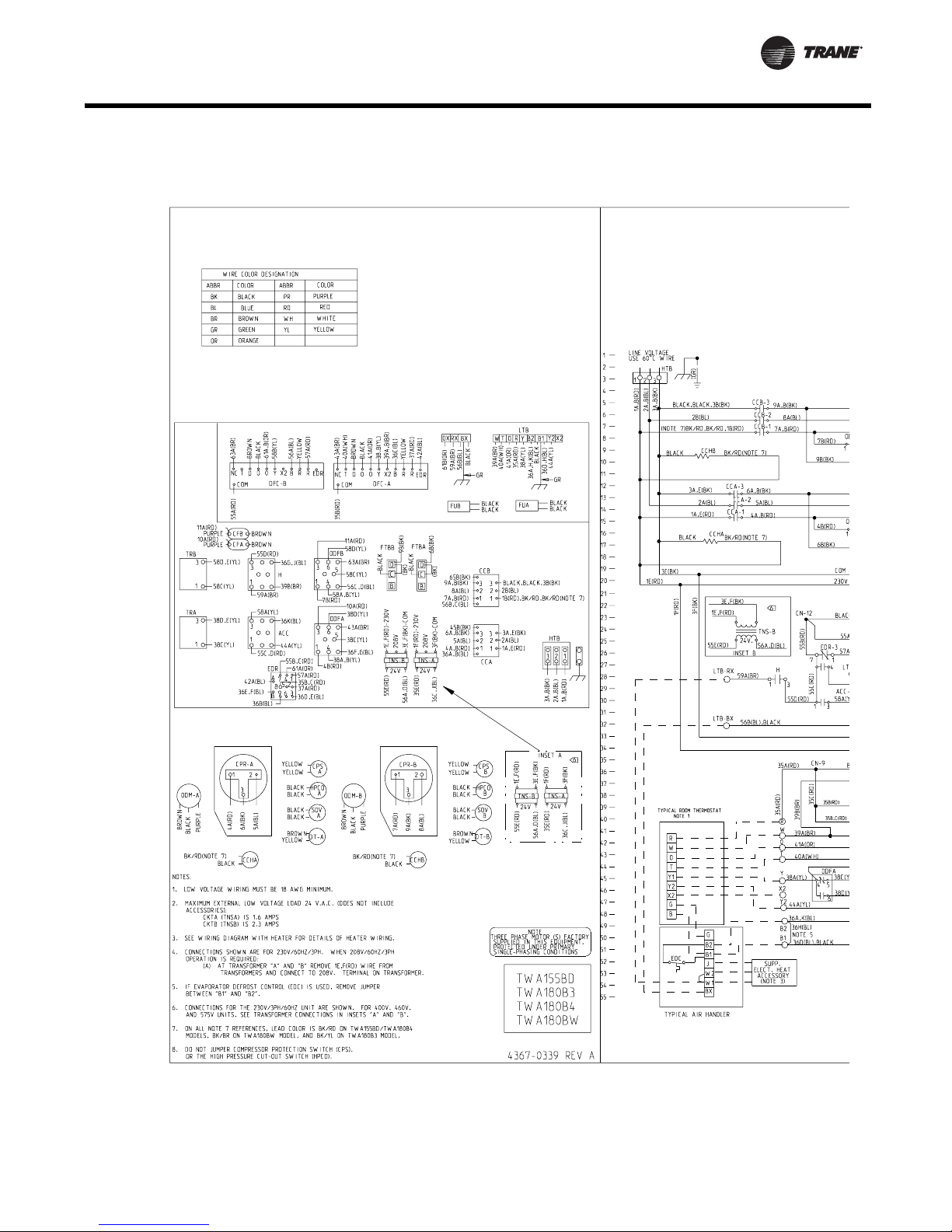
Typical Wiring
Heat Pump Dual Compressor Wiring Diagram
Figure 18. Heat Pump - Dual Compressor. For specific wiring, see individual Service Facts.
SSP-PRC001-EN 39
Page 40

Typical Wiring
Heat Pump Dual Compressor Wiring Diagram
Figure 18. (continued from previous page)Heat Pump - Dual Compressor. For specific wiring, see individual Service
Facts.
40 SSP-PRC001-EN
Page 41

Typical Wiring
Air Handler Wiring Diagram
Figure 19. Air Handler. For specific wiring, see individual Service Facts.
SSP-PRC001-EN 41
Page 42

Dimensional Data
Figure 20. 7½ Tons TWA090 Heat Pump. All dimensions are in inches.
42 SSP-PRC001-EN
Page 43
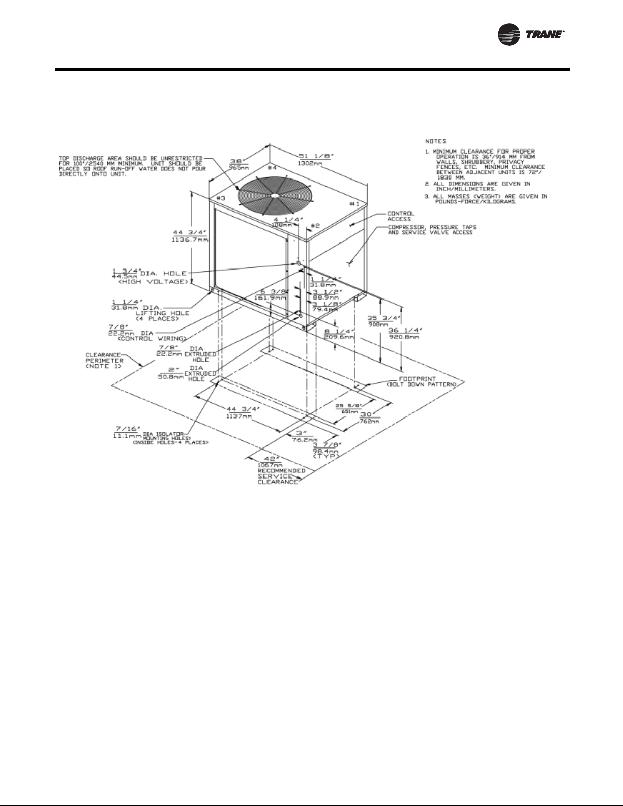
Dimensional Data
10 Tons
Figure 21. 10 Tons TWA120A Heat Pump. All dimensions are in inches.
SSP-PRC001-EN 43
Page 44

Figure 22. 15 Tons TWA180B Heat Pump. All dimensions are in inches.
Dimensional Data
15 Tons
44 SSP-PRC001-EN
Page 45

Dimensional Data
20 Tons
Figure 23. 20 Tons TWA240B Heat Pump. All dimensions are in inches.
SSP-PRC001-EN 45
Page 46

Figure 24. 5 Tons TWE060A, 060B Air Handlers. All dimensions are in inches.
Dimensional Data
5 Tons
Table 39. Air Handler Dimensions (in.)
Tons Model No. A B C D E F G H J K Q
5 TWE060A 48 38 22 8 19-1/2 26 15-7/8 14-1/8 1-7/8 42-1/8 34-5/8
5 TWE060B 48 38 22 8 19-1/2 26 16-1/4 13-1/4 1-1/8 42-1/8 34-5/8
Tons Model No. S V W Y AA
5 TWE060A 3/8 — — 1-1/8 1-7/8
5 TWE060B 5/16 14-3/4 11-1/8 3/4 2
46 SSP-PRC001-EN
Page 47

Dimensional Data
7½ & 10 Ton
Figure 25. 7½ & 10 Tons TWE090A, 120A; TWE090B, 120B Air Handlers. All dimensions are in inches.
Table 40. Air Handler Dimensions (in.)
Tons Model No. A B C D E F G H J K
7½ TWE090A 54 47-1/2 25 11-3/4 22-3/8 22 — 17-3/4 4 45-1/4
7½ TWE090B 54 47-1/2 25 11-3/4 22-3/8 22 20-1/8 16 2-1/8 45-1/4
10 TWE120A 54 63-12 25 19-3/4 22-3/8 22 — 17-3/4 4 45-1/4
10 TWE120B 54 63-1/2 25 19-3/4 22-3/8 22 20-1/8 16 2-1/8 45-1/4
Tons Model No. Q S V W Y AA
7½ TWE090A 38-1/8 1/2 — 15 1-3/8 2
7½ TWE090B 38-1/8 3/8 18-3/4 14 1-1/8 2-1/8
10 TWE120A 38-1/8 1/2 — 15 1-3/8 2
10 TWE120B 38-1/8 3/8 18-3/4 14 1-1/8 2-1/8
SSP-PRC001-EN 47
Page 48

Figure 26. 5-10 Tons TWE060A, 090A, 120A; TWE060B, 090B, 120B Air Handlers
Dimensional Data
5 - 10 Ton
Table 41. Air Handler Dimensions (in.)
Tons Model No. L M N P R T X Z
5 TWE060A,060B 34-5/8 2 7/8 35-5/8 12 1/4 32-1/4 12 1/2 7 5/8 2
7½ TWE090A, 090B 36-7/8 6 5/8 45-1/8 16-1/8 41-3/4 16-1/4 6 7/8 1 3/4
10 TWE120A, 120B 36-7/8 6 5/8 61-1/8 16-1/8 57-3/4 16-1/4 6 7/8 1 3/4
48 SSP-PRC001-EN
Page 49

Dimensional Data
15 Tons
Figure 27. 15 Tons TWE180 Air Handlers. All dimensions are in inches.
SSP-PRC001-EN 49
Page 50

Figure 28. 15 Tons TWE180 Air Handlers
Figure 29. 15 Tons TWE180 Air Handlers
Dimensional Data
15 Tons
Table 42. Air Handler Dimensions (in.)
Tons Model No. A B C D E F G H J K L M N P
15 TWE180B 69 79-1/2 27-5/8 12-3/8 1-5/8 26 25-1/8 49-1/8 56-1/4 15-1/2 19-1/2 77-1/4 1 1/4 48
Tons Model No. R S T U V W Y Z AA AB AC AD AE AF
15 TWE180B 35 35 2-7/8 73-7/8 3-3/4 3-3/8 18 73-7/8 3-3/4 2-7/8 18 3-5/8 35 35
50 SSP-PRC001-EN
Page 51

Dimensional Data
20 Tons
Figure 30. 20 Tons TWE240B Air Handlers
SSP-PRC001-EN 51
Page 52

Figure 31. 20 Ton TWE240B Air Handlers
Dimensional Data
20 Tons
Figure 32. 15 Tons TWE180 Air Handlers
Table 43. Air Handler Dimensions (in.)
Tons Model No. ABCDEFGHJK L M N P
20 TWE240B 71-7/8 92-1/2 30-1/2 18-7/8 4-1/2 31 28 51-7/8 59-1/8 18-1/8 20-7/8 89-1/4 1 3/4 50-7/8
Tons Model No. R S T U V W Y Z AA AB AC AD AE AF
20 TWE240B 39-1/8 39-1/8 4-7/8 82-7/8 4-5/8 3-1/8 20-1/8 82-7/8 4-5/8 4-7/8 20-1/8 3 39-1/8 39-1/8
52 SSP-PRC001-EN
Page 53

Dimensional Data
Accessories, Electric Heater
Figure 33. Electric Heater for 5, 7½ and 10 Ton Air Handlers. All dimensions are in inches.
Figure 34. Electric Heater for 15 and 20 Ton Air Handlers. All dimensions are in inches.
SSP-PRC001-EN 53
Page 54

Accessories, Discharge Plenum and Grille
Table 44. Discharge Plenum and Grille
Tons Model No. A B C
5 BAYPLNM015 37-15/16 21-15/16 28
7½ BAYPLNM016 47-1/2 25 28
10 BAYPLNM017 63-1/2 25 28
Table 45. Discharge Plenum and Grille Dimensions (in.). For use with Electric Heat
Tons Model No. A B C
5 BAYPLNM025 37-15/16 21-15/16 29
7½ BAYPLNM026 47-1/2 25 29
10 BAYPLNM027 63-1/2 25 29
15 BAYPLNM028 79-1/2 27-11/16 35
20 BAYPLNM029 92-1/2 30-7/16 35
Figure 35. Discharge Plenum and Grille (with Electric Heat)
Dimensional Data
Table 46. Discharge Plenum and Grille Dimensions (in.) - No Heat
Tons Model No. A B C
15 BAYPLNM018 79-1/2 27-11/16 22
20 BAYPLNM019 92-1/2 30-7/16 24
Figure 36. Discharge Plenum and Grille (without Electric Heat)
54 SSP-PRC001-EN
Page 55

Dimensional Data
Accessories, Subbase
Table 47. Subbase Dimensions (in.)
Tons Model No. A B
5 BAYBASE001 38 22
7½ BAYBASE002 47-1/2 25
10 BAYBASE003 63-1/2 25
15 BAYBASE004 79-1/2 27-5/8
20 BAYBASE005 92-1/2 30-7/16
Figure 37. Subbase
SSP-PRC001-EN 55
Page 56

Figure 38. 5-20 Tons Rubber Isolators
Dimensional Data
Accessories, Rubber isolators
Table 48. Isolator Dimensions (in.)
Model No. L W H A B C D E
BAYISLT003 3-1/8 1-3/4 1-1/4 1-1/4 3/8 2-3/8 3/8 1/4
BAYISLT004
BAYISLT005
BAYISLT009 3-7/8 2-3/8 1-3/4 1-3/4 3/8 3 3/8 1/4
BAYISLT010
BAYISLT013
BAYISLT014 2-1/4 2 3 1-3/8 3/4 3/8 1/2 —
BAYISLT015
BAYISLT012
BAYISLT015
BAYISLT016
(i)
BAYISLT015 contains quantity 2 of the 2 1/4 x 2 x 3 isolators and quantity 3 of the 3 x 2 1/4 x 4 1/2 isolators.
(i)
(i)
3 2-1/4 4-1/2 1-7/8 1/4 5/8 3/4 —
56 SSP-PRC001-EN
Page 57

Dimensional Data
Accessories, Spring Isolators
Figure 39. 5-20 Ton Spring Isolators
SSP-PRC001-EN 57
Page 58

Weights
Table 49. Unit and Corner Weights (lbs.)
Corner Weights
Tons Unit Model No.
7 TWA090A 390 343 112 89 63 79
10 TWA120A 502 443 149 116 78 100
15 TWA180B 816 740 195 186 175 184
20 TWA240B 970 885 253 250 190 192
Shipping Maximum
(lbs)
Table 50. Accessory Weights (net lbs.)
Tons Unit Model No. RIS Isolators
7½ TWA090A 2 12 1 8 1 23
10 TWA120A 2 12 1 11 1 23
15 TWA180B 2 12 1 22 1 23
20 TWA240B 2 12 1 34 1 23
Net Maximum
(lbs) 1 2 3 4
Steel Spring
Isolators
Anti Short
Cycle Timer
Coil
Guard
ThermostatsLow
Ambient
Figure 40. 7½ and 10 Ton
TWA090A, 120A
Figure 41. 15 and 20 Ton TWA180A, 240B
58 SSP-PRC001-EN
Page 59

Weights
Air Handlers
Table 51. Unit and Corner Weights (lbs.)
Tons
5 TWE060A, B 298 232 59 59 59 59 54 64 64 54
7½ TWE090A, B 388 317 79 79 79 79 73 81 84 77
10 TWE120A, B 439 392 98 98 98 98 95 101 101 95
15 TWE180B 754 692 173 173 173 173 156 174 190 170
20 TWE240B 886 816 204 204 204 204 179 221 228 185
Notes:
1. If application requires stea m or hot water heating coils, field supplied isolators must be utilized.
Unit
Model No.
Shipping
Maximum
(lbs)
Table 52. Accessory Weights (net lbs.)
Discharge
Plenum &
(i)
Grille
No.
Discharge
Plenum &
Grille
Unit Model
Tons
5 TWE060A,B 58 93 3 32/43 14 31 2 9 12 6 —
7½ TWE090A,B 73 123 5 27/45 19 48 2 6 12 6 4
10 TWE120A,B 92 156 7 27/45 23 50 2 7 12 6 4
15 TWE180B 124 230 10 79/100 27 80 2 7 12 6 —
20 TWE240B 145 264 12 79/100 31 88 2 9 12 6 —
(i)
For use when no supplemental heat is supplied.
(ii)
For use with electric heat.
Net
Maximum
(lbs)
Return
(ii)
Grille
1234ABCD
Electric
Air
Heat
Min/Max Subbase
Corner Weights — Vertical Corner Weights — Horizontal
Oversized
Motor
RIS
Isolator
Floor
Mount
RIS
Isolator
Suspended
Mount
Steel
Spring
Isolator
Floor
Mount
Steel
Spring
Isolator
Suspended
Mount
Transformer
Control
Figure 42. Vertical - 5, 7½ & 10 Ton TWE060A, 060B, 090A, 120A, 120B (left), 15 & 20 Ton TWE0180B, 240B (right)
Figure 43. Horizontal - 5, 7½ & 10 Ton TWE060A, 060B, 090A, 120A, 120B (left), 15 & 20 Ton TWE0180B, 240B (right)
SSP-PRC001-EN 59
Page 60

Mechanical Specifications
Heat Pumps
General
Units shall be assembled on heavy
gauge steel mounting/lifting rails
and shall be weather proofed. Unit
shall include a hermetic scroll or
reciprocating compressor(s), plate
fin condenser coil, fans and motors,
controls and holding charge of
nitrogen. Operating Range shall be
between 115°F to 50°F in cooling as
standard from factory. Units shall be
UL 1995 listed and rated in
accordance with ARI Standard 340/
360.
Casing
Unit casing shall be constructed of
18 gauge zinc coated heavy gauge,
galvanized steel. Exterior surfaces
shall be cleaned, phosphatized and
finished with a weather-resistant
baked enamel finish. Units surface
shall be tested 500 hours in salt
spray test. Units shall have
removable end panels which allow
access to all major components and
controls.
Refrigeration System —
Single Compressor
TWA090A, TWA120A units shall
have a single refrigeration circuit.
Each refrigeration circuit has an
integral subcooling circuit. A
refrigeration filter drier, expansion
valve and check valves shall be
provided as standard.
The TWA090A, TWA120A units shall
have both a liquid line and suction
gas line service valve with gauge
port. TWA090A, TWA120A units shall
have one direct drive Trane hermetic
scroll compressor with centrifugal oil
pump providing positive lubrication
to moving parts.
Motor shall be suction gas-cooled
and shall have a voltage utilization
range of plus or minus 10 percent of
nameplate voltage. Crankcase
heater, internal temperature and
current-sensitive motor overloads
shall be included for maximum
protection. Scroll type compressor
shall provide inherently low
vibration and noise by having no
suction and discharge valves.
External high and low pressure
cutout devices shall be provided.
Evaporator defrost control provided
in indoor blower coil unit shall
prevent compressor slugging by
temporarily interrupting compressor
operation when low evaporator coil
temperatures are encountered.
Refrigeration System — Dual
Compressor
TWA180B, TWA240B units shall have
two separate and independent
refrigeration circuits. Each
refrigeration circuit shall have an
integral subcooling circuit. A
refrigeration filter drier shall be
provided as standard.
Units shall have both a liquid line
and suction gas line service valve
with gauge ports. TWA180B,
TWA240B units shall have two Trane
direct drive hermetic scroll
compressors with centrifugal oil
pump and provide positive
lubrication to all moving parts.
Motor shall be suction gas-cooled
and shall have a voltage utilization
range of plus or minus 10 percent of
nameplate voltage. Crankcase
heater, internal temperature and
current-sensitive motor overloads
shall be included for maximum
protection. Scroll type compressor
shall provide inherently low
vibration and noise by having no
suction and discharge valves.
External high and low pressure
cutout devices shall be provided.
Evaporator defrost control provided
in indoor blower coil shall prevent
compressor slugging by temporarily
interrupting compressor operation
when low evaporator coil
temperatures are encountered.
Condenser Coil
Coils shall be internally finned or
smooth bore 3/8" copper tubes
mechanically bonded to configured
aluminum plate fin as standard. Coil
shall be factory pressure and leak
tested to 420 psig air pressure. Metal
grilles with PVC coating for coil
protection is optional.
Condenser Fan and Motor(s)
Direct-drive, statically and
dynamically balanced 26 or 28 inch
propeller fan(s) with aluminum
blades and electro-coated steel hubs
shall be used in draw-through
vertical discharge position. Either
permanently lubricated totally
enclosed or open construction type
motors shall be provided and shall
have built in current and thermal
overload protection. Motor(s) shall
have either ball or sleeve bearing
type.
Controls
Heat pump units shall be completely
factory wired with necessary
controls and contactor pressure lugs
or terminal block for power wiring.
Control wiring shall be 24-volt
control circuit which includes fusing
and control transformer. Units shall
provide external location for
mounting a fused disconnect device.
Time delay timers to prevent
compressors in dual compressor
units from simultaneous start-up and
anti-recycle timers are available as
optional accessories.
Defrost Controls
Electronic timed initiated,
temperature terminated defrost
system with choice of 50, 70, or 90
minute cycle. Timed override limits
defrost cycle to 10 minutes.
Low Ambient Operation
Standard units shall start and
operate to approximately 50°F when
matched with Trane air handlers and
coils. Optional head pressure control
accessory permits operation to 0°F.
Accessories
Low Ambient Head Pressure
Control — Shall modulate the RPM
of unit outdoor fan motor in
response to outdoor ambient
temperatures and liquid line
temperature. Accessory provides
unit cooling operation to outdoor
temperatures of 0°F.
Vibration Isolation Packages —
Shall reduce transmission of noise
60 SSP-PRC001-EN
Page 61

Mechanical Specifications
and vibration to building structures,
equipment and adjacent spaces.
Packages shall be available in either
neoprene-in-shear or spring-flex
types.
Time Delay Relay — Shall prevent
compressors in dual compressor unit
from coming on line simultaneously.
Timer shall be 24-volt, 60 cycle, with
four minute timing period.
Anti-Short-Cycle Timer — Shall
prevent rapid on-off compressor
cycling in light load conditions by not
allowing compressor to operate for
5-7 minutes upon shutdown. Shall
consist of a solid state timing device,
24-volt, 60 cycle with either 5 or 7
minute fixed-off timing period.
Condenser Coil Guard — Metal
grille with PVC coating shall be
provided to alleviate coil damage.
Black Epoxy Coated Condenser
Coil — The black epoxy coils have a
thermoset vinyl coating that is
bonded to the aluminum fin stock
prior to the fin-stamping process.
The pre-coated coils are an
economical option for protection in
mildly corrosive environments.
Air Handlers
General
Air handler units shall be completely
factory assembled including coil,
condensate drain pan, fan motor(s),
filters and controls in an insulated
casing that can be applied in either
vertical or horizontal configuration.
Units shall be rated and tested in
accordance with ARI standard 340/
360. Units shall be UL listed and
labeled in accordance with UL 1995
for indoor blower coil units.
Casing
Unit casing shall be constructed of
zinc coated, heavy gauge, galvanized
steel. Exterior surfaces shall be
cleaned, phosphatized and finished
with a weather-resistant baked
enamel finish. Casing shall be
completely insulated with cleanable,
foil faced, fire-retardant, permanent,
odorless glass fiber material. All
insulation edges shall be either
captured or sealed. Knockouts shall
be provided for unit electrical power
and refrigerant piping connections.
Captive screws shall be standard on
all access panels.
Refrigeration System
The TWE060A, TWE090A, TWE120A
units shall have a single refrigeration
circuit and the TWE060B, TWE090B,
TWE120B, TWE180B, TWE240B units
shall have dual refrigeration circuits.
Each refrigeration circuit is controlled
by a factory installed thermal
expansion valve.
Evaporator Coil
Configured aluminum fin surface
shall be mechanically bonded to 3/8"
internally enhanced copper tubing
and factory pressure and leak tested
at 375 psig. Coil is arranged for drawthrough airflow and shall provide a
double sloped condensate drain pan
constructed of PVC plastic. The drain
pan shall be removable for cleaning.
The condensate drain pan can be
installed in any of four positions
allowing for vertical or horizontal
application and providing external
connections on either side of the
unit.
Evaporator Fan
Double inlet, double width, forward
curved, centrifugal-type fan(s) with
adjustable belt drive shall be
standard. Thermal overload
protection shall be standard on
motor. Fan and motor bearings shall
be permanently lubricated. Oversized
motors shall be available as an
option for high static application. All
indoor fan motors meet the U.S.
Energy Policy Act of 1992 (EPACT)
Controls
Magnetic evaporator fan contactor,
low voltage terminal strip, check
valve(s), and single point power
entry shall be included. All necessary
controls shall be factory-installed and
wired. Evaporator defrost control
shall be included to prevent
compressor slugging by temporarily
interrupting compressor operation
when low evaporator coil
temperatures are encountered.
Filters
One inch, throw-away filters shall be
standard on TWE060A, TWE090A,
TWE060B, TWE090B and TWE120B
model air handlers. Filters shall be
accessible from the side coil access
panel. Filter rack can be field
converted to two inch capability. Two
inch, throw-away filters shall be
standard on TWE180B and TWE240B
models.
Accessories
Electric Heaters — UL and CSA
approved electric heat modules shall
be available for installation directly
on fan discharge. Electric Heaters
shall be available in a wide range of
capacities with one or two stage
control, single-point electric power
connection and terminal strip
connections. Electric heater elements
shall be constructed of heavy-duty
nickel chromium elements internally
wye connected on 480/600 volt, three
phase and delta connected on 208/
240 volt, three phase. Each 208/240
volt heater shall have pilot duty with
secondary backup fuse links for
automatic reset of high limit controls.
Each 480/600 volt heater shall have
automatic line break high limit
controls.
Discharge Plenums and Grilles —
Accessory discharge plenums shall
be available for vertical, free
discharge applications. Plenums shall
be constructed of heavy-gauge, zinc
coated galvanized steel finished with
baked enamel to match the air
handler unit. Grilles shall be satin
finished aluminum and have fourway adjustable louvers.
Return Air Grilles — Accessory
return air grille shall be provided for
vertical front, free return
applications. Grilles shall be installed
in place of the front lower side panel.
Grille shall be satin finished
aluminum with non-adjustable
louvers.
Mounting Subbase — Available for
vertical floor mount configurations.
Subbase shall be constructed of
heavy gauge, zinc coated galvanized
steel with baked enamel finish to
match air handler unit. Subbase is
required in the vertical air flow
application for condensate drain
trapping and when isolators are
required.
Vibration Isolators — Shall reduce
transmission of noise and vibration
to building structures, equipment
and adjacent spaces. Packages shall
SSP-PRC001-EN 61
Page 62

be available in either neoprene-in
shear or spring-flex types in floor or
suspended mountings.
Oversized Motors — Field installed
oversized motors shall be available
for high static pressure applications.
Control Options
Standard Indoor Thermostats —
Two stage heating and cooling
operation or one stage heating and
cooling thermostats shall be
available in either manual or
automatic changeover.
Programmable Electronic Night
Setback Thermostat — Shall
provide heating setback and cooling
setup with 7-day programming
capability.
Outdoor Thermostat — Shall
provide staging control of electric
heaters based on a set outdoor
temperature.
Mechanical Specifications
62 SSP-PRC001-EN
Page 63

Page 64

Tr a n e
A business of American Standard Companies
www.trane.com
For more information, contact your local Trane
office or e-mail us at comfort@trane.com
Literature Order Number SSP-PRC001-EN
Date February 2008
Supersedes SSP-PRC001-EN (July 2007)
Trane has a policy of continuous product and product data improvement and reserves the right to
change design and specifications without notice.
 Loading...