

Page 1

Installation Guide
© 2007 - 2012 Tramigo™ Ltd. All rights reserved. Under the copyright laws, this manual cannot be reproduced in any
form without the prior written permission of Tramigo™.
Tramigo™ T23 Fleet
Installation Guide
V1.07.5
Page 2

Installation Guide
© 2007 - 2013 Tramigo™ Ltd. All rights reserved. Under the copyright laws, this manual cannot be reproduced in any
form without the prior written permission of Tramigo™. Page
2
Contents
1 Preface ................................................................................................ 3
2 Installation ......................................................................................... 4
2.1 Installation Tools ................................................................................. 4
2.2 Installation Site .................................................................................... 5
2.3 Unit Location ........................................................................................ 5
2.4 Antenna Location ................................................................................. 5
2.5 Personal Assistance Button Location.................................................... 5
2.6 Installation without Internal Backup Battery ...................................... 5
2.7 Internal/External Backup Battery ........................................................ 6
2.8 Recommended Installation Sequence .................................................. 6
3 Plan ..................................................................................................... 7
3.1 Identifying I/O ports on your T23 FLEET ............................................. 7
3.2 Configuring I/O ports ........................................................................... 8
3.3 Mounting the T23 FLEET ....................................................................... 8
4 Connect ............................................................................................... 9
4.1 Fitting the SIM card.............................................................................. 9
4.2 Steps in Fitting SIM card to T23 FLEET ................................................. 9
4.3 T23 FLEET Wiring and Connections .................................................... 11
4.4 Power Connection .............................................................................. 11
4.5 Ignition Sensing Connection .............................................................. 11
4.6 Personal Assistance Button or T23 FLEET-ATB ................................... 12
4.7 Sensor wiring ..................................................................................... 12
4.8 GPS External Antenna Option ............................................................. 12
4.9 T23 FLEET 24V Installation ................................................................ 13
5 Configure .......................................................................................... 14
5.1 Configuration Steps ............................................................................ 15
6 Test ................................................................................................... 16
7 Mount ................................................................................................ 17
7.1 How to remove FAKRA from GPS antenna: ........................................ 18
8 Wiring Diagram ................................................................................ 19
9 T23 FLEET Spare Parts & Order Numbers ........................................ 20
10 Troubleshooting ............................................................................... 21
Page 3

Installation Guide
© 2007 - 2013 Tramigo™ Ltd. All rights reserved. Under the copyright laws, this manual cannot be reproduced in any
form without the prior written permission of Tramigo™. Page
3
1 Preface
Failure to comply with the following warnings and safety information may
invalidate warranty, certification or type approval of this product.
Internal components containing beryllium oxide may be used in this equipment. Dust from this
material is a health hazard if inhaled or allowed to come into contact with the skin. Outmost care
must be taken when ha ndling these components.
Unauthorized modification to this equipment or associated accessories is forbidden without the
express permission and agreement from the product manufacturer.
Safety Information
Please adhere to the following Safety and Installation information at all times.
Supply Voltage : +6V minimum to +27V maximum with or without batt ery
Fuses : Built-in fuse
WARNING!
This equipment may only be located i n a position where it cannot interfere with
the normal operation of the vehicle or pr esent a hazard to the driver or
passengers. Care must also be taken in ro uting all cables so that the insulation
does not become worn or damaged.
Installation Information
All installation and service work must be carried out in accordance with MPT 1362, MPT 1372,
RQAS, VSIB, 95/54/EC, ISO 21609 and / or any other statutory guidelines or directives currently
in force.
Therefore it is strongly recommended that the T23 FLEET unit is installed and commissioned by
suitably trained and qualified Installation Personnel i.e. in the UK those who are accredited and
registered by the Vehicle Systems Installation Board (www.vsib.co.uk).
Important Notes!
Unauthorized changes or alterations t o the equipment or on the installation will invalidate
certification issued by the Approved Accreditation Body and may also affect the vehicle
manufacturers warranty.
Under no circum stances may any part of the T23 FLEET system be installed inside the engine
compartment area.
This unit should not be placed to direct sunlight or expose to high temperature.
This equipment should not be operated in hazardous environments i.e. areas that contain
explosive materials or flammable vapours.
This equipment should not be operated in aircraft or in close proximity to medical equipment.
Page 4
Installation Guide
© 2007 - 2013 Tramigo™ Ltd. All rights reserved. Under the copyright laws, this manual cannot be reproduced in any
form without the prior written permission of Tramigo™. Page
4
2 Installation
Before you begin installing and configuring the system please ensure that you have read this
manual thoroughly, referring to any supplementary information provided for the T23 FLEET unit
and user options as required.
(**OPTIONAL)
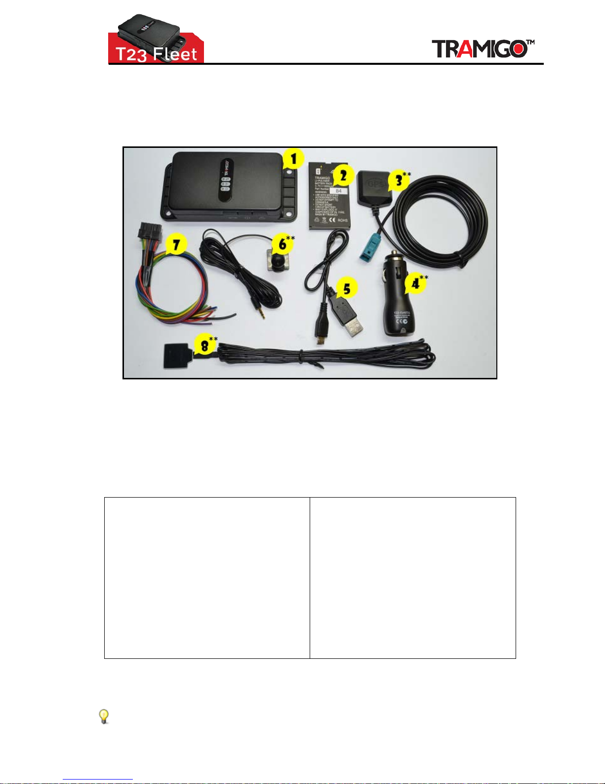
Figure 1 - T23 FLEET and Automotive Installation Kit
1 - T23 FLEET Unit
2 - T23 FLEET-BAT
3 - T23 FLEET-GPS Antenna
4 - T23 FLEET-CLA (Cigarette Lighter Adaptor)
5 - T23 FLEET-USB
(micro USB for portable charger)
6 - T23 FLEET-AMIC (microphone)
7 - T23 FLEET I/O
8 - T23 FLEET-SOS/ATB external
2.1 Installation Tools
Automotive screwdrivers, spanners,
socket sets
Wire cutter, pliers
Voltage Meter
Automotive Electrical Tape (regular
electrical tape will unwrap in 6 months)
Waterproof and heat resistant
Automotive 2 way tape (3M has a good
tape that is used to secure trim on the
vehicle exterior)
Foam tape – for preventing rattles
Small Ty-Wraps (for securing wires and
case)
Portable soldering Iron
Flashlight
Alcohol and cloth
Spare T23 FLEET unit and accessories
(in case of component failure)
Tramigo™ T23 FLEET wiring diagrams
(included in this document)
Wire connectors and crimping tool or
Posi-Lock wire con nectors
GSM Phone or PC (for configuration)
Portable GPS receiver (for testing GPS
signal strength). Any unit will work as
long as it s
hows the GPS signal
strength.
Charge the battery overnight before using your T23 FLEET for the first time.
Page 5

Installation Guide
© 2007 - 2013 Tramigo™ Ltd. All rights reserved. Under the copyright laws, this manual cannot be reproduced in any
form without the prior written permission of Tramigo™. Page
5
2.2 Installation Site
The installation can be performed in any well ventilated and well lit area as found in a car
dealership or accessory installation bay. There is no requirement to raise the vehicle. To
obtain the first GPS lock, a clear view of the sky is required, which should be considered if
designing a custom install centre. A GPS repeater can be used to obtain a signal inside a
building.
Care should be taken to avoid scratching the vehicle during the installation process.
Protective clothing and vehicle covers should be used.
Installations are also performed on the customers home or office site, so a portable
installation toolkit is required.
2.3 Unit Location
Your T23 FLEET unit can be mounted anywhere inside your vehicle or boat where the unit
will not get wet and not exposed to excessive heat. The most common locations are behind
the dashboard, under the centre consol e, and under a side panel in the back of the vehicle.
Pick a location where you can secure the unit firmly to prevent any rattling sounds after
installation.
2.4 Antenna Location
In order for GPS to function correctly, the GPS antenna should have a signal quality of 60%
or higher in order to receive data from the satellites. Example, if the vehicle is parked in a
metal-clad building then the performance of the T23 FLEET platform may be impeded.
Whenever possible, it is preferred to park the vehicle in a location where the antenna will
have a clear all round view of the sky during installation time t o t est the signal strength.
The antenna and wires should be hidden from view by the installer.
Common locations are:
• Under the dashboard as far to the front of the vehicle as possible
• Under the plastic cover near the windshield wipers
• Under the plastic cover of the front or rear bumpers
• In the license plate lamp (on SUV types)
• In the side mirrors (when space permits)
Places to avoid are:
• Under the roof or roof posts
• Under rear window defogger wires
2.5 Personal Assistance Button Location
It is recommended that the Personal Assistance Butto n, when fitted, is located within easy
reach and visibility of the vehicle driver, or where required in a covert location. Typically it
will be fitted into a blank switch position.
2.6 Installation without Internal Backup Battery
T23 Fleet works without internal backup battery. Power is supplied through IO cable pins 1
and 3 for example from the vehicles main lead battery. Note that unit shut down
immediately if no power supply present.
Page 6

Installation Guide
© 2007 - 2013 Tramigo™ Ltd. All rights reserved. Under the copyright laws, this manual cannot be reproduced in any
form without the prior written permission of Tramigo™. Page
6
2.7 Internal/External Backup Battery
Internal Li-Polymer backup battery can handle temperatures up to 65 °C (149 ºF). In
countries with hot climate this can be an issue. To ensure device proper functionality, it is
highly recommended to use external lead battery backup, please see Tramigo accessories.
The internal backup battery can be removed and backup power is supplied from external
lead battery.
The external backup battery power is supplied trough pins 2 and 4.
Note: If external backup battery is used, do not use internal backup battery at the same
time.
2.8 Recommended Installation Sequence
The following installation sequence is recommen d ed. Please refer to the instructions
elsewhere in this document for further details.
1. Plan the whole installation and de termine suitable locations, mounting ar rangements
and cable routes for all hardware items.
2. Connect Fit SIM card. Temporarily mount the main T23 FLEET unit and temporarily
connect all wiring, while still able to see the status lights on the unit
3. Configure the unit
4. Test that all hardware features are working
5. Mount Complete the permanent installation and wiring
o Perform final test of T23 FLEET functions.
o Test that all vehicle butt ons and switches still work.
Page 7
Installation Guide
© 2007 - 2013 Tramigo™ Ltd. All rights reserved. Under the copyright laws, this manual cannot be reproduced in any
form without the prior written permission of Tramigo™. Page
7
3 Plan
Plan your complete installation first to avoid re-wiring later. T23 FLEET has four inputs and
three outputs.
INPUT consists of the following:
1. Ignition Sensing
2. Personal Assistance Button/ATB (or/and)
3. Customized Input (preferably for sensors)
4. Customized Input (preferably for sensors)
OUTPUT consists of the f ollow ing:
1. Immobilizer (12/24V)
2. Customized Output (for relays/switches)
3. Customized Output (for relays/switches)
3.1 Identifying I/O ports on your T23 FLEET
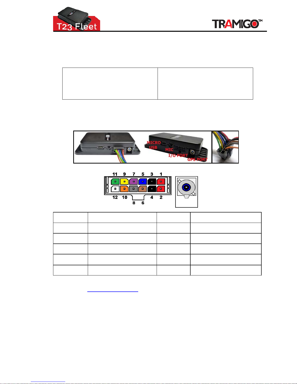
Connect your I/O cable to your T23 Fleet. Then lay the m on a flat surface. Make sure the
I/O cable does not twist and is parallel to the surface.
Figure 2 - T23 FLEET I/O PORT & I/O CABLE
1- RED
"+ power source" (from 6-24V supply
of engine)
7- VIOLET
INPUT 3 / Customized Input
(preferably for sensors)
2- RED
"+ power source" (from 6-24V supply
of engine)
8- GREY
INPUT 4 / Customized Input
(preferably for sensors)
3- BLACK
GND (any metallic chassis of engine)
-ground
9- YELLOW
OUTPUT 1 / Immobilizer (12V/24V)
4- BLACK
GND (any metallic chassis of engine)
-ground
10- ORANGE
OUTPUT 2 / Customized Output
(preferably for relays/switches)
5- BLUE
INPUT 1 / Ignition Sensing
11- GREEN
OUTPUT 3 / Customized Output
(preferably for relays/switches)
6- BROWN
INPUT 2 / SOS or ATB
12- N/A
not used
Figure 3 - I/O CABLE Co nf iguration Table
Contact [email protected] for T23 FLEET customized I/O instructions.
Page 8
Installation Guide
© 2007 - 2013 Tramigo™ Ltd. All rights reserved. Under the copyright laws, this manual cannot be reproduced in any
form without the prior written permission of Tramigo™. Page
8
3.2 Configuring I/O ports
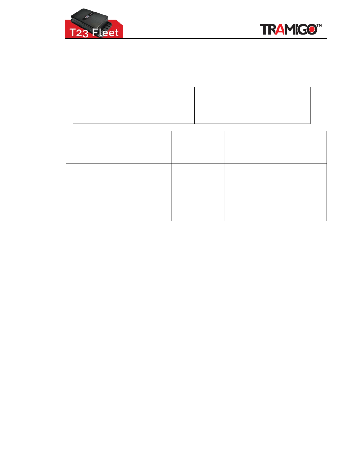
Inputs and outputs can be configured by INPUT and OUTPUT commands.
For Advanced use only!
INPUT default settings:
• INPUT,1,IGNITION,IGNITION,1,0,BOTH
• INPUT,2,SOS,SOS,0,0,ON
• INPUT,3,SENSOR,SENSOR,1,0,ON
• INPUT,4,GENERAL,INPUT,1,0,ON
OUTPUT default settings:
• OUTPUT, 1,IMMOBILIZER,DISABLE,1,
• OUTPUT, 2,GENERAL,OUTPUT,1,0
• OUTPUT, 3,GENERAL,OUTPUT,1, 0
INPUT DEFINITION OUTPUT
(1 -4) corresponds to PINS 5 -8 ID (1-3): Output number PINS 9-11)
(1-4): 1 = Ignition, 2 = SOS,
3 = General/Sensor , 4 = Ha nd sfre e
TYPE (1-2): 1 = Immobilizer, 2 = General
Defines the name of the command for
turning on/off the reporting
LITERAL (TEXT)
Defines the name of the command for
turning on/off the reporting
(1/0): Defines if 0 or 1 used for O N HIGH (1/0): Defines if 0 or 1 used for O N
(0-9999): Wait (ms) before registering
input event (to filter noise)
DELAY N/A
(ON/OFF/BOTH): When reports are sent REPORT WHEN N/A
N/A TIME
(0-9999): Time (ms) how long output
signal is sent, 0 = continuous
Important Note!
All inputs (SOS, Ignition, and Sensor) use 3V minimum and 12V maximum for unit to detect
"ON" state.
3.3 Mounting the T23 FLEET
After checking that all the functions are working properly, you are ready to permanently mount
your unit. Your T23 FLEET unit can be mounted anywhere inside your vehicle or boa t where the
unit will not get wet. The most common locations are behind the dashboard, under the centre
console, and under a s ide panel in the back of the vehicle. Pick a location where you can secure
the unit firmly to prevent any rattling sounds after installation.
In general, you can expect that a mounting situation under the dashboard of a vehicle will be
satisfactory.
Page 9
Installation Guide
© 2007 - 2013 Tramigo™ Ltd. All rights reserved. Under the copyright laws, this manual cannot be reproduced in any form
without the prior written permission of Tramigo™. Page
9
4 Connect
4.1 Fitting the SIM card
Before fitting the SIM card
• If you have not already registered your SIM card with the mobile network, you should do this
before proceeding. Please refer to the appropriate mobile network operator instructions on
how you do this.
• Check that the SIM card can send and re cei ve SMS usi ng a mobile phone
• Ensure that the SIM card is not protected by a PIN number
• For prepaid accounts, ensure that there is sufficient load or credits to send SMS
• It is recommended to use a new SIM card to ensure good contact with the SIM reader
• Record the phone number of the SIM card
Important Note!
When inserting or removing the SIM card from the T23 FLEET, it is necessary to:
• Remember to turn off the power first before removing the battery
• Do not bend or scratch the card
• The golden chip should be kept clean at all times
• To prolong the life cycle of the card, avoid any un necessary insertion or removal of the card.
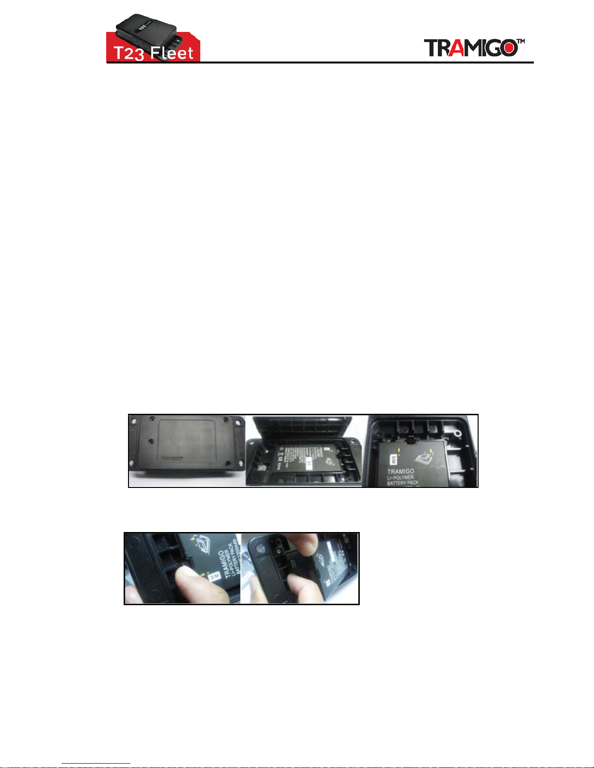
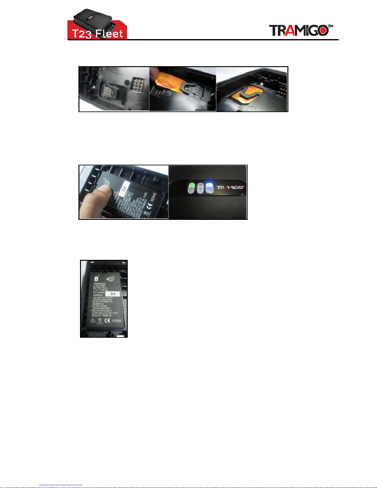
4.2 Steps in Fitting SIM card to T23 FLEET
1. Unscrew the T23 FLEET back panel/cover
2. Push the battery lock to lift the battery and remove it.
Page 10
Installation Guide
© 2007 - 2013 Tramigo™ Ltd. All rights reserved. Under the copyright laws, this manual cannot be reproduced in any form
without the prior written permission of Tramigo™. Page
10
3. Pull the SIM card holder lock up a bit just to loosen the SIM holder, then push forward to fit the
SIM card.
Note: Put SIM Card wherein the gold plate touches the SIM reader pins. Follow the
shape of the SIM holder.
4. Put back the battery and gently push it downward to lock it.
Note: Remember to check first the GSM signal stability before assembling the unit
back, the RED light should b e O FF.
5. Put the back panel/cover. You may return the back cover loosely screwed or unscrewed
since it may fit well on the unit.
Page 11
Installation Guide
© 2007 - 2013 Tramigo™ Ltd. All rights reserved. Under the copyright laws, this manual cannot be reproduced in any form
without the prior written permission of Tramigo™. Page
11
4.3 T23 FLEET Wiring and Connections
Important Notes!
Unauthorized changes or alterations to the equipment or the installation will invalida te certification
issued by the Approved Accreditation Body and could also affect the vehicle manufacturer’s
warranty. If in doubt only connect T23 FLEET to the vehicle power.
All wiring should be safely secured to avoid damage from, or chaffing by, any hot or moving parts.
Position the wiring carefully to avoid the possibility of snagging or impact damage during the
normal use of the vehicle.
Before any holes are drilled, check that no parts, wires, pipes or tanks could be damaged at the
other side of the hole. Suitable grommets must be used where wires are routed through body
panels to prevent short circuits to the chassis.
Leave in-line fuses out of holders until the installatio n is complete.
Cable Assemblies
The T23 FLEET has one IO cable/Immobilizer (12/24V) for power, ignition sensing or external
personal assistance button.
When you configure the T23 FLEET you will be able to carry out tests to determine whether
suitable GSM and GPS signals are being received. I f in doubt about the suitability of your planned
location, it is recommended that you only install it temporarily until you are able to carry out the
appropriate configuration tests, check chapter 3.3.1 for detailed s teps.
4.4 Power Connection
T23 FLEET I/O cable is used to connect to permanent vehicle power in the fuse box or directly to
the car battery. Take a new line which is NOT used to any other car application. Permanent power
source has to be selected carefully
Make sure that there is NO sound from the device when selecting specific power line. NOT all
power lines are suitable.
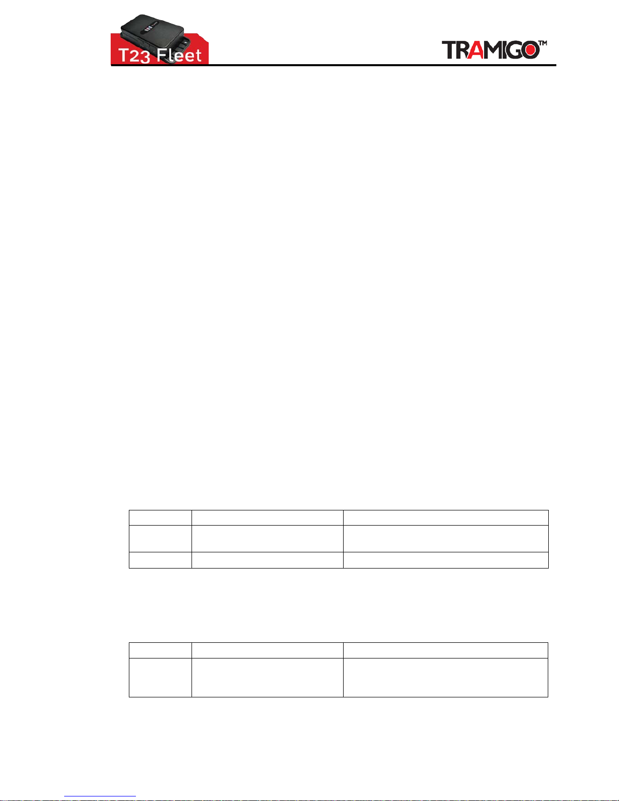
Wire Colour Description Notes
Red Vehicle Supply Positive (+ve) Connect to a permanent Positive supply (6 to
24V)
Black
Vehicle Supply Negative (-ve)
Connect to permanent Negative.
Mandatory: Always check that unit's I/O cable Power and Ground wires are protected with a
1 ADC fuse.
4.5 Ignition Sensing Connection
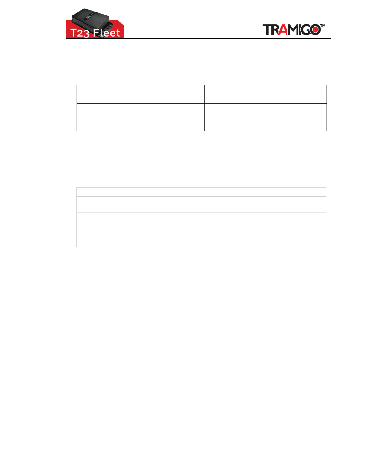
Wire Colour
Description
Notes
Blue Ignition Sensing Connect pin 5 wire to ignition switch which
has POWER ON for the whole driving trip not
only for cranking
(Note: if installing on a motorbike, it is recommended to tap BLUE and RED wires to
ignition line to optimize power consumption and management)
Page 12
Installation Guide
© 2007 - 2013 Tramigo™ Ltd. All rights reserved. Under the copyright laws, this manual cannot be reproduced in any form
without the prior written permission of Tramigo™. Page
12
4.6 Personal Assistance Button or T23 FLEET-ATB
Connect the 2 wires from the Personal Assistance Button to:
Wire Colour Description Notes
Brown SOS/ATB pin connection Connect one end of SOS to pin 6 wire
Red Vehicle Supply Positive (+ve) Connect other end of SOS/ATB to a positive
supply from car (low voltage recommended)
Note: Be sure that serial 39kOhm/0.125W
basic resistor is installed
Note the personal assistance button can also be used to trigger the phone button in situations
where a 3
rd
party hands free kit (in-car speaker and microphone) is attached to the T23 FLEET.
´
4.7 Sensor wiring
Wire Colour Description Notes
Violet or
Grey
Customizable Inputs (for sensor) Connect one end of sensor motor to any of
pin 7 or pin 8 wire
Red Vehicle Supply Positive (+ve) Connect other end of s ensor motor to a
positive supply from car (low voltage
recommended)
Note: Be sure that serial 39kOhm/0.125W
basic resistor is installed
Or this maybe the same a s when connecting the SOS/ATB or Ignition input.
Any sensor that has a digital circuit can be used.
4.8 GPS External Antenna Option
This option is needed when it is not possible to install the T23 FLEET in a location where the
internal GPS antenna will work. This option allows the antennas to be located in a different
location within the vehicle.
The GPS antenna should be positioned horizontally and located in a position where it will have
over 60% signal quality. The ideal location in most cars is in the underside of the dashboard;
however, it is important to ascertain that there are no conductive materials present in the
construction of the d ashboard prior t o fitting the antenna.
The GPS antenna must have the black side facing toward the sky. The flat side with the magnet
faces the ground.
Important Note!
The performance of th e equi pment may be impeded if the an te nn a i s mounted
beneath or in very close proximity to electrically conductive materials, such as metal,
certain types of plastic, metalled film or laminate (tinted) windscreens. If this applies
to your vehicle please install the antenna elsewhere.
Page 13

Installation Guide
© 2007 - 2013 Tramigo™ Ltd. All rights reserved. Under the copyright laws, this manual cannot be reproduced in any form
without the prior written permission of Tramigo™. Page
13
4.9 T23 FLEET 24V Installation
Older truck installations which have bee n measured to provide constantly more than 24V can
cause unwanted behaviour, such as, T23 FLEET unit stops charging due to damaged I/O p ort; or
unit stops responding; or unit hangs.
Recommended Solution:
1. If possible , locat e the vehicle’s regulated power supply (which covers the radio and other
electronic devices) and tap from that source. Usually, the power from that node is only 14V or
less and is more stable because it is regulated compar ed to those connected directly from the
batteries.
2. Use resistors if step 1 is not available, a 30 watts*, 35 Ohms resistor will lower the current of
the battery to your adaptor, protecting it from high current spikes.
Tip: Choose the resistor with heat sink; this will help lower the heat
3. Use terminals or Positaps to tap wires safely. This will r educe risk of fires and car warranty
issues.
4. “Good grounding” is very important. Poor grounding may result to undercharging and T23
FLEET accessories will not work normally. To achieve good grounding, me asure the resistance
of the chassis and compare it directly to the battery’s negative terminal. The closer the
reading to the battery’s reference impedance, the more ideal is the grounding.
5. Check the installation wiring. Always measure the total voltage to check for its voltage drop.
Important Note: Lo os e w ire ta p ping should be re-soldered to avoid heat and power
loss.
6. Insulate all wires to avoid short circuit with automotive electr ical tape or heat shrinks.
7. Remove the car battery before any welding or work to do on the engine. This will avoid voltage
spikes that will damage the T23 FLEET and its accessories.
8. Jump start using another vehicle (espe cially dual batteries) can cause a power spike. The T23
FLEET must be disconnected first from power supply to avoid short circuit.
*Contact
[email protected] for further assistance on adding resistor to the connection.
Page 14
Installation Guide
© 2007 - 2013 Tramigo™ Ltd. All rights reserved. Under the copyright laws, this manual cannot be reproduced in any form
without the prior written permission of Tramigo™. Page
14
5 Configure
After completion of the Installation as described in Section 2, you are ready to configure your T23
FLEET.
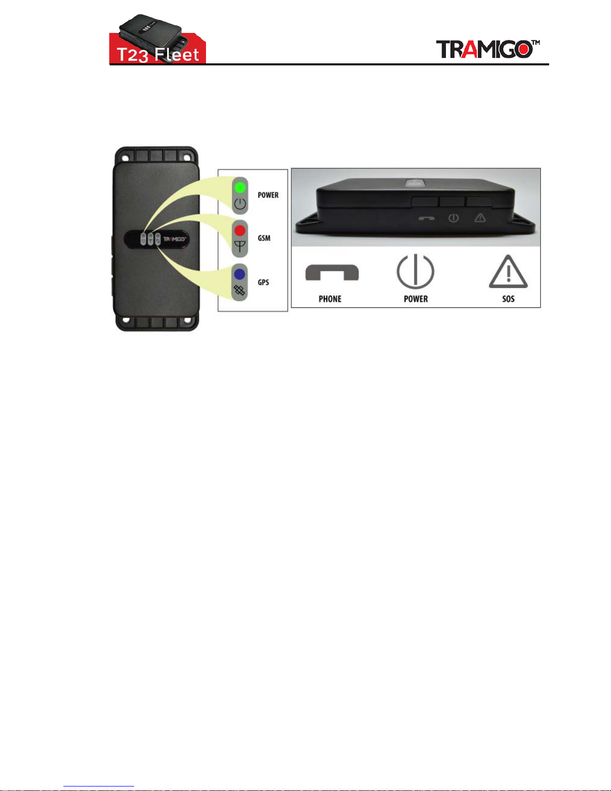
Figure 3 - T23 FLEET Control Panel
Your T23 FLEET has 3 lights to indicate the status of the unit. Green means OK and red and blue
means that you have a problem. T23 FLEET buttons require you to press for 2 seconds to prevent
accidental triggering.
Power LED - Green:
Flashing (5 seconds) Power is on
On Charging
Off Power is off or T23 FLEET is sleeping
Power LED - Orange:
Flashing (5 seconds) Power is ON but is too low
Power LED - Yellow:
On Charging and the power is still low
GSM LED – Red:
On T23 FLEET is not connected to the GSM network
Off T23 FLEET is connected to the GSM network
Flashing T23 FLEET is having problems sending a SMS.
GPS LED - Blue:
On T23 FLEET does not have a GPS fix
Off T23 FLEET has a GPS fix
Power Button Press for 2 seconds to activate
Personal Assistance Button
(SOS/ATB) Press for 2 seconds to activate.
When using an exter nal SOS/ATB button, the T23 FLEET is configured to arm the Alarm by
pressing the button for le ss than 5 seconds. The external SOS/ATB can also be used to activate the
phone functions.
Phone Button Press once to answer incoming call
Press for 2 seconds or more to initiate an outgoing call to User 1,
press a second time for User 2, etc. Second and third press does
not have to be 2 second s.
Incoming call is indicated by the GSM and GPS lights flashing
together.
Page 15

Installation Guide
© 2007 - 2013 Tramigo™ Ltd. All rights reserved. Under the copyright laws, this manual cannot be reproduced in any form
without the prior written permission of Tramigo™. Page
15
Remote Assistance Button Press for 5 seconds or more to activate Assistance message. Press
for 0.2 to 1.9 seconds to use as phone button. Second press must
be within 1 second to dial 2
nd
speed dial number.
5.1 Configuration Steps
• Check that the green Power light is solid ON (charging) or emitting a short flash every 5
seconds (fully char ge d) .
• Check that the red GSM light is OFF.
• Read the instructions in the T23 FLEET User Manual.
• Send the following SMS to your T23 FLEET in upper or lower case from the Owner’s phone
if possible:
OWNER
Note: It is the same with Owner,0000 from previous re gistra tion.
• T23 FLEET will respond with a text message stating:
Tramigo: Owner, +635551234 registered
• This means that you a re now the Owner of T23 FLEET and it will accept any commands
that you issue to it, provided they came from the same mobile phone number as you used
for this setup.
o If the Owner’s phone is not available you can ad d their number with the
Adduser command:
AU,phoneNum,OWNER
If you have Ignition Sensing connected, then you need to issue the following commands:
o Set,IgnitionInputGPIO,1
o Set,IgnitionInputShock,0
Note: T23 Fleet’s default configuration is using shock sensor for ignition sensing.
If you want the SOS button as ALARM, then you need to issue the following commands:
o Set,SOSGPIO,1
o Set,SOSMinpressTime,2000
Page 16

Installation Guide
© 2007 - 2013 Tramigo™ Ltd. All rights reserved. Under the copyright laws, this manual cannot be reproduced in any form
without the prior written permission of Tramigo™. Page
16
6 Test
Test all the wiring connections and GPS Antenna.
• Check the GPS antenna by moving the vehicle to a location with a clear view of the sky.
When the blue GPS light goes off (1-3 minutes) se nd a FIND command to check the
location. Send STATUS command to check GSM and GPS levels.
• If Ignition sensing (blue wire from Pin 5 of T23 FLEET-IO) is connected, test by
o Setting the Parameter
Set,IgnitionInputGPIO,1
Set,IgnitionInputShock,0
o And turning ON the Ignition reporting by sending Ignition,On
o Turn On and Off Ignition switch and you should receive SMS each time during
the Ignition switching
• Test the external SOS button by pressing for 2-3 seconds. You should rece ive an SMS
from the unit.
• Test Alarm by sending command to the device.
o Send Alarm,On
o Shake unit – you should receive Motion Alarm
• If the Sensor/s are connected, test by
o Turning on Sensor reporting
o Send Sensor,On
o Activate and deactivate the sensor and by default you should receive one (1)
SMS during activation.
Page 17
Installation Guide
© 2007 - 2013 Tramigo™ Ltd. All rights reserved. Under the copyright laws, this manual cannot be reproduced in any form
without the prior written permission of Tramigo™. Page
17
7 Mount
Tips: You now have an opt ion to install the T23 FLEET units without the battery. This installation can
be done in areas where temperature exceeds the battery operation range of 60°C.
There are 2 primary methods of mounting the T23 FLEET unit:
1. Use the 4 screw holes to attach to a flat surface inside the vehicle. Use self drilling sheet-
metal screws, diameter max ST 4,2 mm, length about 20mm, cross recessed, pan head.
2. Use double-sided automotive grade tape to attach the case to the vehicle.
You may choose to mount the T23 FLEET somewhere covertly e.g. under the dashboard, but in all
cases the T23 FLEET GPS antenna must be placed such that sufficient signal quality is available to the
antenna to allow for GPS signal reception from the orbiting GPS satellites and cellular radio
communications with the mobile radio netw ork. GPS signals do not pass through metal or electrically
conductive material.
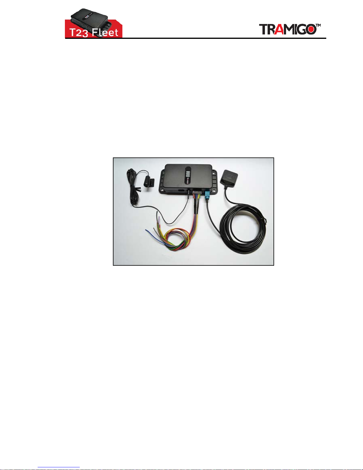
Figure 4 - T23 FLEET Automotive Installation/Wires Connected
Check your windscreen: Should the windscreen be provided with heating that us es a metal film or
fine wires built into the windscreen, or features a special heat reflecting athermic layer, then the GPS
signal will be screened off from the T23 FLEET.
The T23 FLEET should then be mounted at the side of the windscreen where there is sometimes a
special zone free of the metallization.
If this does not work, then you can place the external GPS antenna under the windshield wipers, front
or rear bumpers, or any location where o nly plastic covers the antenna. If you need to run the GPS
antenna cable through the engine compartment, use a standard plastic automotive grade shrouding to
protect the cable.
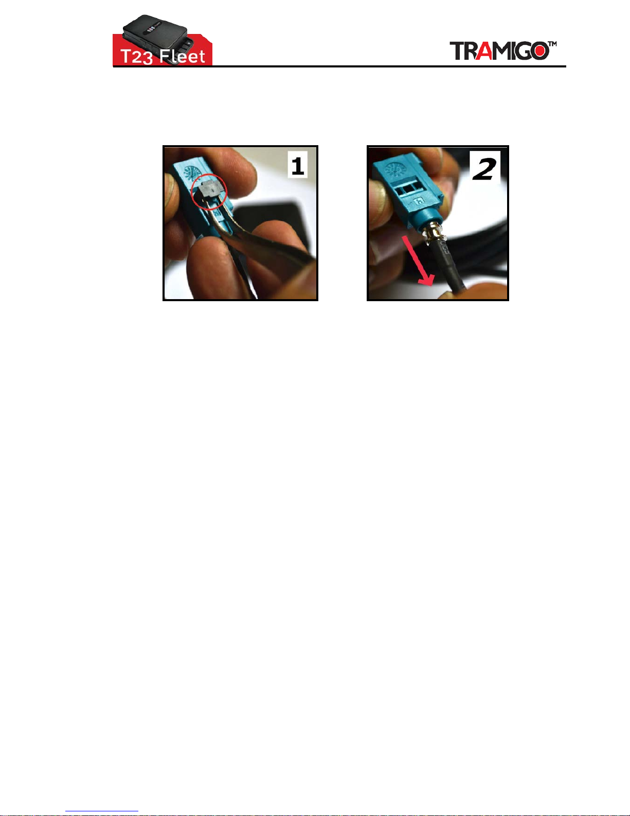
TIPS: T23 FLEET GPS antenna comes with new FAKRA connector and may not fit on smaller holes
during the installation. You have the option to remove it so the GPS antenna would still fit according
the desired location then after the installation, return back the FAKRA connector in reverse steps of
how you removed it.
Page 18
Installation Guide
© 2007 - 2013 Tramigo™ Ltd. All rights reserved. Under the copyright laws, this manual cannot be reproduced in any form
without the prior written permission of Tramigo™. Page
18
7.1 How to remove FAKRA from GPS antenna:
1. Pull out the Fa kra lock (black) using a pair of tweezers.
2. Gently pull the GPS cable o ut from the Fakra connector.
Window Tinting
GPS signals are blocked by metal surfaces which can include some brands of window film that contain
metal particles. To ensure that GPS, cell phone, smart tag, and radio reception is not affected either:
1. Use a non-metallic tint
2. Avoid tinting the front windshie ld where the T23 FLEET unit is located (World wide le g islative
trend is to ban windshield tinting due to increased risk of accidents)
3. Leave a 15 cm gap at the bottom of the windshield and place the T23 FLEET by this opening.
This still provides security for vehicle occupants.
4. Use the External GPS Antenna a nd place the GPS antenna under the front bumper or under
the windshield wipers – as long as the antenna is not covered by metal.
The list of good quality non-metallic film includes the 3M film, Madico CharcOOl (not Madico CharcOAl),
Huper Optik Ceramic (Stark), and FormulaOne Pinnacle (ceramic film). Costs for good quality metallic
film is similar to non-metallic film.
WARNINGS:
• T23 FLEET should be installed in a cool place where air can pass through to
avoid unit overheating.
• If you are to install T23 FLEET under the dashboard, make sure that upper or
lower base of the unit is touching the surface to allow air to pass through as
stated above.
• Your T23 FLEET must be securely mounted in a location where it cannot
interfere with the normal operatio n of the vehicle. It must not be located in a
position where the cables or the T23 FLEET Unit may become a hazard to the
driver or any passengers.
• Under no circumstances may any part of the T23 FLEET system be insta lled
inside the engine compartment area. (except the GPS antenn a cable)
Page 19
Installation Guide
© 2007 - 2013 Tramigo™ Ltd. All rights reserved. Under the copyright laws, this manual cannot be reproduced in any form
without the prior written permission of Tramigo™. Page
19
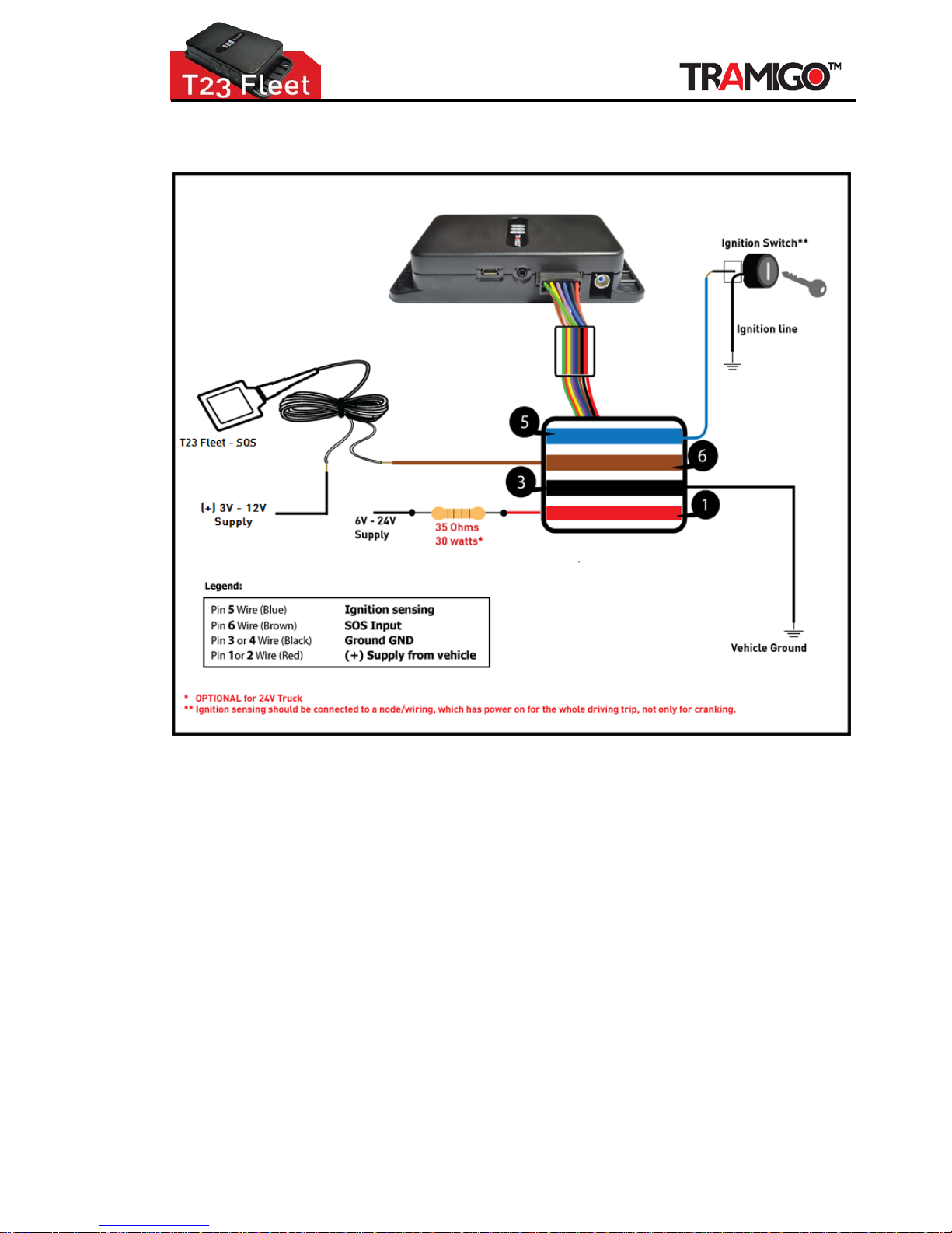
8 Wiring Diagram
Figure 5 – T23 FLEET Ignition Wiring Diagram
Page 20
Installation Guide
© 2007 - 2013 Tramigo™ Ltd. All rights reserved. Under the copyright laws, this manual cannot be reproduced in any form
without the prior written permission of Tramigo™. Page
20
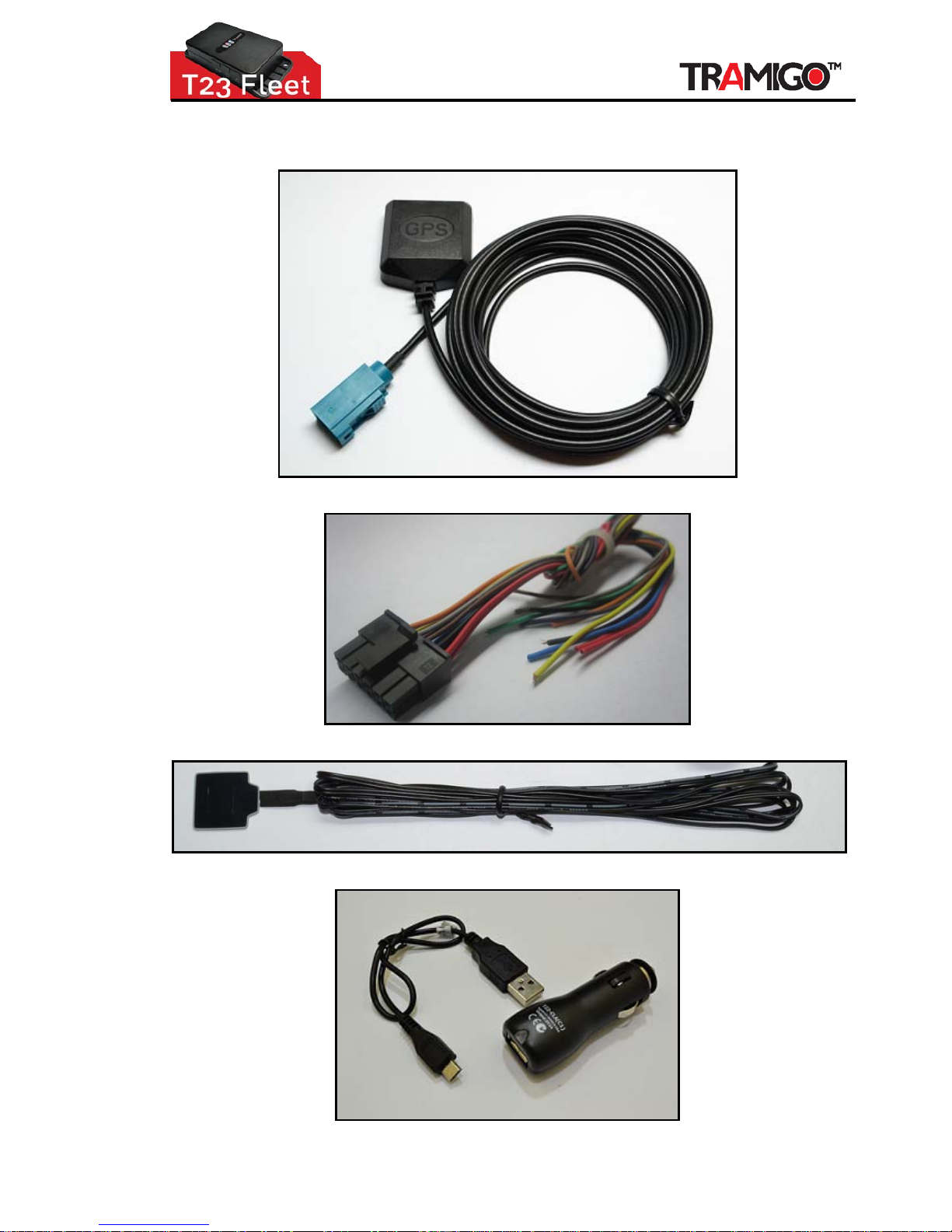
9 T23 FLEET Spare Parts & Order Numbers
Figure 6 - T23 FLEET-GPS (optional)
Figure7 - T23 FLEET-IO
Figure 8- T23 FLEET-SOS (optional)
Figure 9- T23 FLEET-USB + T23 FLEET-CLA (optional)
Page 21
Installation Guide
© 2007 - 2013 Tramigo™ Ltd. All rights reserved. Under the copyright laws, this manual cannot be reproduced in any form
without the prior written permission of Tramigo™. Page
21
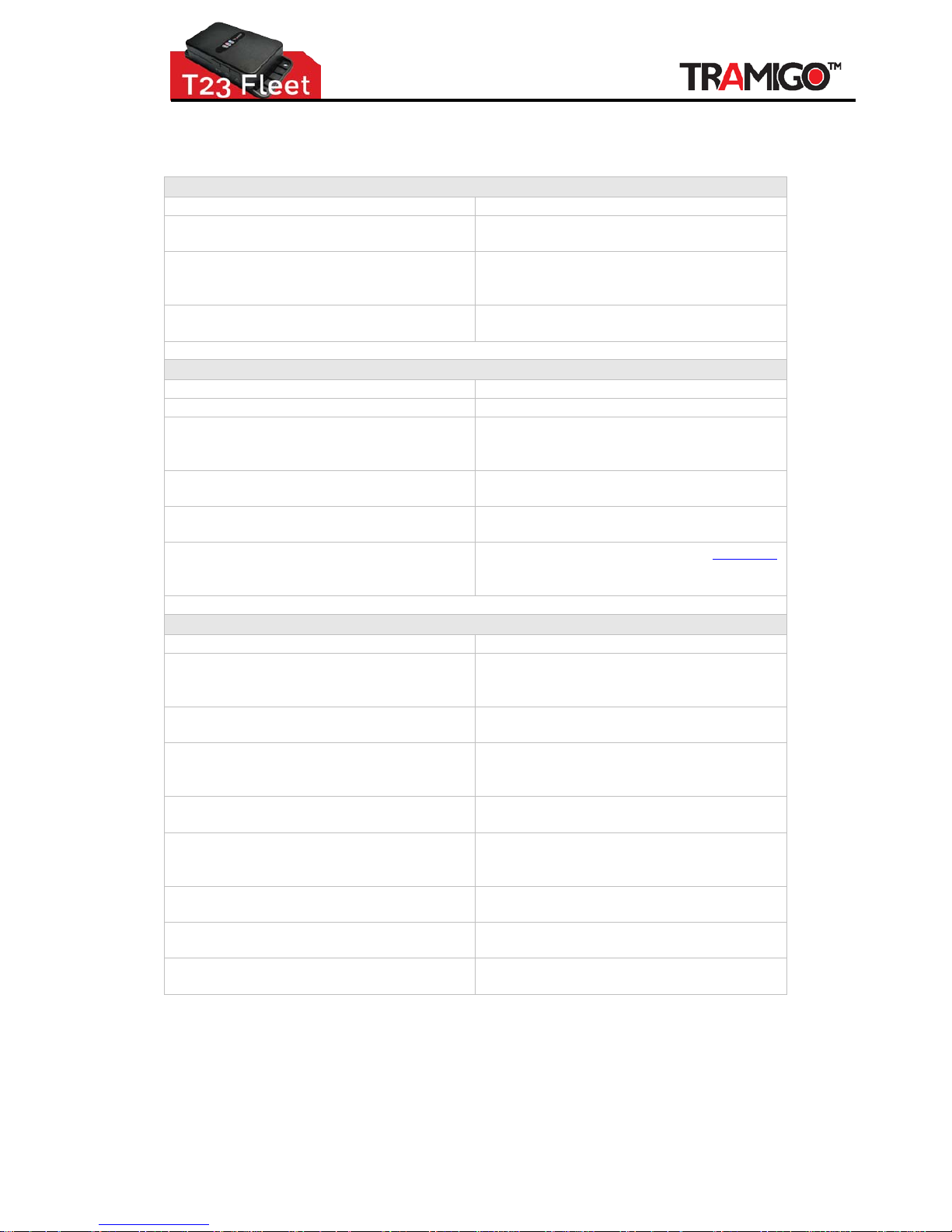
10 Troubleshooting
Problem: Unit does not turn on when the power switch is pressed
Possible Cause:
Resolution:
Power switch was not pressed for 2 seconds
or more
Press power switch longer.
Battery needs charging (sometimes lights will
be very dim)
Recharge battery. If battery is completely
discharged then the Lights will not turn on
for 1.5 hours
Power switch disabled by configuration
Remove and re-insert the battery to turn unit
on.
Problem: Unit does not respond to SMS
Possible Cause:
Resolution:
GSM light is on or flashing Refer to GSM prob l em resolution
GSM Network is slow
Wait for SMS. Some GSM networks slow
down during peak times or when they have
equipment problems.
Unit is sleeping
Wait for unit to wake up or activate the
motion sensor.
User is not authorized Check that the user’s phone number is added
to the user list.
User does not have a high authority for the
command
Check the user’s authority with the LISTUSER
command. T23 FLEET will not respond to
any unauthorized commands.
Problem: GSM light is always ON
Possible Cause:
Resolution:
No GSM signal Check with a mobile phone to see if there is
a signal in the area or try to call the unit to
see if you receive a ring tone.
No SIM card Insert working SIM card. Check through a
phone that the SIM can send SMS messages.
SIM card has expired
Check through a phone that the SIM can
send SMS messages. Replace SIM card if
needed.
SIM has PIN code set
Remove PIN code through a phone by
inserting the SIM and delete the code.
SIM is warped or damaged Inspect SIM, clean the contacts. If re-
inserting does not help try another SIM to
see if it will work.
Roaming not enabled
If you are in a different country your SIM
account must have roaming enabled.
Battery is low (for portable use) Recharge the unit for 5-15 minutes a nd the
GSM will start working.
Unknown problem Remove and re-insert the battery after 1
minute.
Page 22
Installation Guide
© 2007 - 2013 Tramigo™ Ltd. All rights reserved. Under the copyright laws, this manual cannot be reproduced in any form
without the prior written permission of Tramigo™. Page
22
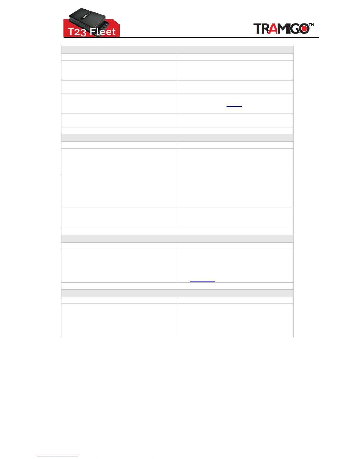
Problem: GSM light is flashing (T23 FLEET fails in sending message)
Possible Cause:
Resolution:
No GSM signal Check with a mobile phone to see if there is
a signal in the area or try to call the unit to
see if you receive a ring tone.
Network busy Wait a few minutes to see if the message
gets through.
Zero balance on pre-paid account Add credit to the account. Unit will recover
on its own or send
BOOT command to
restart the device.
Phone number in user list is incorrect
If you have just added a new user, check
that the phone number is correct.
Problem: GPS light is on (T23 FLEET does not have a current location)
Possible Cause: Resolution:
Unit does not have clear view of the sky Move the unit to a location where the sky is
visible. Tall buildings, trees, heavy rain, car
tinting, can cause problems with the GPS
reception.
Car tinting is blocking the GPS signal Move the unit outside the vehicle – if the
light goes off then the tinting is blocking the
signal. Either change the tinting in the
windshield or install the optional external GPS
antenna outside the vehicle.
Unit has been moved a large distance
without a location fix. Example: on a flight or
train trip.
Remove and re-insert the battery to reset the
location.
Problem: Owner has lost their phone
Possible Cause:
Resolution:
N/A If a backup owner has been defined then use
their phone to add your new number in.
Use OWNER,password to add your new
number and then delete the old number with
the
DELUSER command
Problem: Owner has forgotten their password
Possible Cause:
Resolution:
N/A The owner can send the
RESETSETTINGS
command to set the password back to 0000.
All other settings are also reset as if the unit
is new. The Owner will have to register the
setting and users again.
Page 23
Installation Guide
© 2007 - 2013 Tramigo™ Ltd. All rights reserved. Under the copyright laws, this manual cannot be reproduced in any form
without the prior written permission of Tramigo™. Page
23
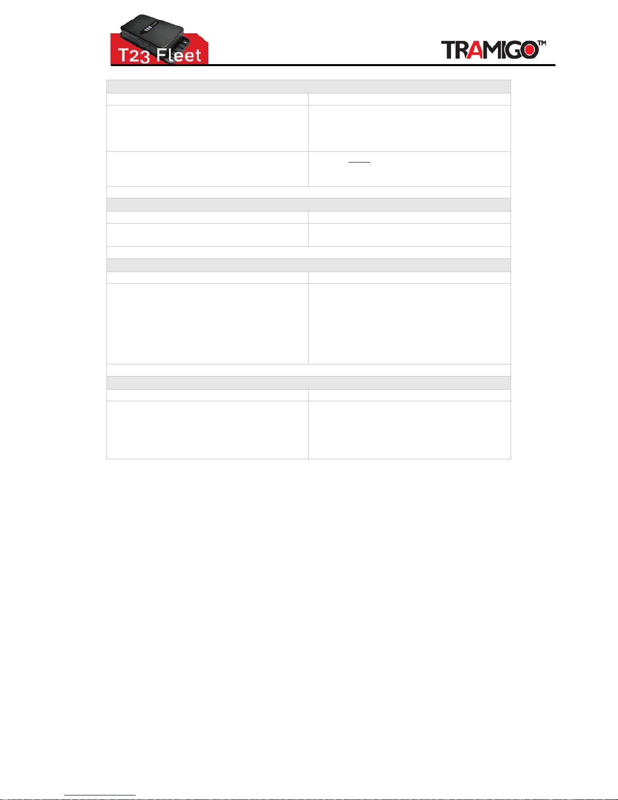
Problem: Time stamp in the SMS reports is wrong
Possible Cause:
Resolution:
T23 FLEET requires a GPS fix to determine
the time zone and connection to the GSM
network to determine the time. Time will
show 00:00 Jan 01 on first use.
Wait for the GPS and GSM lights to go off
then send the unit an SMS to check the time.
GSM Operator time is incorrect Use the TIME command to override the GSM
time. Some GSM operators have problems
with DST and roaming phones.
Problem: Trip end report late and shows long idle time
Possible Cause: Resolution:
Motion detector is detecting movement and
unit thinks trip is still active.
Reduce sensitivity of motion detector, or
locate motion detector in different location.
Problem: Trip reports are recei ved when vehicle is parked
Possible Cause:
Resolution:
Vehicle is parked with a limited view of the
sky so the GPS signa ls are weak and bounce
off the buildings. This can ge ner ate short
trip reports.
Turn off trip reporting when in these
locations.
If you are not interested in short trip reports
Increase the minimum trip distance to 1 km
or higher
Set,MinTripDistance,1000
Problem: Vehicle shows as parked, but its moving
Possible Cause:
Resolution:
Your T23 FLEET will report a state of Parked
when a Trip has not been started which takes
300m, so if a FIND or any other report is
received during this time, it will show the
vehicle as “Parked”.
None. Once a Trip Start is detected, the
vehicle state will change to moving or
stopped
As we constantly strive to improve our products, all spe cifications are subject to change without notice. The information provided
herein is believed to be correct at the time of goi ng to press.
 Loading...