

Page 1
04/2015
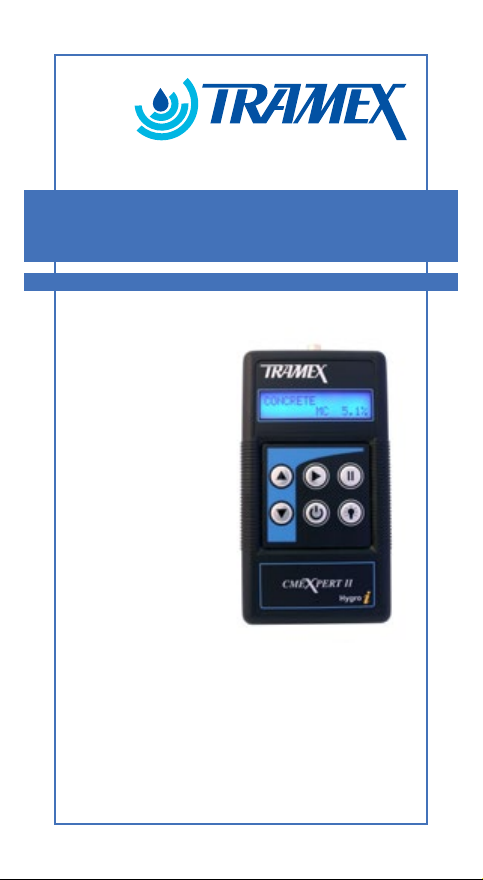
user guide
CMEX II
concrete moisture
meter (Digital)
Page 2

Page 3

USER GUIDE
TABLE OF CONTENTS
Introduction.......................................................................4
How it works...................................................................5-6
Instrument Features........................................................7-8
Operating Instructions.......................................................9
Non-Destructive Measurement Mode .......................10-15
Concrete Scale.............................................................10
CM (Carbide Method) Equivalent Scale......................11
Gypsum Scale..............................................................11
REF (Reference) Scale..................................................11
Calibration .................................................................12
CMEX II Displays.......................................................13
Drying time for concrete oors and screeds............13-14
Testing moisture content in a oor slab.......................14
Pre-testing guidelines..................................................14
Guideline test procedures as per ASTM F2659...........15
Humidity Measurement Mode ..................................16-25
Relative Humidity Measurement................................17
Moisture Testing Guidelines...................................17-23
Hole Liner Instructions ASTM F2170 / BS8201,
8203, 5325...........................................................20-21
Calibration Check Salts..........................................24-25
Wood Pin Meter Mode...............................................26-43
Factors Affecting Moisture Readings..........................27
Wood Flooring ......................................................28-29
Temperature Adjustment Chart..................................30
Humidity and Moisture Content Relationship.............31
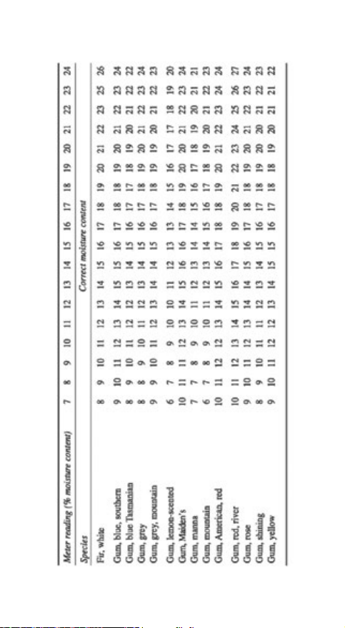
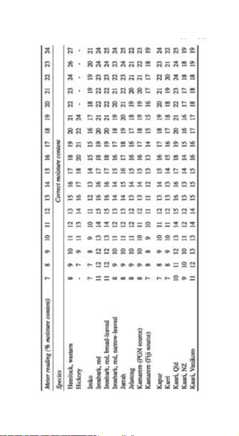
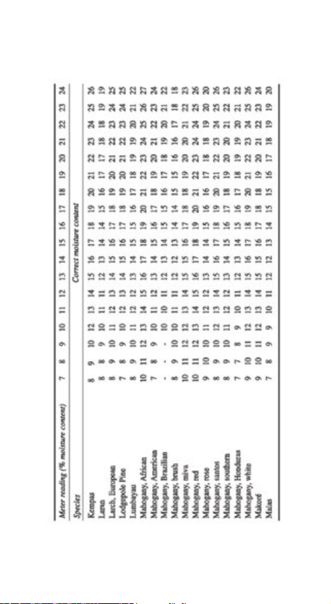
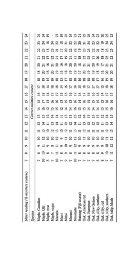
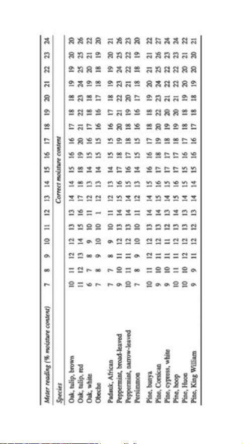
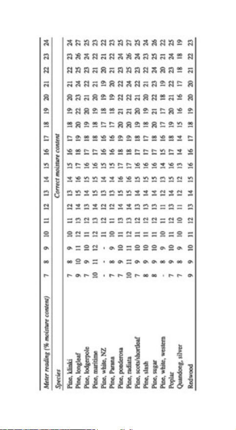
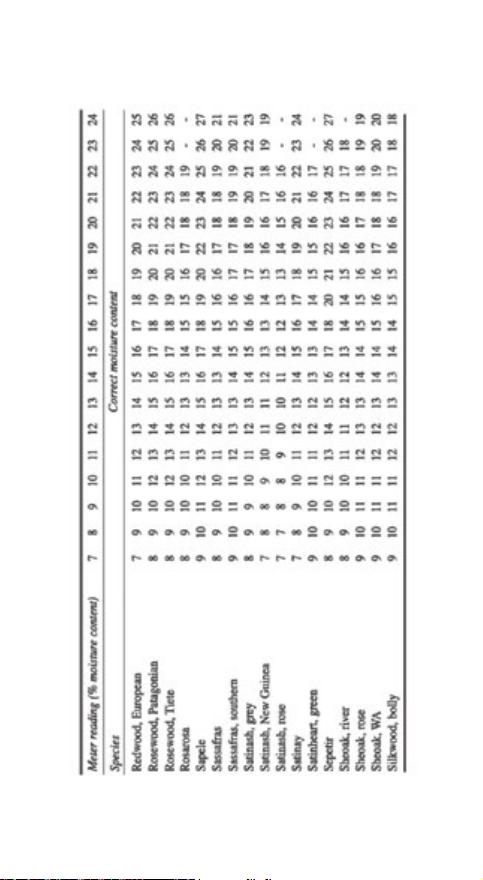
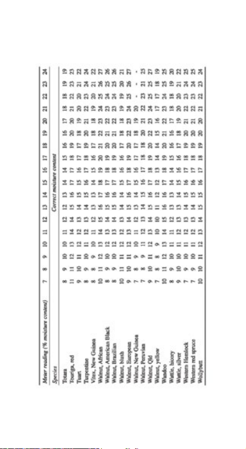
Species Correction Charts......................................32-43
Limitations .......................................................................44
Calibration ......................................................................44
Warranty ............................................................................45
Product Development......................................................46
Safety...............................................................................46
3
Page 4

USER GUIDE
INTRODUCTION
Thank you for selecting the new CMEXpert II instrument,
from Tramex. It has 3 measurement modes.
1. Non-invasive, Non-destructive test (NDT) mode
The CMEXpert II utilises “state of the art”
electronic technology to provide you with an
accurate and easy to use non-invasive instrument
for non-destructive testing (NDT) of Moisture
Content (MC%) in concrete and comparative
readings in gypsum and other oor screeds.
2. Hygro-i probe mode
This enables the CMEXpert II to measure
relative humidity (RH), temperature, dew point
temperature and mixing ratio of the environment
or in a structural material. A structural material
such as a concrete slab can be tested using the insitu method (ASTM F2170) or RH Hood methods
(British Standards BS 8201, 8203, 5325).
3. PIN Probe mode
This enables the CMEXpert II to measure the
percentage moisture content (MC%) of wood. The
CMEXpert II can also be used for wood-based
products.
4
Page 5
USER GUIDE
HOW IT WORKS
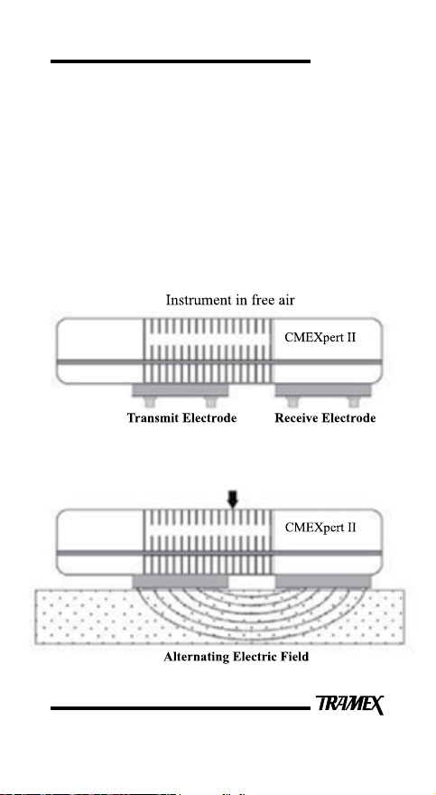
In concrete moisture measurement NDT mode, the
instrument operates on the principle that the electrical
impedance of a material varies with its moisture content.
The electrical impedance is measured by creating a
low frequency alternating electric eld between the
electrodes as illustrated in Figure 1.
Figure 1
The instrument is pressed onto the material surface
with the pins fully compressed to measure/detect the
moisture content.
5
Page 6

USER GUIDE
This eld penetrates the material under test. The very
small alternating current owing through the eld is
inversely proportional to the impedance of the material.
The instrument detects this current, determines its
amplitude and thus derives the moisture value.
In Hygro-i probe mode, the CMEXpert II determines
the capacitance of the RH probe sensor which varies
with the relative humidity of the testing environment.
The CMEXpert II displays this capacitance as percentage
relative humidity (%RH). It also measures temperature
and displays dew-point temperature and mixing ratio.
In Pin probe mode the CMEXpert II is a resistance-type
pin-meter for determining the moisture content of wood
and wood-based products.
6
Page 7
USER GUIDE
INSTRUMENT FEATURES
Your CMEXpert II employs advanced digital technology
to enable the incorporation of the many features listed
below.
● 3 modes of measurement: Non-destructive moisture
measurement, hygrometer and wood pin probe.
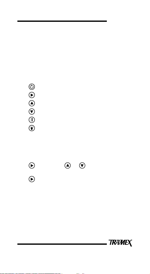
● 6 simple membrane keypad controls:
ON/OFF
SCALE
UP
DOWN
HOLD / AUDIO
BACKLIGHT
● Moisture readings and scale are displayed on a
clear easy to read liquid crystal display (LCD).
● 4 NDT Scales: Concrete, CM Equiv (Carbide
Method equivalent for concrete), Gypsum and a
Ref (Reference) scale. These are selected using the
key and the or keys.
● Wood pin probe mode is selected by using the
key.
● Relative Humidity (RH) readings, probe
temperature, dew point temperature and mixing
ratio are automatically displayed when the
Hygro-i Probe is plugged into the CMEXpert II
(Hygrometer Mode).
7
Page 8
USER GUIDE
● To conserve battery life, the instrument automatically
powers OFF after 10 minutes of inactivity or when
the key is pressed. If a key is pressed the
power off time will be extended for an additional ten
minutes.
● Backlit display allows the display to be easily read
in poor light conditions. This is enabled by pressing
the key. The backlight stays on for a period of
time set.
● Backlight display time. To adjust the backlight
display time, press the and keys together.
Then scroll with the key from 10 – 60 seconds.
(If the key is pressed, you will enter language
choice settings.) When time is chosen select
key to conrm and return to scale mode. (Longer
backlight timeouts will reduce the battery life.)
● Language display adjustment. To adjust the language
display, press the and keys together. Then
scroll with the key through the language library.
(If the key is pressed, you will enter the backlight
time settings.) When language is chosen select
key to conrm and return to scale mode.
● HOLD freezes reading to facilitate ease of
recording readings. When the CMEXpert II is in
HOLD mode, ‘H’ will ash on the display. If HOLD
was selected prior to the CMEXpert II automatically
powering off, the frozen display reading is digitally
memorized and restored next time ON is selected.
● When the battery requires replacement a LOW
BATTERY message is shown on the LCD.
8
Page 9
USER GUIDE
OPERATING INSTRUCTIONS
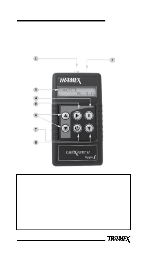
The instrument face with brief notes on the push button
controls and LCD is shown below.
Figure 2
1 = Phono socket for Wood Probes.
2 = Hygro-i Probe Socket (automatic hygrometer mode when
plugged in).
3 = Backlit display.
4 = Hold Key
5 = Scale Key.
6 = UP / DOWN Keys
7 = ON / OFF Key 10 minute switch off
8 = Light Key.
9
Page 10
USER GUIDE
NON-DESTRUCTIVE MEASUREMENT MODE
1. Press the key to power up. With no Hygro-i
probe or pin probe connected the last used scale
will be displayed on the LCD. Press key again
to power off.
2. To change mode, press key to select the Concrete,
Pin Probe or the comparative material scales. The
comparative material scales consist of CM Equiv.,
Gypsum and Ref. Select the CM Equiv., Gypsum or
Ref. scale using the key or key.
3. Press your CMEXpert II directly onto the surface
of the material being tested ensuring that all the
electrode spring-loaded pins are fully compressed.
Concrete Scale
When the Concrete scale is selected the moisture content
(MC) is shown on the right-hand side of the bottom line of
the display. The moisture content (MC) is displayed 0 to
6.9% on the CMEXpert II display. Readings on a concrete
oor slab obtained on this scale indicate moisture content
and should not be confused with Pounds (lbs) emission or
any other unit of measurement obtained by other moisture
testing methods or meters. It should also be noted that
there seems to be no linear correlation between moisture
content measurements and lbs emission measurements as
obtained using calcium chloride testing methods.
10
Page 11

USER GUIDE
CM Equivalent Scale (for concrete)
The CMEXpert II gives readings of 0 to 4.3 on the CM
Equivalent Scale. These are approximated equivalent
readings to the carbide test method for concrete.
Gypsum Scale
The CMEXpert II gives moisture content readings from 0
to 12 (comparative) on Gypsum and Anhydrite screeds.
REF Scale
For the Reference scale the readings are comparative
from 0 to 99. A visual indication is also given by the bar
display on the bottom line of the LCD.
The readings on the reference scale are not to be interpreted
as a measurement of percentage moisture content (%MC)
or relative humidity (RH). It is not a relative humidity
reading and it does not have any linear correlation with
Relative Humidity measurements. This scale should
be regarded as a comparative or qualitative scale only.
This reference scale is included to facilitate comparative
testing of different areas where direct contact with the bare
concrete surfaces may not be possible due to some form of
very thin coating or covering on the concrete, or additive
in the concrete that could inuence the readings. This scale
is not suitable for reading through thicker oor coverings
such as wood laminates etc. Readings from the reference
scale are comparative only and of help in identifying areas
with moisture problems.
11
Page 12

USER GUIDE
Calibration
For regular on-site assessment of your CMEXpert II in
moisture measurement mode, a calibration-check plate is
available from the suppliers of your CMEXpert II. Should
it be found that readings are outside the set tolerances, it
is recommended that the CMEXpert II be returned for recalibration. Calibration adjustments should not be carried
out by anyone other than Tramex or their authorized
service provider who will issue a calibration certicate on
completion.
Requirements for quality management and validation
procedures, such as ISO 9000 and National Standards,
have increased the need for regulation and verication
of measuring and test instruments. It is therefore
recommended that calibration of the CMEXpert II should
be checked and certied in accordance with the standards
and/or protocols laid down by your industry (usually on
an annual basis) by an authorised test provider. The name
of your nearest test provider and estimate of costs are
available on request.
12
Page 13
USER GUIDE
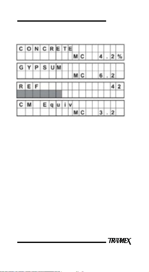
Typical CMEXpert II Displays
Drying time for concrete oors and screeds
Concrete oors and screeds must be allowed to dry to an
adequate level before the installation of sheet material,
tile, wood or coating. Manufacturers of such systems
generally require moisture testing to be performed before
installation on a oor slab. Moisture content measurement
is one such method. Excessive moisture in or permeating
from a oor covering or coating can cause failures such
as condensation, blistering, delaminating, movement and
general deterioration of the nished ooring/coating.
There is also a risk of promoting microbial growth. No
exact period can be specied for the drying of such oors
to reach acceptable moisture content, as this is affected by
temperature and humidity within the building as well as
concrete curing times and other factors. Typically a period
of 1 month per inch (25mm) depth of concrete or sand/
cement screed is often quoted. Longer periods may be
required in areas of high humidity or low temperature.
13
Page 14

USER GUIDE
During the drying period and prior to applying the oor
covering, the oor should be regularly checked to monitor
moisture content.
Testing for moisture content in a oor slab
Pre-test conditioning and preparation
For best and most accurate results, tests should be carried
out after the internal conditions of the building in which
the slab is located have been at normal service temperature
and humidity for at least 48 hours. All articial heating or
drying equipment should be turned off at least 96 hours
before nal readings are attempted, otherwise results may
not accurately reect the amount of moisture present or
moisture movement in the slab during normal operating
conditions. Prior to testing, the actual test area should be
clean and free of foreign substances.
Pre-testing guidelines
Where covered oor slabs are being tested, all covering
materials, adhesive residue, curing compounds, sealers,
paints, etc., shall be removed to expose a test area of clean
bare concrete. For removal of any existing ooring or
adhesives, strictly observe all the appropriate safety and
health practices relevant to cleaning and removal of these
types of materials. Removal of covering materials and
cleaning, if required, should take place a minimum of 48
hours prior to testing. Use of water based cleaning methods
that could lead to elevated surface and/or sub-surface
moisture levels in the oor slab are not recommended, and
the testing after such treatment could result in elevated
readings. No visible water in liquid form should be present
on the concrete at the time of testing. Avoid testing in
locations subject to direct sunlight or sources of heat. Use
of articial aids for accelerated drying of concrete is not
recommended. If they are being used it is recommended
they should be turned off at least four days before taking
nal readings.
14
Page 15

USER GUIDE
Guideline test procedures as per ASTM F2659
1. Remove any dust or foreign matter from the
CMEXpert II electrodes before commencing tests.
Make sure that the oor slab being tested is clean and
bare and free from dust, dirt or standing water.
2. Push the ON button and press the instrument directly
onto the surface of the material being tested ensuring
that all of the electrode spring loaded pins are fully
compressed. Read the moisture measurement from
the appropriate scale of the display.
3. On a rough surface, take a number of readings in
close proximity to one another such as 3 to 5 readings
within an area of 1 ft
2
(929cm2) at each location. If
the readings vary, always use the one with the highest
value.
4. Perform at least eight tests for the rst 1000ft
2
(100m
) and at least ve additional tests for each
additional 1000ft
2
(100m2). Include test locations in
2
the centre of the oor and within 3ft (1m) of each
exterior wall.
15
Page 16
USER GUIDE
HUMIDITY MEASUREMENT MODE
The Hygro-i Probe utilises state of the art electronic
technology to provide an "easy to use" and accurate method
for measuring relative humidity, mixing ratio, temperature
and dew point in a wide range of applications such as:
● Heating, ventilation and air conditioning (HVAC)
systems.
● Environmental and building monitoring.
● Building inspection.
● Flooring (including in-situ method as per ASTM
F2170 and the in-situ and hood methods as per
British Standards BS 8201, 8203, 5325.)
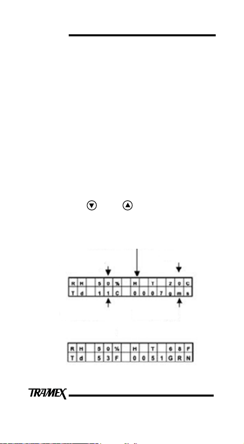
A typical CMEXpert II display with the Hygro-i Probe is
shown below. When the Hygro-i Probe is plugged into the
CMEXpert II, the or key can be used for changing
the temperature between ˚C and ˚F and the mixing ratio
between g/kg and grains/lb.
Flashing "H" in Hold mode
Relative Humidity
T˚C
Dew-piont (Td)˚C
IMPERIAL
16
Mixing Ratio g/kg
Page 17

USER GUIDE
RELATIVE HUMIDITY MEASUREMENT
There are two International Standard methods of relative
humidity measurement in ooring that can be carried out
with the CMEXpert II with the Hygro-i probe attached:
(a) In-situ (below the surface of the slab) ASTM F2170
and BS 8201, 8203, 5325.
(b) RH Hood (on the surface of the oor slab) BS 8201,
8203, 5325.
(a) In-situ Relative Humidity Test Method – ASTM
F2170 Guidelines.
2
Perform 3 per 1000ft
Holes must be drilled dry and perpendicular (90˚), do not
(100m2) and 1 per next 1000ft2
use water for cooling or lubrication.
When drying is from the top only, it is recommended
that the hole should be drilled to approx 40% of the slab
thickness.
When drying is from both sides, it is recommended that
the slab should be drilled to approx 20% of slab thickness.
A hole cleaning brush is often required to ensure the drilled
hole is free from any loose particles. A vacuum should also
be used to ensure the drilled hole is free from any dust.
The user should always refer to ASTM or national
standard guideliness for denitive and current procedure
and specications.
17
Page 18

USER GUIDE
MOISTURE TESTING GUIDELINES
When performing moisture testing of concrete it is
important to get the most accurate and most useful data
from the tests. For this reason Tramex recommend a
two-pronged approach. The rst step is to carry out a
non-invasive moisture test with the Tramex CME4 or
CMEX. This measures the top section of the concrete
slab and gives an average percentage moisture content of
the footprint area of the meter. These readings should be
used to determine where and how in-situ relative humidity
(RH) testing is performed. If the CME4 / CMEX reading
is above 5%, Tramex recommend that the test holes are
drilled, sleeves are placed and capped and left for a period
of 72 hours. The probes are then inserted. A suitable
equilibration time is allowed before taking readings (see
below). If the CME4 / CMEX reading is at or below 5%,
the testing can be carried out either by placing sleeves and
leaving 72 hours as above or inserting probes immediately
after sleeves have been placed and taking readings after
72 hours.
The above recommendations are based on the requirements
to prolong the life of the RH probe and to increase the
accuracy of the test. Tramex recommend that the RH
probes are not left in-situ for prolonged periods of time
when RH values are above 93%. With the Tramex system
it is possible to remove the probe and seal the sleeve for
future testing, thus giving a more reliable and accurate test.
18
Page 19
USER GUIDE
Equalibration Time:
Allow at least 30 minutes for probe to reach
temperature equilibrium before measuring relative
humidity. It is vitally important that the concrete is
at the same temperature as the probe.
Even a slight difference in temperature will produce
a signicant error in relative humidity measurement.
Check that meter readings do not drift by more than
1% RH over a 5 minute period.
The sensor in the Hygro-i probe may take longer to
recover if exposed to readings above 93% and can be
damaged by prolonged exposure to high humidity.
19
Page 20
USER GUIDE
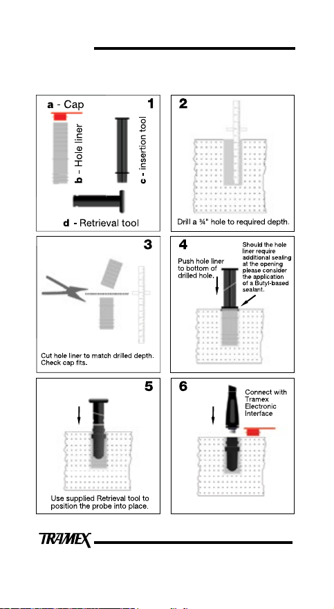
HOLE LINER INSTRUCTION ASTM F2170
20
Page 21

RH Hood Method
USER GUIDE
Dust Cap
Hygro-i probe
RH Hood
Floor Slab
Place the probe in to RH
Hood and cover with Dust
Cap if necessary.
Floor Slab
Connect Tramex CMEX II,
WME or MRH III or to take
readings
Seal the hood to
surface with butyl
tape provided
Floor Slab
For the best results ensure
surface is cleaned of any
foreign materials that could
affect a sealed test air space.
Sealed test
air space
Floor Slab
Please refer to the period of
time as specied by the
standard being followed for
the duration of test.
Calibration
Salt
A probe calibration check is
recommended within 30 days
before the test.
21
Page 22

USER GUIDE
(b) On surface RH tests (RH hood method)
The Tramex RH Hood can be used to perform testing to
British Standards BS 8201, 8203, 5325. The following
components are required to perform a RH Hood test:
CMEXpert II, Insulated hood (RHIH), Hygro-i probe and
interface. The Tramex WME or MRH III can also be used
with the RH Hood.
Pre test guidelines.
The CMEXpert II should be used rst in non invasive
mode to give an overall moisture condition of the oor
slab. These readings will determine where to position the
insulated hood. Careful consideration should be given
to location of test site. The hood should not be located
in direct sunlight or in an area which can be accidently
disturbed. The oor slab surface should be cleaned of any
foreign materials and swept clean of any dust or loose
materials that could affect a proper seal between the hood
and surface of the oor. The oor should be prepared as
specied in the relevant standard.
1. Using a double-sided preformed adhesive/butyl tape,
seal the insulated RH hood to the concrete surface.
2. Insert Hygro-i probe into the hood using the
insertion/ retrieval tool.
The sensor in the Hygro-i probe may take longer to
recover if exposed to readings above 93% and can
be damaged by prolonged exposure to high humidity.
3. Please refer to the period of time as specied by the
standard being followed for the duration of the test.
The user should always refer to national standard
guidelines for denitive and current procedures and
specications.
22
Page 23

USER GUIDE
4. When the time period has elapsed, check that meter
readings do not drift by more than 1% RH over
a 5 min period. Ensure the readings correspond
with the oor covering/adhesive manufacturers
or national standard recommendations before
applying oor covering. e.g. British standards code
of practice BS8203 suggests that a concrete oor
should be sufciently dry to allow installation of a
resilient oor covering when the measured relative
humidity falls to 75% or lower using the insulated
impermeable box/hood method as specied in the
above standard.
Use of articial aids for accelerated drying of
concrete is not recommended. If they are being
used it is recommended that they be turned off at
least 96 hours before taking nal readings.
23
Page 24

USER GUIDE
CALIBRATION CHECK SALTS
A saturated salt solution is the most suitable method for
on-site testing of humidity sensors. The advantage of the
on-site salt calibration check is that the user can check that
the sensors are performing satisfactorily without having
the need to send the sensors to a testing laboratory, which
can be expensive and time consuming. The sensors can
be checked at a time that is convenient to the user, which
means no down time for your equipment. ASTM F2170
requires that humidity probes are checked and readings
recorded by the user within 30 days before use. This
check can be achieved with a 75% RH saturated Sodium
Chloride (NaCI) solution.
Conditioning of the NaCI calibration check solution
and test procedure.
As Relative Humidity (RH) is dened as the ratio of the
partial vapor pressure in air to the saturated vapor pressure
at a given temperature, it is important to understand that
RH strongly depends on temperature. Therefore, it is
essential to keep humidity sensors at the same temperature
as the air in which the relative humidity is to be measured.
When testing RH probes in a calibration check-salt
chamber, it is necessary for the internal temperature of the
salt chamber to be the same as that of the surrounding air
and also the RH probe sensor. This can be achieved by
removing the cap and exposing the salt-check solution to
ambient conditions. The temperature can be checked with
the use of an infra red thermometer. When the probe and
solution are showing equal temperature insert the probe
into the solution.
24
Page 25

USER GUIDE
The test can be ended when RH% readings do not drift
by more than 1% RH over a 5 minute period within the
acceptable +/- 2% tolerance of the nominal 75% relative
humidity. A temperature difference of +/- 1°C (1.8°F) can
cause an error of up to +/-3 to 5% at 50% RH and +/-6%
at 97% RH readings. Please note any further handling of
the salt chamber can cause a heating effect so handle the
salt chamber as little as possible.
Due consideration must also be given to the test site, do
not perform in direct sunlight or close to sources of heat
eg. heaters or spotlights.
Temperature stability is extremely important for the
duration of the test.
Calibration check salts do not have an expiry date and have
unlimited usage when cared for in the correct manner.
Do check the seal inside chamber is exposing as much of
the vent as possible and that there is a mix of salt and
water and no caking of salt to side walls of chamber.
Humidity probes exposed to conditions outside normal
range, especially high humidity may temporarily offset
the RH reading. After return to normal ambient condition
it will slowly return towards calibration state by itself.
Prolonged exposure to extreme conditions may accelerate
ageing.
For further information please refer to the latest calibration
check salt instructions which are supplied separately.
25
Page 26
USER GUIDE
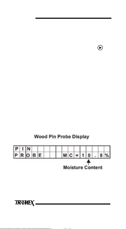
PIN PROBE (WOOD PIN-METER) MODE
This mode is activated by plugging one of the optional
Wood Electrodes into the socket at the top of the
instrument and selecting Pin Probe using the key.
In pin probe mode the CMEXpert II works on the principle
of electrical resistance. When the electrode pins are
pressed or driven into the wood, the electrical resistance
between the electrodes is measured and indicated on the
digital display. If the wood is dry, the resistance is very
high. The higher the moisture content, the lower the
resistance. This resistance is accurately measured by the
instrument, which translates it into percentage moisture
content for wood. The CMEXpert II gives moisture
readings from 7% to approximately 50%. It should be
noted that readings above 27% (nominal value of the ber
saturation point) are indicative only. Readings below 7%
will be displayed as LO.
26
Page 27

USER GUIDE
Factors Affecting Moisture Readings
The readings of all moisture meters are influenced by
the characteristics of different species of wood as well as
temperature and other factors listed below:
Species
Different species of wood can vary in density and
conductivity, which can have an effect on the electrical
resistance of the wood. This can influence meter readings
for the same moisture content and can also apply to similar
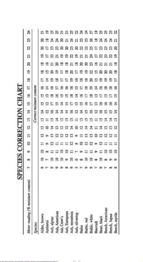
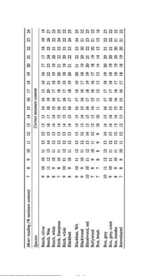
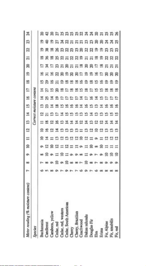
species from different origins. A species adjustment table
is provided on page 32 to 43.
Temperature
Meter readings can be affected by wood temperature.
The Wood Probe is calibrated at 20°C (68°F). At wood
temperatures above 20°C (68°F), the meter readings are
higher and at wood temperatures below 20°C (68°F) the
meter readings are lower. A temperature adjustment chart
is provided on page 30.
Chemical treatment or contamination
Readings may be affected by certain flame retardants,
preservatives, aluminium paint and by contamination by
salt water. Treat all readings on such wood as indicative
readings only.
Surface Moisture
Surface moisture due to wetting or condensation can
affect readings when uninsulated pins are used. It is
recommended that insulated pins such as SP-52 are used
in conjunction with HA-22 Hammer Action electrode. As
the pins are driven into the wood, readings can be taken at
different depths, unaffected by moisture on the surface.
27
Page 28

USER GUIDE
WOOD FLOORING
Excess moisture in wood flooring can cause major
problems. For instance, if installed with excess moisture,
the wood can subsequently shrink, leading to job failure.
If a wood floor (solid or engineered) is installed above wet
concrete the wood can absorb moisture emitting from the
concrete, causing the wood to swell and buckle and even
cause structural damage to the building.
Your CMEXpert II is used to measure the moisture
conditions in the concrete and when in Pin Probe mode
can be used to measure the moisture content of the wood
floor to ensure it meets specification.
Testing wood and wood products
a. When testing wood, power-on, insert wood probe
into phono-socket at the top of the CMEXpert II and
select Pin Probe Mode using the key.
b. When a wood probe is inserted the moisture content
(MC) in percent is shown on the right-hand side of
the bottom line of the display.
c. If possible, always take readings with the pins
parallel to the direction of the wood grain.
d. Calibration tests are based on Douglas fir, which has
a published specific gravity (SG) of 0.50.
e. Acceptable levels of moisture content depend on
climatic conditions and we advise you check the
levels acceptable in your area. The Table on page
31 shows the approximate relationship between the
ambient relative humidity and equilibrium moisture
content in woods.
28
Page 29

USER GUIDE
f. The following moisture content levels are often
quoted in the wood industry and should be used as a
guide only. Please contact industry associations and
manufacturers for their specifications.
● Furniture and Interior wood: Readings below 7% in
locations of low relative humidity and 10% to 12%
may be acceptable where the relative humidity is
higher.
● Exterior wood: 10% to 15% depending on local
humidity levels. Generally, wood with moisture
content in excess of 23% to 25% is susceptible to rot.
● Wood moisture content in excess of 18% to 20% may
provide an environment for termite and woodboring
insects to thrive and multiply. Wood at these high
levels can also support mold and biological growth.
● Wood at about 27% to 28% moisture content is
considered to have reached fiber saturation point.
g. Avoid taking readings on wood from the top of
a stack stored outside as these may be affected by
surface moisture from recent rain.
h. When taking readings in chemically treated wood,
it is advisable to allow for possible effects that the
treatment may have on readings.
29
Page 30
USER GUIDE
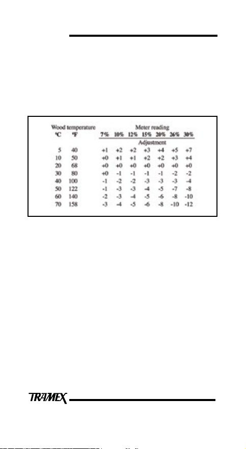
Temperature Adjustment Chart
The Pin Probe has been calibrated on wood at an ambient
temperature of 20°C ( 68°F). When measuring moisture in
wood at a different temperature , the following temperature
adjustment needs to be applied. (Figures rounded to the
nearest whole number)
Example 1:
If meter reads 15% and temperature of wood is
10°C (50°F), actual moisture content is 17%.
i.e.15% + 2% = 17%
Example 2:
If meter reads 15% and temperature of wood is 50°C
(122°F), the actual moisture content is 11%.
i.e.15% - 4% = 11%
Combined Species / Temperature Correction
Example 1:
If meter gives reading 15% on a sample of Sitka Spruce and the
wood temperature is 40°C, the correction is as follows:
Species correction @15% = 16%
Temperature correction @ 40°C = - 3%
Corrected reading: 13%.
Example 2:
If meter gives reading 24% on sample of Teak and the wood
temperature is 10°C, the correction is as follows:
Species correction @24% = 20%
Temperature correction @ 10°C = + 2%
Corrected reading: 22%.
30
Page 31
USER GUIDE
Humidity and Moisture Content Relationship
The table below shows the approximate relationship
between relative humidity (RH) and equilibrium moisture
content (EMC) of some woods. (These gures are
approximate values and may vary for different species.)
Table 1. Approx. relationship between RH and EMC
Relative Humidity Wood MC %
10 % 3 to 5
20 % 5 to 6
30 % 6 to 8
40 % 8 to 10
50 % 10 to 11
60 % 11 to 13
70 % 13 to 15
80 % 15 to 18
90 % 18 to 23
100 % 23 +
31
3233343536373839404142
Page 32
Page 33
Page 34
Page 35
Page 36
Page 37
Page 38
Page 39
Page 40
Page 41
Page 42

Page 43
43
Page 44

USER GUIDE
LIMITATIONS
The CMEXpert II will not detect or measure moisture
through any electrically conductive materials including
metal sheeting or cladding, many types of black EPDM
rubber or wet surfaces. The CMEXpert II is not suited
for taking comparative readings in the concrete substrate
through thick oor coverings such as wood.
CALIBRATION
For regular on-site assessment of your CMEXpert II in
moisture measurement mode, a calibration-check plate is
available from the suppliers of your CMEXpert II. Should
it be found that readings are outside the set tolerances, it
is recommended that the CMEXpert II be returned for recalibration. Calibration adjustments should not be carried
out by anyone other than Tramex or their authorised
service provider who will issue a calibration certicate on
completion. Requirements for quality management and
validation procedures, such as ISO 9001, have increased
the need for regulation and verication of measuring
and test instruments. It is therefore recommended that
calibration of the CMEXpert II should be checked and
certied in accordance with the standards and/or protocols
laid down by your industry (usually on an annual basis) by
an authorized test provider. The name of your nearest test
provider and estimate of cost is available on request.
44
Page 45

USER GUIDE
WARRANTY
Tramex warrants that this instrument will be free from
defects and faulty workmanship for a period of one year
from date of rst purchase. If a fault develops during the
warranty period, Tramex will, at its absolute discretion,
either repair the defective product without charge for
the parts and labour, or will provide a replacement in
exchange for the defective product returned to Tramex
Ltd. This warranty shall not apply to any defect, failure or
damage caused by improper use or improper or inadequate
maintenance and care.
In no event shall Tramex, its agents or distributors be
liable to the customer or any other person, company or
organisation for any special, indirect, or consequential
loss or damage of any type whatsoever (including,
without limitation, loss of business, revenue, prots,
data, savings or goodwill), whether occasioned by the
act, breach, omission, default, or negligence of Tramex
Ltd., whether or not foreseeable, arising howsoever out
of or in connection with the sale of this product including
arising out of breach of contract, tort, misrepresentation or
arising from statute or indemnity. Without prejudice to the
above, all other warranties, representations and conditions
whether made orally or implied by circumstances, custom,
contract, equity, statute or common law are hereby
excluded, including all terms implied by Section 13, 14
and 15 of the Sale of Goods Act 1893 and Sale of Goods
and Supply of Services Act 1980.
45
Page 46

USER GUIDE
WARRANTY CLAIMS
A defective product should be returned shipping pre
paid, with full description of defect to your supplier or to
Tramex at address shown on the back of this guide.
PRODUCT DEVELOPMENT
It is the policy of Tramex to continually improve and
update all its products. We therefore reserve the right to
alter the specication or design of this instrument without
prior notice.
SAFETY
This Users Guide does not purport to address the safety
concerns, if any, associated with this instrument or its
use. It is the responsibility of the user of this instrument
to establish appropriate safety and health practices and
determine the applicability of regulatory limitations prior
to use.
46
Page 47

 Loading...