

Page 1
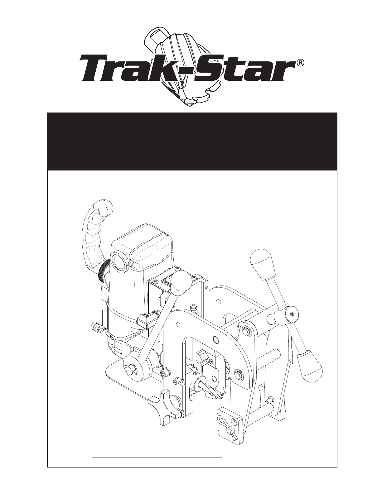
BD17
ELECTRIC BONDING &
TRANSDUCER DRILL
operator’s manual
COVERS PART NUMBERS 0017102, 0017202, 0017302 & 0017109
Serial #:
Date:
OMBD171215 Printed in U.S.A.
Page 2
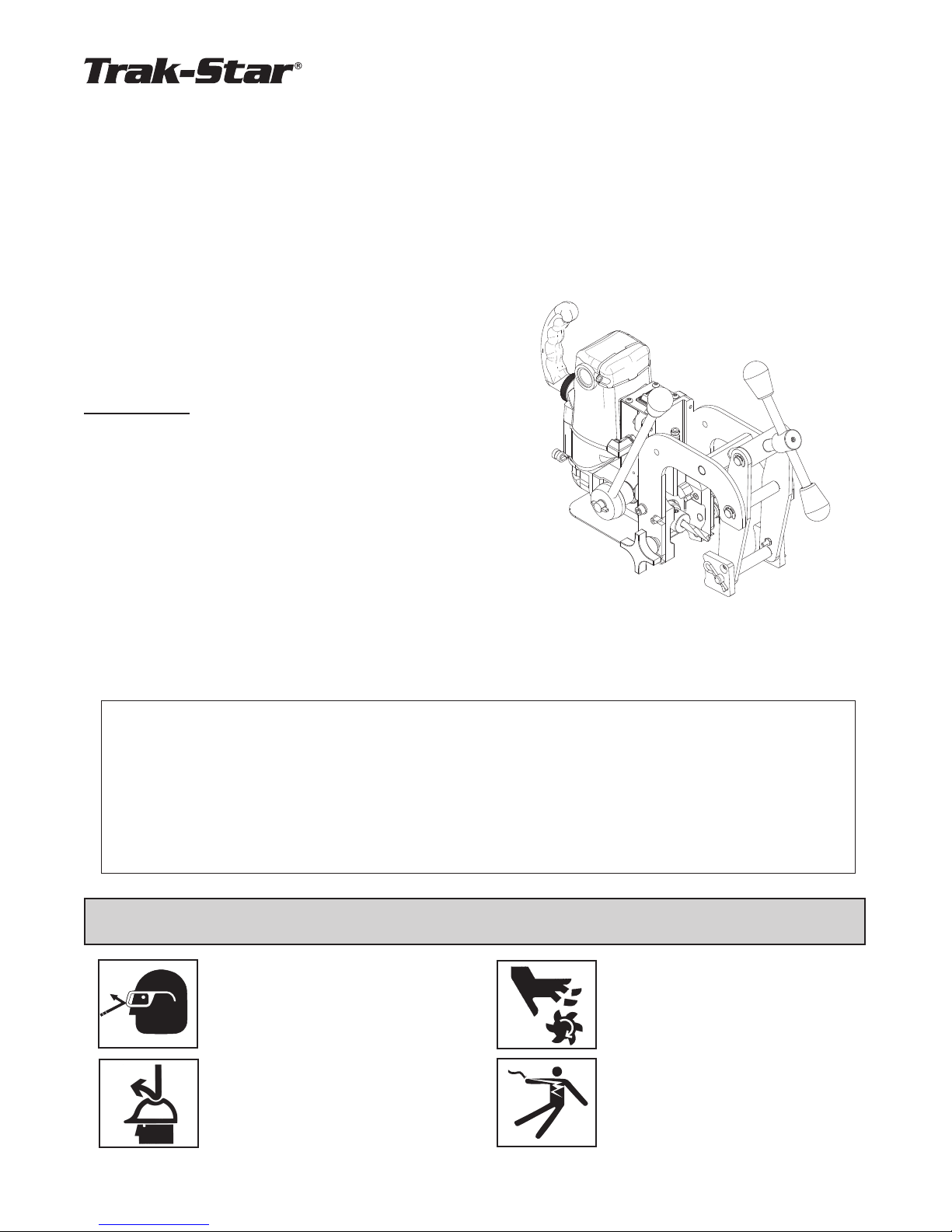
BD17 Electric Bonding Drill & BD17 Transducer Drill
Welcome to Trak-Star
Congratulations on your purchase of the Trak-Star® Drill. Your model is designed to produce
superior holes quickly and efciently. Through constant innovation and development, Trak-Star® is committed
to provide you with hole-producing tools and products that lead the industrial world.
Before attempting to operate your new Trak-Star® Drill, please read all instructions rst. These include the
Operators Manual and Warning Label on the unit itself. With proper use, care, and maintenance, your model will
provide you with years of effective hole drilling performance. Once again, thank you for selecting our product
and welcome to Trak-Star®.
0017102 - BD17 120 volt, Electric Bonding Drill
0017202 - BD17 230 volt, Electric Bonding Drill, U.S. Plug
0017302 - BD17 230 volt, Electric Bonding Drill, Type I Plug
0017109 - BD17 120 volt, Transducer Drill
Specications
Cutter Type...........................3/8" Flatted Shank Bonding Drill
Hole Diameter Capacity
Bonding Drill............9/32", 8mm, 3/8" &13/32"
Transducer...............13/32"
Depth of Cut.........................3/4"/19mm
Motor....................................120V, 7.2A, 450 RPM
230V, 3.6A, 450 RPM
Electrical.............................. 120V, 50/60 Hz, 8A, 960W
230V, 50/60Hz, 4A, 920W
Feed System........................Manual Quill Feed
Net Weight
Bonding Drill............26.5 lbs.
Transducer...............28.5 lbs.
®
Welcome to Trak-Star 2
Important Safety Instructions 3-4
Installing / Removing Bonding Bit 5
Clamping Procedures 6
Pressurized Coolant System 7
Operating Instructions 8
Breakdown & Parts List 9
SAFETY FIRST
Always wear eye protection while
using cutting tools, or in the vicinity of cutting.
CAUTION! The slug is ejected
at the end of the cut. Do not aim
cutter or arbor so that ejected
slug may hit someone around, or
below you.
InDeX
Clamp Assembly Breakdown 10
Transducer Drill Adjustments 10
Motor Diagram & Parts List 11
Quill / Arbor Assembly Breakdown 12
Control Panel Breakdown 13
Transducer Drill Sizing Chart 13
Rail Shoe Data 14
Factory Authorized Repair Centers 16
CAUTION! Cutters are sharp.
Wear gloves when installing or
removing cutter from arbor. Do
not grab a rotating cutter.
CAUTION! To prevent electric
shock, do not use power tools
near wet areas, or where power
tool may become wet.
2
Page 3

Important Safety Instructions
WARNING: Read and understand all instructions. Failure to follow all instructions listed below,
may result in electrical shock, fire and/or serious personal injury.
Work Area
Keep your work area clean and well lit. Cluttered benches and
dark areas invite accidents.
Do not operate power tools in explosive atmospheres, such as
in the presence of flammable liquids, gases or dust. Power tools
create sparks which may ignite the dust or fumes.
Keep bystanders, children, and visitors away while operating a
power tool. Distractions can cause you to loose control.
Electrical Safety
Grounded tools must be plugged into an outlet properly installed and grounded in accordance with all codes and ordianaces. Never remove the ground prong or modify the plug in
any way. Do not us any adapter plugs. Check with a qualified
electrician if you are in doubt as to whether the outlet is properly grounded. If the tools should electrically malfunction or break-
down, grounding is provides a low resistance path to carry electricity
away from the user.
Avoid body contact with grounded surfaces such as pipes,
radiators, ranges and refrigerators. There is an increased risk of
electric shock if your body is grounded.
Don’t expose power tools to rain or wet conditions. Water entering a power tool will increase the risk of electric shock.
Use safety equipment. Always wear eye production. Dust
mask, non-skid safety shoes, hard hat, or hearing protection
must be used for appropriate conditions.
Always use safety chain. Mounting can release.
Tool Use and Care
Use clamps or other practical way to secure and support
the work piece to a stable platform. Holding the work by
hand or against your body is unstable and may lead to loss of
control.
Do not force tool. Use the correct tool for your application.
The correct tool will do the job better and safer at the rate for
which it is designed.
Do not use tool if switch does not turn it on or off. Any
tool that cannot be controlled with the switch is dangerous and
must be repaired.
Disconnect the plug from the power source before making
any adjustments, changing accessories, or storing the
tool. Such preventive safety measures reduce the risk of start-
ing the tool accidentally.
Store idle tools out of reach of childern and other
untrained persons. Tools are dangerous in the hands of
untrained users.
Do not abuse the cord. Never use the cord to carry the tools or
pull the plug from an outlet. Keep cord away from heat, oil, sharp
edges or moving parts. Replace damaged cords immediately.
Damaged cords increase the risk of eletric shock.
When operating a power tool outside, use an outdoor extension
cord marked “W-A” or “W”; These cords are rated for outdoor use
and reduce the risk of electrical shock.
Personal Safety
Stay alert, watch what you are doing and use common sense
when using a power tool. Do not use tool while tired or under
the influence of drugs, alcohol, or medication. A moment of inat-
tention while operating power tools may result in serious personal
injury.
Dress properly. Do not wear loose clothing or jewelry. Contain
long hair. Keep your hair, clothing, and gloves away from moving
parts. Loose clothes, j
parts.
Avoid accidental starting. Be sure switchis off before plugging
in. Carrying tools with your finger on the switch or plugging in tools
that have the switch on invites accidents.
Remove adjusting keys or switches before turning the tool on. A
wrench or a key that is left attached to a rotating part of the tool may
result in personal injury.
ewelry, or long hair can be caught in moving
Maintain tools with care. Keep cutting tools sharp and
clean. Properly maintained tools, with sharp cutting edges are
less likely to bind and are easier to control.
Check for misalignment or binding of moving parts, breakage of parts, and any other condition that may affect the
tools operation. If damaged, have the tool serviced before
using. Many accidents are caused by poorly maintained tools.
Use only accessories that are recommended by the manufacturer for your model. Accessories that may be suitable for
one tool, may become hazardous when used on another tool.
Service
Tool service must be performed only by qualified repair
personnel. Service or maintenance performed by unqualified
personnel could result in a risk of injury.
When servicing a tool, use only identical replacement
parts. Follow instructions in the Maintenance section of
this manual. Use of unauthorized parts or failure to follow
Maitenance Instructions may create a risk of electric shock or
injury.
Do not overreach. Keep proper footing and balance at all times.
Proper footing and balance enables better control of the tool in unexpected situations.
3
Page 4
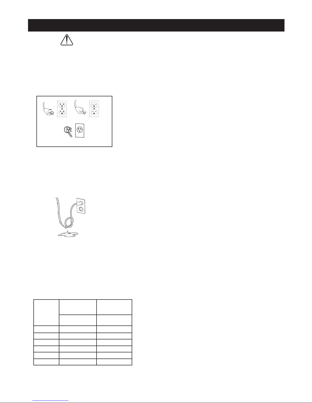
Extension Cord Table
Plugs and Receptacles
IMPORTANT SAFETY INSTRUCTIONS
Safe Electrical Connection
Your Bonding Drill is rated for use on 115VAC
at 50-60Hz. Do not attempt to use drill on
power sources rated other than this.
Typical USA 120v
Wet electrical connections are shock hazards. To
prevent the cutting uid from traveling along the cord
and contacting the plug or power outlet, tie a drip loop
as shown. Also, elevate extension cords or gang
box connections.
WARNING:
Typical USA 230v
230v Type I Plug
Read and understand all instructions. Failure to follow all instructions listed below,
may result in electrical shock, re and/or serious personal injury.
Outdoor Use Extension Cords
When tool is used outdoors, use only extension
cords intended for use outdoors and so marked.
Additional Safety Precautions
Arbor and cutter should never be used as a handhold.
Keep hands and clothing away from all moving parts.
Also, adhere to all operating instructions. Do not drill
through any surface that may contain live electrical
wiring. Drilling into a live wire could cause exposed
metal parts of the drill to be made live. Remove chips
wrapped around cutter and arbor after each hole. With
motor off and power disconnected, grasp chips with
leather gloved hand or pliers and pull while rotating
counterclockwise. Should the cutter become jammed in
the work, stop the unit immediately to prevent personal
injury. Disconnect the drill from the power supply and
loosen jammed cutter by turning the arbor counterclockwise. Never attempt to free the jammed cutter by starting
the motor. Service at authorized repair center only.
Operating Near Welding Equipment
DO NOT operate this unit on the same work surface that
welding is being performed on. Severe damage to the
unit, particularly the power cord, could occur. This could
also result in personal injury to the operator.
Circuit Breaker (If Applicable)
Changing of the circuit breaker to a higher amp rated breaker, or
bypassing the circuit breaker is not recommended and will void
product warranty.
Circuit Breaker Operation (If Applicable)
The circuit breaker is a thermal breaker. When it reaches the
higher temperature rating it will trip and cause the unit to shut
down. This is a protective device and can be rest after 5 to 10
minutes. To reset the breaker, press the breaker button back in.
Extension Cords
Use only 3-wire extension cords that have 3-prong
If it does not reset, let the unit cool a little longer until you can
push the button in and it stays in position.
grounding type plugs and 3-pole receptacles that
accept the tool’s plug. Replace or repair damaged
Save these Instructions.
cords. Make sure the conductor size is large enough
to prevent excessive voltage drop which will cause
loss of power and possible motor damage.
H T G N E L
, D R O C F O
T E E F
5 2 O T P U 6 1 8 1
0 5 - 6 2 4 1 8 1
0 0 1 - 1 5 0 1 6 1
0 0 2 - 1 0 1 8 4 1
0 0 3 - 1 0 2 6 2 1
0 0 5 - 1 0 3 4 0 1
D E D N E M M O C E R
E R I W
E G U A G
R O T O M V 511
S P M A 2 1 - 0 1
D E D N E M M O C E R
E R I W
E G U A G
R O T O M V 0 3 2
S P M A 6 - 5
4
Page 5

INSTALLING / REMOVING BONDING BIT ADAPTER
Installing the Bonding Bit Adapter
Be sure engine is stopped and turned off. Turn off coolant at shut-off.
1. Position the Bonding Bit so the at is in-line with the set screw on the Bonding Bit Adapter. Push the Bonding Bit
into the Bonding Bit Adapter and tighten the set screw.
2. Line the at surface of the Bonding Bit Adapter with the dowel pin that is located at the end of the Arbor Body
Assembly. Push the Bonding Bit Adapter in toward the Arbor Body and twist the Adapter clock-wise until it is locked
into place.
3. Install the correct size rail shoe, according to the size of rail that is being drilled.
The Bonding Bit Adapter is now installed and ready for use. Follow all standard operation procedures to operate your
BD17 Bonding Drill.
Removing the Bonding Bit Adapter
Be sure engine is stopped and turned off. Turn off coolant at shut-off.
1. Position the BD17 so the cutter area is easily access able. While removing the Bonding Bit Adapter, a small amount
of coolant may drain out from the Arbor Body.
2. Push the Bonding Bit Adapter toward the Arbor Body and twist the Adapter counter clock-wise until the Adapter
is unlocked and the at on the Adapter is aligned with the dowel pin in the Arbor Body. Pull the Bonding Bit Adapter
out toward the Clamp Assembly.
3. With the assembly now free from the machine, you now have access to the set screw which holds the Bonding Bit
in place. You can now use a hex key wrench and loosen the set screw to remove the Bonding Bit from the Adapter.
Refer to the installation steps listed above to re-install the Bonding Bit Assembly.
BONDING BIT ADAPTER ASSEMBLY
Twist
OFF
Bonding Bit
Dowel Pin
Twist
ON
Bonding Bit Adapter
Bonding Bit Assembly
(Adapter & Bit)
Bonding Bit 07307 07304 03452 07318
9/32" 8mm 3/8" 13/32"
07305 07302 05565 07316
5
Page 6
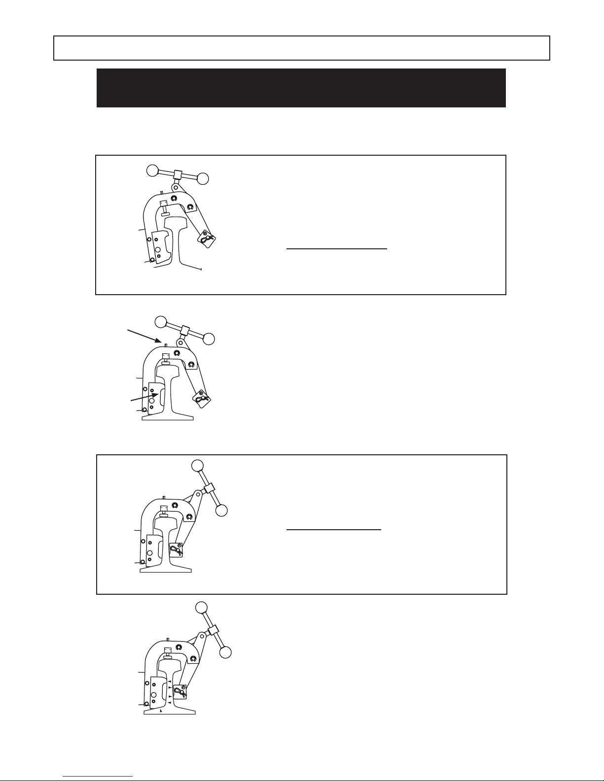
CLAMPING PROCEDURE
-
-
-
WarnInG: Improper ClampInG WIll Cause
premature Cutter FaIlure
Conrm that the correct Rail Shoes have been installed
according to the size of Rail that is being drilled.
step #1:
With clamp in open position, rest unit on
rail base. Bottom of shoes should contact
taper on rail base. (See Fig. A)
* PERFORMACE TIP:
Close clamp until clamp pad contacts
web or rail prior to STEP #2.
FIGURE A.
STEP #3
STEP #2
FIGURE B.
FIGURE C.
step #2:
Raise rear of rail drill to locate shoes in
proper position. (See Fig. B)
step #3:
Loosen locking nut on Height
Adjustment Assembly. Turn Height Screw
to achieve desired hole height. Tighten
locking nut to secure.
step #4:
While maintaining contact between shoes
and rail, tighten clamp. (See Fig. C)
* CLAMPING NOTE:
When you have the clamp tight on the
rail, check for pad contact. If pad contact
is good, tighten clamp handle one more
half turn. DO NOT OVER-TIGHTEN.
FIGURE D.
step #5:
When unit is rmly clamped, check for
proper shoe and pad contact on both
sides again. (See Fig. D)
When properly clamped to the rail there will
be a small gap between the top of the shoe
and the rail.
6
Page 7
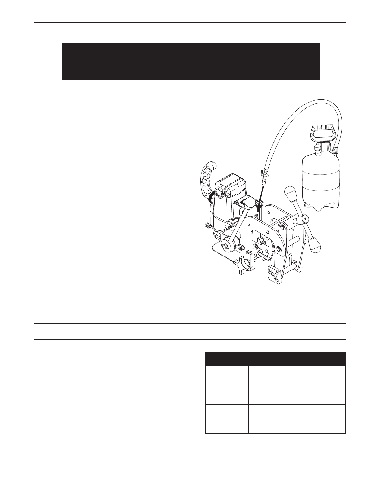
DRILL & PRESSURIZED COOLANT SYSTEM
Do not use straIGHt Water or WInDoW
WasHer FluID. DamaGe to DrIll WIll oCCur!
onlY use traK-star rotamaGIC Coolant.
1. Install correct shoes for rail type being drilled.
2. Install correct size Bonding Bit and Adapter into the
Drill arbor. See Bonding Bit Installation procedure on previous page.
3. Fill coolant bottle with TRAK-STAR cutting uid ( a water
soluble and biodegradable product) Conventional ll
access is achieved by removing pump handle.
Caution: Contents under pressure. Partially open
to slowly release pressure before removing.
4. Attach coolant bottle quick connect hose tting to drill,
located near power button inbetween clamp arms.
5. Pressurize coolant bottle until resistance is felt in the handle.
6. Open coolant shut off valve 1/4” and watch for
coolant ow from the nozzle onto the work surface.
NOTE - Coolant is under pressure -- stay out of path of spray.
If coolant does not ow, rotate valve further to open or unclog
coolant system.
Coolant System Replacement Parts
01569 On/Off Valve
05621 Quick Connect Fitting
01592 Coolant Bottle and Hose Assy
ROTAMAGIC™ CONCENTRATE CUTTING FLUID
A good ow of cutting uid to the tool is important. It cools
and lubricates the cutting edge, helps evacuate the chips,
keeps the slug from expanding, and helps eject the slug.
Various mineral and sulphur base oils are quite popular,
however, water base solutions have better cooling qualities.
Listed is our own recommended Concentrated Cutting Fluid
for Twister Bits and similar cutting tools. It is a water soluble,
biodegradable product. This cutting uid contains no
ingredients that are on the U.S. Government Hazardous
Materials List. It is a super concentrated form that will
require a 10:1 mixture of water.
Part No. Description
(4) 1 Gallon concentrate
11742-4
bottles, makes 11 Gallons
each, or 44 Gallons total.
11743
(1) 5 Gallon concentrate
pail, makes 55 Gallons.
Page 8
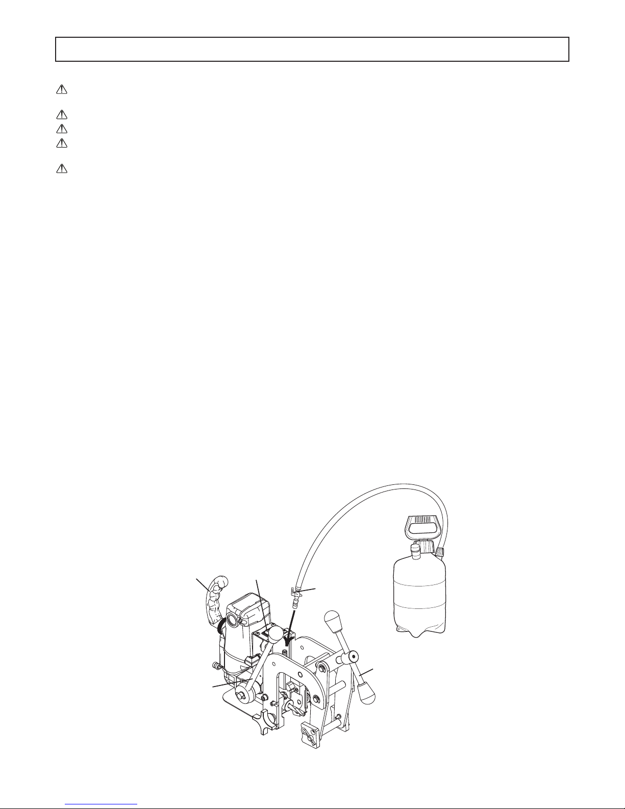
OPERATING INSTRUCTIONS
Important notICe
Read all Safety Instructions listed at the being of this Operators Manual before operating the
BD17 Transducer Drill.
Make sure the cutter is installed properly.
Verify that the correct shoes for the rail that is being drilled is installed.
Always use caution when contacting the rail with the cutting tool. Allow the cutter to enter the rail
before full feed pressure is applied.
Verify that the power cord is clear of any moving objects.
1. Make sure the work piece, cutter and shoes are free of chips or any other forms of debris.
2. Secure the Drill to the rail and adjust height by following the Clamping Procedure listed previously in this Manual.
3. Slowly feed the Bonding Bit to the rail to verify the location of the hole. Once location is veried, retract the Bonding Bit so
it is not contacting the rail.
4. Attach the Pressurized Coolant Bottle by following the procedure listed previously in this Manual. Open the valve on the
Bottle Hose and verify that coolant is owing.
5. Plug the power cord into the correct outlet. If an extension cord is needed, refer to the Extension Cord Chart
in the Safety Instructions for the correct size and length.
6. Make sure the Bonding Bit is free of the work piece and turn the motor ON by moving the rocker switch to the On position.
7. Feed the Arbor slowly until the Bonding Bit makes full contact with the rail. Once full contact is made, full pressure can be
applied to the Feed Handle.
8. Anticipate the end of your cut and ease up on the feed prior to completing the hole.
9. After completing the hole, retract the cutter fully and select OFF on the rocker switch.
10. Close the valve on the Coolant Bottle Hose to stop the coolant ow and unplug the power cord.
11. Loosen the Clamp Assembly and remove the Transducer Drill from the rail.
Carry Handle
Motor
ON/OFF Switch
01569 Coolant
ON/OFF Valve
Feed Handle
Clamp Handle
8
Page 9
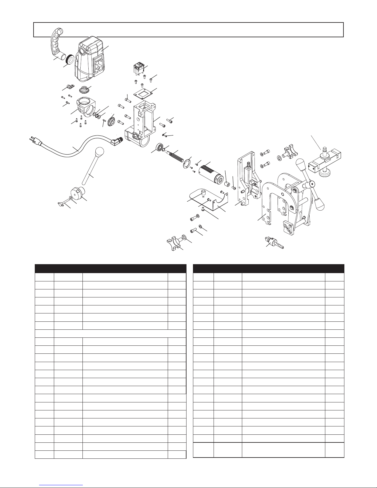
BREAKDOWN & PARTS LIST
1
2
5
6
7
8
9
10
11
12
13
14
15
16
17
18
19
20
23
24
25
26
27
28
29
30
3
4
21
21
22
31
32
33
34
35
36
37
38
39
40
41
42
43
42
*44
For Transducer
Drill Only
Item Part # Description Qty
1 27115 Rail Clamp Assembly 1
2 07189 Housing Assembly 1
3 07241 120V Motor Assembly 1
4 07290 Gear Cap Assembly 1
5 07233 Feed Hub Assembly 1
6 07174 Quill/Arbor Assembly 1
7 07236 120V Power Cord Assembly 1
8 See pg. 5 ( Adapter Install Inst.) for Adapters & Bits
9 07250 Clamp Bracket Assembly 1
10 04918 4-Point Knob 2
11 40110 1/2" Lock Washer 2
12 40558 Screw - SHC 5/16-18 X 3/4 4
13 40107 5/16" Lock Washer 4
14 07190 Feed Handle Assembly 1
15 17291 Screw w/Knob M6-1 X 45mm 1
16 90027 1/4" Flat Washer 1
17 90077 Screw - BHC #10-32 X 1/2 2
18 07186 Rubber Bumper 1
19 90358 Screw - BHC 1/4-20 X 1/2 1
20 07170 Bonding Drill Guard 1
21 17002 Screw - SHC #6-32 X 1/2 7
22 02420 Cable Clamp 1
23 07187 Screw - BHC 1/4-28 X 1/2 1
Item Part # Description Qty
24 07188 Retainer Cup 1
25 17280 Splined Shaft 1
26 17475 Retaining Ring 1
27 04718 Screw - Pan Head #4-40 X 3/8 3
28 17289 Bearing Retaining Washer 1
29 17270 Bearing 32 O.D X 12 I.D X 10mm 1
30 17277 1/8 Sq Key X .53 1
31 17278 Right Hand Miter Gear 1
32 17502 Left Hand Miter Gear 1
33 10553 Screw - SHC 1/4-20 X 7/8 4
34 07237 120V Rocker Switch 1
35 07245 Screw - BHC M5 X 12 mm 4
36 07168 Switch Plate 1
37 05920 Locking Nut 3/4-14 NPT 1
38 05921 Carring Handle 1
39 75096 Screw - SHC M6-1 X 20mm 2
40 90052 Lock Washer 1
41 24082 Screw - SHC #6-32 X 3/8 1
42 17517 Thrust Washer .312 X .750 2
43 17516 Thrust Bearing 1
*44 07556
05372 Lubiplate Grease
Height Adjustment Bracket
(For Transducer Drill Only)
9
1
Page 10
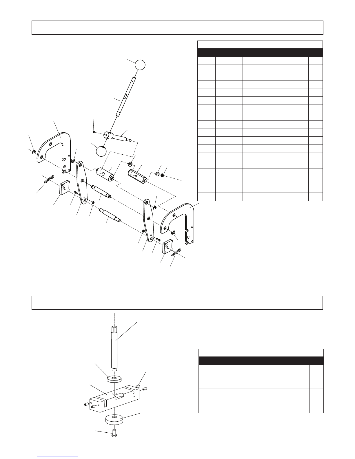
CLAMP ASSEMBLY
27080 CLAMP HANDLE ASSEMBLY
10
*
12
*
item 19 inludes these parts.
*
2
1
3
4
5
11
*
13
*
10
*
1
15
*
14
8
6
7
9
16
17
18
*
*
1
Item Part # Description Qty
1 27066
2 27110 Primary Clamp Arm 2
3 03501 Hitch Pin 2
4 27062 Clamp Pad 2
5 90098 Screw - #10-24 X 3/4 2
6 27022 Secondary Clamp Arm 2
7 10662 Lock Nut #10-24 2
8 27024 Pin 1
9 27023 Pin 1
10 04532
11 02470
12 03522 Clamp Turn Handle 1
13 27027 Clamp Feed Screw 1
14 27026 Bushing 1
15 04782 Flat Washer 1
16 27025 Bushing 1
17 40074 5/16 Flat Washer 1
18 03563 5/16-18 Hex Nut 1
2
Retaining Ring Set
Knob
Set Screw 1/4-28 X 3/8
1
2
1
7
6
5
4
1
3
HEIGHT ADJUSTMENT (For Transducer Drill Only)
1
07556 HEIGHT ADJUSTMENT ASSEMBLY
2
4
3
5
Item Part # Description Qty
1 07554
2 51043 Lock Nut 1
3 07553 Height Mount Bracket 1
4 05473 Screw - #10-32 X 3/8 4
5 07555 Rail Pad 1
6 27022 Screw - 1/4-20 X 1/2 1
Height Adjustment Screw
1
6
10
Page 11
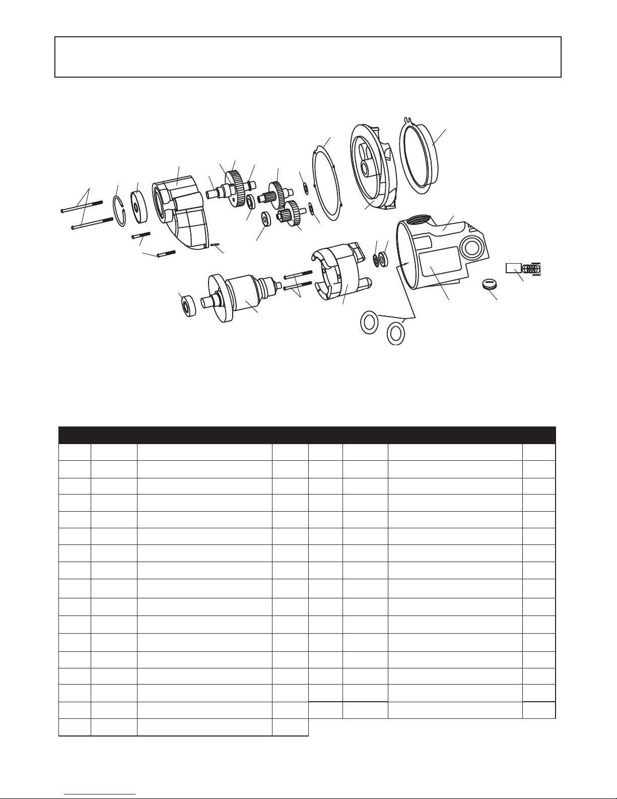
MOTOR BREAKDOWN & PARTS LIST
07241 - 120V Motor Assembly 07291 - 230V Motor Assembly
26
25
24
27
10
23
22
21
28
20
18
19
5
11
4
17
14
16
15
13
12
6
5
1
8
9
7
29
30 opposite side
2
3
Item Part # Description Qty Item Part # Description Qty
1 17621 Carbon Brush 2 16 17607 1st Inter. Gear Assy 1
2 17622 Brush Cap 2 17 17608 2nd Inter. Gear Assy 1
3 17632 Paper Washer 2 18 17603 Ball Bearing 1
4 17600 Field Case 1 19 17626 Retaining Ring 1
5 17602 Ball Bearing 2 20 17609 Spur Gear 1
6 17606 Dust Seal 1 21 17611 Key 1
7 17628 120V Field 1 22 17616 Spindle 1
17629 230V Field 1 23 17615 Gear Housing
8 17623 Pan Head Screw 2 24 17605 Ball Bearing 1
9 17630 120V Armature 1 25 17627 Retaining Ring 1
17631 230V Armature 1 26 17625 Pan Head Screw Long 2
10 17604 Ball Bearing 1 27 17624 Pan Head Screw Short 2
11 17617 Fan Guide 1 28 17612 Dowel Pin 1
12 17601 Gear Housing 1 29 07243 Label - Motor Safety 1
13 17618 Gasket 1 30 07242 Label - Motor Specs 120V 1
14 17613 Flat Washer 1 07292 Label - Motor Specs 230V 1
15 17610 Flat Washer 1
(includes 24 & 25) 1
11
Page 12
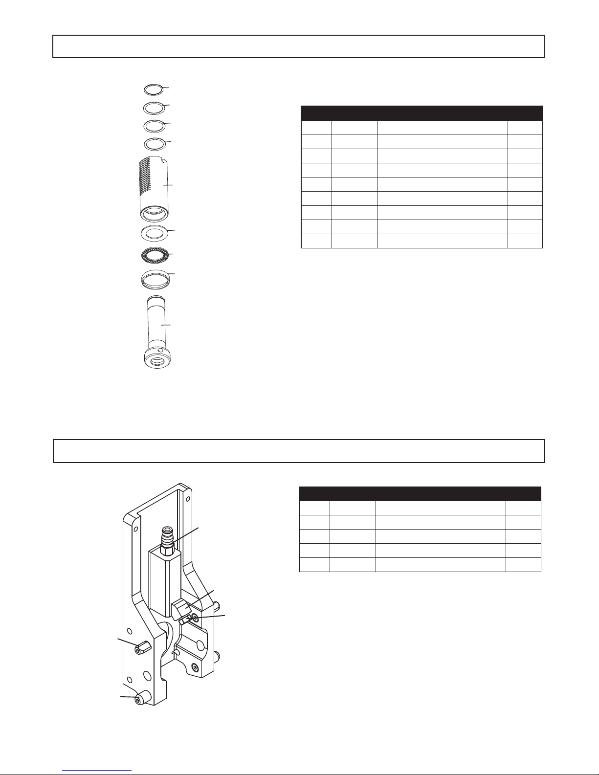
1
2
3
4
5
6
7
8
6
*
*
*
Apply a light coat of grease to
these parts if 07174 is disassembled.
07174 ARBOR/QUILL BREAKDOWN & PARTS LIST
Item Part # Description Qty
1 07173 Arbor Assembly 1
2 17643 Thrust Bearing Shield 1
3 17645 Thrust Bearing 1
4 17644 Bronze Thrust Washer 1
5 07172 Quill Assembly 1
6 17547 Steel Thrust Washer 2
7 17546 Bronze Thrust Washer 1
8 04720 Spiral Retaining Ring 1
9 24152 GR132 Lubiplate Grease
07250 Clamp Bracket Assy. Breakdown & Parts List
3
4
1
5
2
Item Part # Description Qty
1 27006 Locating Pin - Diamond Shape 2
2 27007 Locating Pin - Round 2
3 05646 Quick Connect Fitting - male 1
o
4 07251 45
5 07185 Spray Nozzle 1
Fitting 1
12
Page 13
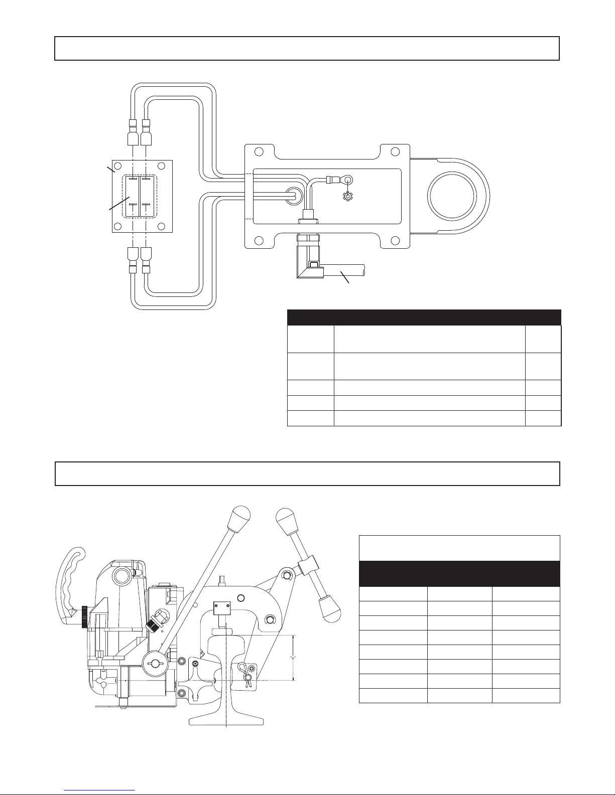
SWITCH PLATE
ROCKER SWITCH
CONTROL PANEL & WIRING BREAKDOWN
POWER WIRE-BLACK
POWER WIRE - WHITE
GREEN
GROUND WIRE
MOTOR WIRE WHITE
MOTOR WIRE - BLACK
Part # Description Qty
POWER CORD ASSEMBLY
07236 120V Power Cord Assembly
(includes Power cord & Strain Relief)
07295 230V Power Cord Assy. Type I Plug
(includes Power cord & Strain Relief)
07237 120V Rocker Switch 1
07293 230V Rocker Switch 1
07168 Switch Plate 1
HEIGHT SIZING FOR TRANSDUCER DRILLING
All Dimension Taken fom Top (Head) of Rail
to Centerline of Bonding Bit
Rail Sizes A DIM.
Minimum
112 AREA 3.12 3.19
115 AREA 3.34 3.54
119 AREA 3.50 3.62
129 AREA 3.73 3.98
130 AREA 3.38 3.53
131 AREA 3.16 3.31
132 AREA 3.38 3.50
136 AREA 3.50 3.80
1
1
A DIM.
Maximum
13
Page 14
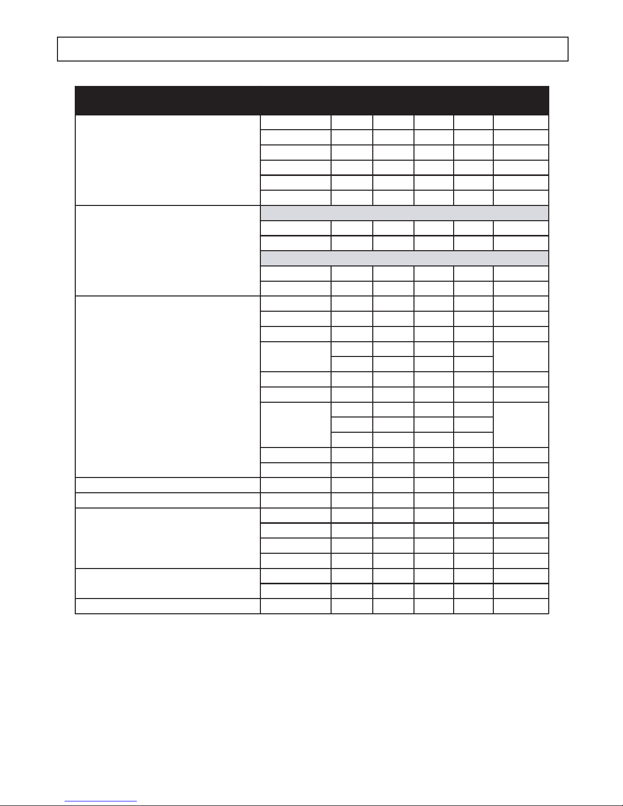
RAIL & SHOE DATA
Railway Association or System
ASCE - American Society
of Civil Engineers
ARA - American
Railway Association
AREA - American Railway
Engineering Association
CSX122 --- 122CB --- 01918
UP (former C & NW)100 10035 100DM10035 01926
PS - Pennsylvania System
NYC (Dudley) - New Yo rk Central &
Hudson River Railroad
PRR - Pennsylvania Railroad 85 853385PR --- 01917
Tee Rail
Section (lb.)
70 704070AS701 01906
75 754075AS 753 01907
80 804080AS 800 01908
85 854085AS851 01909
90 904090AS --- 01910
10010040 100AS --- 01911
Type "A" - High Rail for High Speeds
90 902090RA 902 01927
10010020 100RA100301928
Type "B" - Lower Rail for Heavy Loads @ Slower Speeds
90 903090RB 905 01908
10010030 100RB100201910
10010025 100RE10025 01894
11011025 110RE110001895
11211228 112RE112101896
115/119
13013025 130RE130001898
13113128 131RE131101899
132/136/141
13313331 133RE133001901
140 --- 140RE --- 01903
85 8531 85 PS --- 01912
10010031 100PS --- 01913
13013031 130PS --- 01914
15515531 155PS --- 01919
10510524 105DY --- 01915
12712723 127DY --- 01916
Section Designation
11525 115RE1150
11937 119RE1190
13228 132RE1321
--- 141 --- ---
Shoe
Part No.
01897
0190213622 136RE13637
14
Page 15
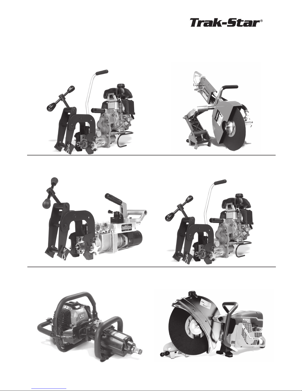
Modern, high speed railways and welded rails call for modern, high precision rail equipment.
Through our continual commitment, we now offer additional products that will be beneficial to
your specific applications.
OTHER PRODUCTS OFFERED BY TRAK-STAR
Model RB28
Portable Gas Rail Drill
Model RM42
Power Feed Hydraulic Drill
Model HS16
Hydraulic Rail Saw
Model RB30
Portable Gas Bonding Drill
Model GW12
Gas Impact Wrench
Model K1270
Portable Gas Rail Saw
15
Page 16
Commercial / Industrial Limited Warranty
Hougen Manufacturing, Incorporated warrants its Trak-Star Rail Drills, Portable Magnetic Drills,
Electro-hydraulic Hole Punchers for one (1) year and other products for ninety (90) days from date of
purchase against defects due to faulty material or workmanship and will repair or replace (at its option) without
charge on any items returned. This warranty is void if the item has been damaged by accident or unreasonable use, neglect, improper service, or other causes not arising out of defects in material or workmanship. No
other expressed warranty is given or authorized. Hougen Manufacturing, Inc., disclaims any implied warranty
of MERCHANTABILITY or FITNESS for any period beyond the expressed warranty and shall not be liable
for incidental or consequential damages. Some states do not allow exclusions of incidental or consequential
damages or limitation on how long an implied warranty lasts and, if the law of such a state governs your
purchase, the above exclusion and limitation may not apply to you. This warranty gives you specic legal
rights and you may also have other rights which vary from state to state.
To obtain warranty service, return the item(s), transportation prepaid, to your nearest Factory Authorized
Repair Center or to Hougen Manufacturing, Inc. 3001 Hougen Drive, Swartz Creek, Michigan 48473.
THIS WARRANTY IS IN LIEU OF ANY OTHER WARRANTY, EXPRESSED OR IMPLIED, INCLUDING ANY
WARRANTY OF MERCHANTABILITY OR FITNESS FOR A PARTICULAR PURPOSE.
© 2018 Hougen Manufacturing, Inc.
FACTORY AUTHORIZED WARRANTY REPAIR CENTERS
Hougen Manufacturing, Inc. Kenbil Service Co.
3001 Hougen Drive 2900 Adams Street B-14
Swartz Creek, MI 48473 Riverside, CA 92504
(866) 245-3745 (951) 689-6633
Photographs and Specications shown are accurate in detail at time of printing. Manufacture reserves the
right to make improvements and modications without prior notice.
Hougen, Hougen-Edge, Trak-Star, and Punch-Pro are propriety trademarks of Hougen
Manufacturing, Inc. Ogura and the Ogura logo are proprietary trademarks of Ogura & Co., Ltd. Honda logo
appears courtesy of American Honda Motor Co.
Hougen Manufacturing, Inc.
P.O. Box 2005 • Flint, MI 48501-2005
3001 Hougen Drive • Swartz Creek, MI 48473
Hougen Manufacturing has received the
Association of American Railroads
Quality Assurance Program Certication
Phone: (866) 245-3745 • Fax (800) 309-3299
E-Mail: [email protected]
On-line: www.trak-star.com
OMBD171215 Printed in U.S.A.
© 2018 Hougen Manufacturing, Inc.
 Loading...