

Page 1

Thank you for making TrakPower your
choice in brushless power systems.
™
BRUSHLESS MOTOR
TrakPower brushless motors are built
with the fi nest raw materials available
to provide the best and most effi cient
power possible. CNC machined aluminum
ribbed cans and cooling vents provide
excellent heat dissipation, keeping the
operating temperatures low for better
performance and longevity. The high
temperature resistant rotor is coated
to prevent breakdown of the magnet
strength. The TrakPower MS series
motors are a perfect match for the
TrakPower MS-1 Brushless Racing ESC.
Specifi cations
PART NUMBER
TURN
INPUT VOLTAGE 2–3S LiPo
MOUNT HOLE DEPTH 4mm
SHAFT DIAMETER 3.175mm
SHAFT LENGTH 15mm
DIMENSIONS 35.9 x 52.4mm
WEIGHT 175g167g
TKPC5015
6.5T 8.5T 10.5T
TKPC5025 TKPC5035 TKPC5040 TKPC5045 TKPC5050
13.5T 17.5T 21.5T
Warnings
Please read thoroughly before installation and operation.
DO NOT apply an input voltage that exceeds
•
the maximum specifi cations of each motor.
DO NOT allow the input connectors to touch
•
each other while power is applied to the
motor. Make sure all input connections are
insulated electrically.
DO NOT attempt to modify this motor.
•
DO NOT allow water or moisture to enter the
•
motor, as it can cause permanent damage
to the motor and possibly short out the
attached ESC.
Allow the motor to cool down after each run.
•
DO NOT attempt to use a damaged motor
•
(having mechanical or electrical defects).
Page 2
Installation
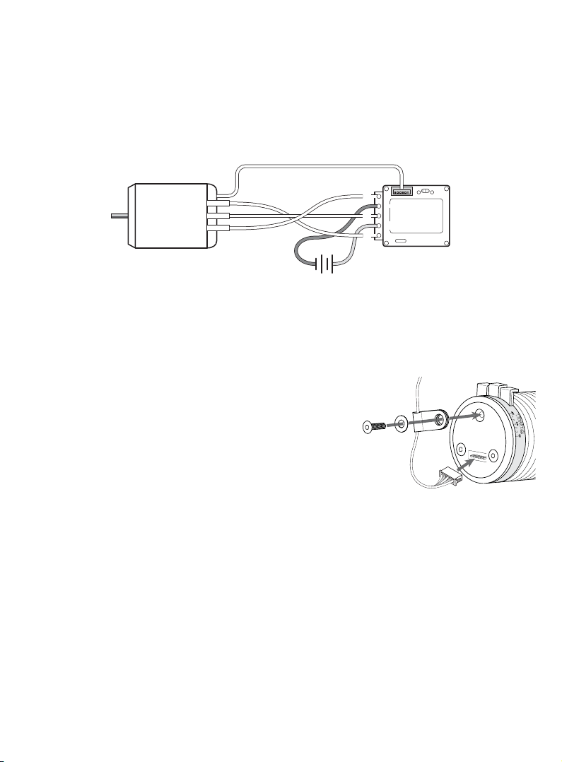
Please reference the diagram below for the correct wiring confi guration. The solder posts
located on the ESC should be labeled “A”, “B” and “C”. These posts will correspond to the “A”,
“B” and “C” tabs on the motor. “A” wire goes to “A” tab on the motor, “B” goes to “B” and “C”
goes to “C”. Pay special attention when soldering the ESC wires to the motor tabs not to allow
the tabs and/or wires to become soldered together.
Sensor
BRUSHLESS
MOTOR
C
B
A
k
c
Battery
a
l
B
A
–
B
+–+
C
d
e
+−
R
After the main motor power wires are installed, the included sensor wire can be connected.
This sensor wire will connect between the ESC and motor. Connect one end of the sensor wire
to the motor and the other end to the ESC. Be sure that the connections are tight.
Once the above steps are completed, it is recommended to install the included sensor clip.
A longer screw is included for the installation of the sensor clip. This sensor clip secures the
sensor wire and prevents it from disconnecting during use.
1. Remove one screw from rear of motor.
2. Insert sensor wire into clip.
3. Use included screw and washer to secure clip to rear of motor.
Note: Do not pinch the sensor wire during installation. This could
cause intermittent operation or performance issues.
Mechanical Timing
This motor is equipped with adjustable timing. The timing is advanced 30° from the factory.
Timing can be advanced or retarded by loosening the three end bell screws by one full turn.
Rotate clockwise to retard the timing (more bottom end, less top end) or rotate counterclockwise to advance the timing (less bottom end, more top end). Re-tighten the screws and
be careful not to over tighten.
It is recommended to only adjust timing in 5° increments (one mark) at a time. Motor gearing
may also change due to the advancement or retardation of motor timing. It is recommended
to run in 1 minute increments to carefully monitor motor and ESC temperatures. The motor
temperature should NEVER exceed 180°F (83°C). TrakPower offers a reliable temperature
gauge to monitor motor and ESC temperatures. This temperature gauge also includes a stop
watch to monitor run times (TKPP9000, TrakPower Infrared Temperature Gauge w/ Stopwatch).
Page 3

General Maintenance
General maintenance is recommended for brushless motors to ensure they are operating
effi ciently and to prolong the life of the motor. Prior to maintenance, the motor should be
removed from the vehicle. This includes de-soldering the three main power wires (A, B and C),
disconnecting the sensor wire and removing the pinion gear.
Inspect the outside of the motor for damages including the motor shaft, can, sensor port and
motor tabs. Also inspect power and sensor wires for damage. Use a cloth to wipe off any debris
from the motor. Compressed air can be used to lightly blast the motor to remove any stubborn
dirt/dust from hard to reach areas. A good shot of air is usually enough to clean out the inside
of the motor without disassembly. Be careful not to blast the bearings with air. This could force
dirt and debris into the bearing causing premature failure, unwanted friction and heat build-up.
IMPORTANT: Disassembly of motor will void warranty.
To further inspect for damages or to replace parts the motor must be disassembled. Start by
using a 2.0mm hex driver to remove the three screws located on the motor’s front plate. Once
the screws are removed, the front plate and end bell can be removed. Note: The sensor board
and timing ring will remain attached to the end bell until the three screws securing it are
removed. It is not necessary to remove these three screws unless replacing the sensor board
or adjusting the timing. To remove the rotor, use a pair of pliers to grip the shaft and pull out.
Below is an exploded view for reference.
Inspect all surfaces for damage. Spin bearings to make sure they rotate freely. Use compressed
air to remove any dust and debris from inside the motor. If compressed air is not enough to
remove the debris, use electronic motor spray or contact cleaner and spray the inside of the
motor until the runoff is clear. Allow the motor to completely dry out before re-assembly.
Upon re-assembly, be sure that the motor can screws are snug. DO NOT overtighten. Once
general maintenance is completed, use a drop of light bearing oil on the front and rear bearing
of the motor. Follow the installation steps at the beginning of this manual to re-install the motor.
Page 4

Replacement Items
TrakPower offers a full line of replacement items for brushless motors. Below is a list of
TrakPower replacement parts currently available:
TKPC7210 MS Brushless Motor Bearings (2)
TKPC7230 MS BL Motor Sensor Board
TKPC7240 MS BL Motor Rotor 12.5mm
TKPC7255 Woven Sensor Wire 175mm
TKPC7260 Sensor Clip/Washer/Screw
TKPC7270 MS BL Motor Timing Ring
TKPC7106 6.5T BL Motor Front/End Bell
TKPC7108 8.5T BL Motor Front/End Bell
TKPC7110 10.5T BL Motor Front/End Bell
TKPC7113 13.5T BL Motor Front/End Bell
TKPC7117 17.5T BL Motor Front/End Bell
TKPC7121 21.5T BL Motor Front/End Bell
Warranty
TrakPower warrants this product to be free from defects in materials and workmanship for a
period of 120 days from the date of purchase. During that period, we will repair or replace, at
our option, any product that does not meet these standards. You will be required to provide
proof of purchase date (receipt or invoice). If, during the warranty period, your motor shows
defects caused by abuse, misuse or accident, it will be repaired or replaced at our option, at
a service charge not greater than 50% of the current retail list price. Be sure to include your
daytime telephone number in case we need to contact you about your repair. This warranty
does not cover components worn by use, application or reverse voltage, cross connections,
poor installation, subjection of components to foreign materials, or tampering. In no case shall
our liability exceed the original cost of the product. Your warranty is voided if:
You apply an input voltage that exceeds the maximum specifi cations of the motor.
•
You allow water or moisture to enter the motor.
•
You disassemble, attempt to modify or tamper with this motor.
•
Under no circumstances will the purchaser be entitled to consequential or incidental damages.
This warranty gives you specifi c legal rights, and you have other rights which vary from state
to state.
For service to your TrakPower motor, either in or out of warranty, send it post-paid and insured to:
Hobby Services
3002 N. Apollo Dr. Suite 1
Champaign, IL 61822
(217) 398-0007
Email: hobbyservices@hobbico.com
trakpowerusa.com
TKPC5015/5025/5035/5040/5045/5050 v1.1
© 2013 Hobbico, Inc. All rights reserved.
 Loading...