

Trak Machine Tools ProtoTRAK SMX K2, ProtoTRAK SMX Retrofit, ProtoTRAK SMX K3, ProtoTRAK SMX K4 Safety, Installation, Maintenance, Service And Parts List

Document: P/N 24319
Version: 082718
2615 Homestead Place
Rancho Dominguez, CA 90220-5610 USA
T | 310.608.4422 | F | 310.764.2668
Service Department: 800.367.3165
e-mail: sales@trakmt.com | service@trakmt.com | web:
www.trakmt.com
ProtoTRAK® SMX
K2, K3, K4 & Retrofit
Safety, Installation, Maintenance, Service & Parts List Manual

Copyright 2018, Southwestern Industries, Inc. All rights are reserved. No part of this publication may be reproduced,
stored in a retrieval system, or transmitted, in any form or by any means, mechanical, photocopying, recording or
otherwise, without the prior written permission of Southwestern Industries, Inc.
While every effort has been made to include all the information required for the purposes of this guide, Southwestern
Industries, Inc. assumes no responsibility for inaccuracies or omission and accepts no liability for damages resulting from
the use of the information contained in this guide.
All brand names and products are trademarks or registered trademarks of their respective holders.

Table of Contents
1.0 Safety ................................................................................................................................................................ 1
1.1 Safety Publications .......................................................................................................................................... 1
1.2 Danger, Warning, Caution, and Note Labels & Notices As Used In This Manual ................................................... 1
1.3 Safety Precautions .......................................................................................................................................... 4
2.0 Installation ....................................................................................................................................................... 6
2.1 Floor Plan, Layout & Space Requirements – K2, K3 & K4 ................................................................................... 6
2.2 Uncrating ....................................................................................................................................................... 8
2.3 Shortages: Inventory Checklist ....................................................................................................................... 8
2.4 Installation Instructions & Checklist .................................................................................................................. 9
2.5 Machine Specifications .................................................................................................................................. 10
2.6 Maximum Work Capacities ............................................................................................................................. 10
2.7 ProtoTRAK SMX Control Hardware .................................................................................................................. 11
2.8 Lifting and/or Moving the Machine ................................................................................................................. 14
2.9 Cleaning ....................................................................................................................................................... 16
2.10 Leveling: Leveling Tolerance is .0005”/10” ................................................................................................... 16
2.11 Electrical Connection ................................................................................................................................... 18
2.11.1 Phase Converters .................................................................................................................................. 21
2.11.2 Flange Disconnect/Transformer (Optional) .............................................................................................. 21
2.12 Air Connection - Optional ............................................................................................................................. 25
2.13 Mounting the Display Pendant ..................................................................................................................... 26
2.14 Cable Interconnections ............................................................................................................................... 26
2.15 Lubrication ................................................................................................................................................. 33
2.15.1 Manual Lubrication ............................................................................................................................... 33
2.15.2 Head Lubrication .................................................................................................................................. 35
2.16 ProtoTRAK SMX Euclid Block Procedure ........................................................................................................ 36
3.0 Troubleshooting by Symptom ........................................................................................................................... 38
3.1 Problems Relating to Machining Results ......................................................................................................... 38
3.1.1 Poor Finish.............................................................................................................................................. 38
3.1.2 Circles Out of Round ............................................................................................................................... 38
3.1.3 Taper Cut on a Programmed Straight Line Move ....................................................................................... 39
3.1.4 Parts Have Incorrect Dimensions .............................................................................................................. 40
3.2 Problems Regarding the Motion of the Machine ............................................................................................... 41
3.2.1 Run Away Axis ....................................................................................................................................... 41
3.2.2 Slow Down Axis ..................................................................................................................................... 41
3.2.3 Axis Will Not Jog ..................................................................................................................................... 42
i
TRAK Machine Tools
Southwestern Industries, Inc.
ProtoTRAK SMX K2, K3, K4 & Retrofit Safety, Installation, Maintenance, Service & Parts List Manual

3.2.4 Axis Motor Motion Is Not Smooth ............................................................................................................. 42
3.2.5 Vibration in Motion .................................................................................................................................. 43
3.2.6 Searching Axis ........................................................................................................................................ 43
3.3 Problems Relating to the Operation of the Control .......................................................................................... 44
3.3.1 Display Blanks ........................................................................................................................................ 44
3.3.2 Bad Picture on the Display ...................................................................................................................... 44
3.3.3 Keyboard Lockup ................................................................................................................................... 44
3.3.4 Fault X or Y ........................................................................................................................................... 44
3.3.5 Problems Reading the Floppy Disk; Programs Not Saved Properly .............................................................. 45
3.3.6 System Will Not Turn On or Boot-Up ........................................................................................................ 45
3.3.7 System Reboots by Itself ......................................................................................................................... 46
3.3.8 System Shuts Off .................................................................................................................................... 46
3.3.9 Will Not Hold Calibration ......................................................................................................................... 46
3.3.10 Auxiliary Functions Not Working (Option on 3 Axis Machines Only) .......................................................... 47
3.3.11 E-Stop Error ......................................................................................................................................... 47
3.3.12 Limit Switch Error - Optional .................................................................................................................. 48
3.4 Problem with the Measurements .................................................................................................................... 48
3.4.1 X, Y and Z-Axis Measurements Do Not Repeat .......................................................................................... 48
3.4.2 X, Y, and Z-Axis Measurements Are Not Accurate ...................................................................................... 50
3.4.3 The DRO Is Not Counting ....................................................................................................................... 50
3.4.4 X, Y, and Z-Axis DRO Counting in Wrong Direction .................................................................................... 50
3.4.5 X, Y, & Z-Axis Electric Handwheels Count in Wrong Direction ..................................................................... 50
3.5 Problems with the Machine Tool .................................................................................................................... 51
3.5.1 Spindle Stalls or Turns-Off During Machining ........................................................................................... 51
3.5.2 Spindle Motor Hums or Will Not Run ........................................................................................................ 51
3.5.3 Spindle Runs Backwards ......................................................................................................................... 53
3.5.4 Head Noise ............................................................................................................................................. 53
4.0 Diagnostics ..................................................................................................................................................... 55
4.1 The Machine Tool & Set-Up .......................................................................................................................... 55
4.1.1 The Milling Machine Checklist .................................................................................................................. 55
4.1.2 A Special Word About X & Y Gibs ............................................................................................................ 55
4.1.3 Lubrication............................................................................................................................................. 56
4.1.4 Machining Set-Up ................................................................................................................................... 56
4.2 The Mechanical Drive Train (X, Y) ................................................................................................................. 57
4.2.1 Keys to Ball Screw Alignment ................................................................................................................ 58
4.3 Computer/Pendant Diagnostics ...................................................................................................................... 58
4.4 Motor Diagnostics ......................................................................................................................................... 59
4.4.1 Cable Connections ................................................................................................................................... 60
ii
TRAK Machine Tools
Southwestern Industries, Inc.
ProtoTRAK SMX K2, K3, K4 & Retrofit Safety, Installation, Maintenance, Service & Parts List Manual

4.4.2 To Check the Motor Encoders .................................................................................................................. 60
4.4.3 Encoder Counts to Pendant ...................................................................................................................... 60
4.4.4 Moving Problem from One Axis to Another ................................................................................................ 60
4.5 Servo Driver ................................................................................................................................................. 60
4.6 Glass Scales .................................................................................................................................................. 61
4.6.1 Alignment of scales ................................................................................................................................. 61
4.6.2 Measurements Do Not Repeat .................................................................................................................. 61
4.7 TRAK Sensors ............................................................................................................................................... 62
4.7.1 Faulting Axis .......................................................................................................................................... 62
4.7.2 Measurements Do Not Repeat .................................................................................................................. 62
4.8 Electrical ...................................................................................................................................................... 63
4.8.1 Checking A/C Voltage .............................................................................................................................. 63
4.8.2 Checking Fuses ....................................................................................................................................... 63
4.8.3 Cable Breakout Box Connections .............................................................................................................. 64
4.8.4 Cable Connections .................................................................................................................................. 64
4.9 Service Codes ............................................................................................................................................... 68
4.9.1 Software Codes ...................................................................................................................................... 69
4.9.2 Machine Set-up Codes ............................................................................................................................. 70
4.9.3 Diagnostic Codes. ................................................................................................................................... 72
4.9.4 Operator Defaults/Options Codes ............................................................................................................. 73
5.0 Procedures for Replacements & Maintenance ..................................................................................................... 74
5.1 Replacements .............................................................................................................................................. 74
5.1.1 Servo Motor Replacement ........................................................................................................................ 74
5.1.2 Servo Driver Replacement........................................................................................................................ 74
5.1.3 Computer Module and LCD/Enclosure Replacement ................................................................................... 75
5.1.4 System Flash Disk Replacement ............................................................................................................... 77
5.1.5 Cable Routing on Machine ....................................................................................................................... 79
5.1.6 TRAK Sensor .......................................................................................................................................... 79
5.1.7 Glass Scale Replacement ......................................................................................................................... 82
5.1.8 Power Drawbar ....................................................................................................................................... 86
5.1.9 Ball Screw Replacement, X-Axis (Table) ................................................................................................... 88
5.1.10 Ball Screw Replacement, Y-Axis (Saddle) ................................................................................................ 91
5.1.11 Air Solenoid Replacement – Auxiliary Function Machines Only .................................................................. 94
5.1.12 Spindle Motor Wiring ............................................................................................................................. 94
5.1.13 Feed Trip Adjustment (not applicable to 3 axis controls) .......................................................................... 95
5.1.14 Quill Clock Spring Replacement and Adjustment ...................................................................................... 95
5.1.15 Spindle Motor Removal and Replacement ............................................................................................... 96
5.1.16 Drive Belt Replacement ......................................................................................................................... 97
iii
TRAK Machine Tools
Southwestern Industries, Inc.
ProtoTRAK SMX K2, K3, K4 & Retrofit Safety, Installation, Maintenance, Service & Parts List Manual

5.1.17 Timing Belt Replacement ....................................................................................................................... 98
5.1.18 Brake Shoe Replacement ....................................................................................................................... 98
5.1.19 Spindle Replacement ............................................................................................................................. 99
5.2 Maintenance ............................................................................................................................................... 100
5.2.1 Gib Adjustments ................................................................................................................................... 100
5.2.2 Calibration & Backlash Constants ........................................................................................................... 103
5.2.3 Head Rotational and Tramming .............................................................................................................. 105
5.2.4 Limit Switch Option ............................................................................................................................... 107
6.0 Retrofit Installation ......................................................................................................................................... 109
6.1 Installation Tools and Hardware ................................................................................................................... 109
6.2 Required Tools/Hardware ........................................................................................................................... 109
6.3 Suggested Fastener Stock ............................................................................................................................ 110
7.0 Installation Procedures ................................................................................................................................... 111
7.1 X and Y Ball Screw Installation ..................................................................................................................... 111
7.1.1 Removing the Table and Leadscrews ...................................................................................................... 111
7.1.2 X-Axis Ball Screw Installation - Part 1 .................................................................................................... 113
7.1.3 Y-Axis Ball Screw Installation ................................................................................................................ 115
7.1.4 X-Axis Ball Screw Installation - Part 2 ..................................................................................................... 120
7.2 Motor/Servo Driver Installation .................................................................................................................... 124
7.2.1 X-Axis Motor/Servo Driver Installation .................................................................................................. 124
7.2.2 Y-Axis Motor and Servo Driver Installation .............................................................................................. 125
7.3 Pendant Installation ..................................................................................................................................... 126
7.3.1 Pendant Arm Installation ....................................................................................................................... 126
7.3.2 Installation of the Pendant Display ......................................................................................................... 127
7.4 Cable Breakout Box Mounting ...................................................................................................................... 128
7.5 Z-Axis Glass Scale Installation ...................................................................................................................... 128
7.6 TRAK Sensor Installation - Optional .............................................................................................................. 130
7.6.1 X and Y Axis Sensor .............................................................................................................................. 130
7.7 X and Y Glass Scale Installation - Optional .................................................................................................... 133
7.7.1 X Axis Scale Installation ......................................................................................................................... 133
7.7.2 Y Axis Scale Installation ......................................................................................................................... 134
7.8 Limit Switch Installation .............................................................................................................................. 136
7.9 System Interconnection ............................................................................................................................... 138
7.9.1 ProtoTRAK SMX Basic System Configuration ............................................................................................ 138
7.9.2 Cable Routing ....................................................................................................................................... 138
8.0 Z Motor/Ball Screw Assembly .......................................................................................................................... 139
8.1 Installation of the Base Plate ....................................................................................................................... 139
8.2 Installation of the Ball Screw ....................................................................................................................... 142
iv
TRAK Machine Tools
Southwestern Industries, Inc.
ProtoTRAK SMX K2, K3, K4 & Retrofit Safety, Installation, Maintenance, Service & Parts List Manual

8.3 Installation of the Motor and Remaining Components .................................................................................... 142
8.4 Lagun Z Axis Cutout .................................................................................................................................... 148
9.0 Introduction to Self-Service ............................................................................................................................. 149
9.1 When You Have a Service Problem ............................................................................................................... 149
9.1.1 Communication with the SWI Customer Service Group ............................................................................ 149
9.2 Replacements .......................................................................................................................................... 150
9.2.1 Exchange Program ................................................................................................................................ 150
10.0 Figures and Parts Lists .................................................................................................................................. 151
TRAK Warranty Policy ............................................................................................................................................ 211
v
TRAK Machine Tools
Southwestern Industries, Inc.
ProtoTRAK SMX K2, K3, K4 & Retrofit Safety, Installation, Maintenance, Service & Parts List Manual

1.0 Safety
The safe operation of the TRAK K Mills depends on its proper use and the precautions taken by each operator.
Read and study this manual and the ProtoTRAK SMX Programming, Operating, and Care Manual. Be certain every
operator understands the operation and safety requirements of this machine before its use.
Always wear safety glasses and safety shoes.
Always stop the spindle and check to ensure the CNC control is in the stop mode before changing or adjusting the tool or
workpiece.
Never wear gloves, rings, watches, long sleeves, neckties, jewelry, or other loose items when operating or around the
machine.
Use adequate point of operation safeguarding. It is the responsibility of the employer to provide and ensure point of
operation safeguarding per OSHA 1910.212 - Milling Machine.
1.1 Safety Publications
Refer to and study the following publications for assistance in enhancing the safe use of this machine.
Safety Requirements for Manual Milling, Drilling and Boring Machines with or without Automatic Control
(ANSI B11.8-2001). Available from The American National Standards Institute, 1819 L Street N.W., Washington D.C.
20036
Concepts And Techniques Of Machine Safeguarding (OSHA Publication Number 3067). Available from The
Publication Office - O.S.H.A., U.S. Department of Labor, 200 Constitution Avenue, NW, Washington, DC 0210.
1.2 Danger, Warning, Caution, and Note Labels & Notices As Used In This
Manual
DANGER - Immediate hazards that will result in severe personal injury or death. Danger labels on the machine are red
in color.
WARNING - Hazards or unsafe practices which
Warning labels on the machine are orange in color.
CAUTION - Hazards or unsafe practices, which
Caution labels on the machine are yellow in color.
NOTE - Call attention to specific issues requiring special attention or understanding.
could
result in severe personal injury and/or damage to the equipment.
could
result in minor personal injury or equipment/product damage.
1
TRAK Machine Tools
Southwestern Industries, Inc.
ProtoTRAK SMX, K2, K3 & K4 & Retrofit Safety, Installation, Maintenance, Service and Parts List Manual

Safety & Information Labels Used On The
TRAK K Milling Machines
It is forbidden by OSHA regulations and by law to deface, destroy or remove any of these labels
2
TRAK Machine Tools
Southwestern Industries, Inc.
ProtoTRAK SMX, K2, K3 & K4 & Retrofit Safety, Installation, Maintenance, Service and Parts List Manual

Power Requirements at 220 and 440 Volts, 3-phase 60 Hz
SMX K2/K3
SMX K4
Vari-speed Head
Spindle Control
Vari-speed Head
Spindle Control
Overload Setting
220 V
8.5 A
11 A
14 A
17.5 A
Overload Setting
440 V
4.25 A
N/A
7 A
N/A
FLA of Largest Motor
at 220 V
8.5 A
11 A
14 A
17.5 A
FLA of Largest Motor
at 440 V
4.25 A
N/A
7 A
N/A
FLA of Machine at
220 V
8.5 A
11 A
14 A
17.5 A
FLA of Machine at
440 V
4.25 A
N/A
7 A
N/A
Safety & Information Labels Used On The
TRAK K2, K3 & K4 Milling Machines
It is forbidden by OSHA regulations and by law to deface, destroy or remove any of these labels
ProtoTRAK SMX, K2, K3 & K4 & Retrofit Safety, Installation, Maintenance, Service and Parts List Manual
3
TRAK Machine Tools
Southwestern Industries, Inc.

1.3 Safety Precautions
1. Do not operate this machine before the TRAK K Mill Installation, Maintenance, Service and Parts List Manual,
and ProtoTRAK SMX Programming, Operating & Care Manual have been studied and understood.
2. Do not run this machine without knowing the function of every control key, button, knob, or handle. Ask your
supervisor or a qualified instructor for help when needed.
3. Protect your eyes. Wear approved safety glasses (with side shields) at all times.
4. Don't get caught in moving parts. Before operating this machine remove all jewelry including watches and rings,
neckties, and any loose-fitting clothing.
5. Keep your hair away from moving parts. Wear adequate safety headgear.
6. Protect your feet. Wear safety shoes with oil-resistant, anti-skid soles, and steel toes.
7. Take off gloves before you start the machine. Gloves are easily caught in moving parts.
8. Remove all tools (wrenches, chuck keys, etc.) from the machine before you start. Loose items can become
dangerous flying projectiles.
9. Never operate a milling machine after consuming alcoholic beverages, or taking strong medication, or while
using non-prescription drugs.
10. Protect your hands. Stop the machine spindle and ensure that the CNC control is in the stop mode:
Before changing tools
Before changing parts
Before you clear away the chips, oil or coolant. Always use a chip scraper or brush
Before you make an adjustment to the part, fixture, coolant nozzle or take measurements
Before you open safeguards (protective shields, etc.). Never reach for the part, tool, or fixture around a
safeguard.
11. Protect your eyes and the machine as well. Don't use compressed air to remove the chips or clean the machine.
12. Disconnect power to the machine before you change belts, pulley, and gears.
13. Keep work areas well lighted. Ask for additional light if needed.
14. Do not lean on the machine while it is running.
15. Prevent slippage. Keep the work area dry and clean. Remove the chips, oil, coolant and obstacles of any kind
around the machine.
16. Avoid getting pinched in places where the table, saddle or spindle head create "pinch points" while in motion.
17. Securely clamp and properly locate the workpiece in the vise, on the table, or in the fixture. Use stop blocks to
prevent objects from flying loose. Use proper holding clamping attachments and position them clear of the tool
path.
18. Use correct cutting parameters (speed, feed, depth, and width of cut) in order to prevent tool breakage.
19. Use proper cutting tools for the job. Pay attention to the rotation of the spindle: Left hand tool for
counterclockwise rotation of spindle, and right hand tool for clockwise rotation of spindle.
4
TRAK Machine Tools
Southwestern Industries, Inc.
ProtoTRAK SMX, K2, K3 & K4 & Retrofit Safety, Installation, Maintenance, Service and Parts List Manual

20. After an emergency stop, always turn the FORWARD/REVERSE switch to "Off" (STOP) before releasing or
resetting the E-Stop.
21. Prevent damage to the workpiece or the cutting tool. Never start the machine (including the rotation of the
spindle) if the tool is in contact with the part.
22. Check the direction (+ or -) of movement of the table, saddle, and quill when using the jog or power feed or
ram out.
23. Don't use dull or damaged cutting tools. They break easily and become airborne. Inspect the sharpness of the
edges, and the integrity of cutting tools and their holders. Use proper length for the tool.
24. Large overhang on cutting tools when not required result in accidents and damaged parts.
25. Handwheels must have the crank folded inside when using CNC programmed machining or rapid feeds, power
feed or jog.
26. Prevent fires. When machining certain materials (magnesium, etc.) the chips and dust are highly flammable.
Obtain special instruction from you supervisor before machining these materials. Keep flammable materials and
fluids away from the machine and hot, flying chips.
27. Changing the speed of rotation of the spindle must be done while the rotation is on. It is recommended to stop
and start the spindle at a low rate of speed.
28. For non-spindle control machines - interlocked table guards. Interlocked table guards may be purchased from
TRAK Machine Tools if deemed necessary by the user.
5
TRAK Machine Tools
Southwestern Industries, Inc.
ProtoTRAK SMX, K2, K3 & K4 & Retrofit Safety, Installation, Maintenance, Service and Parts List Manual
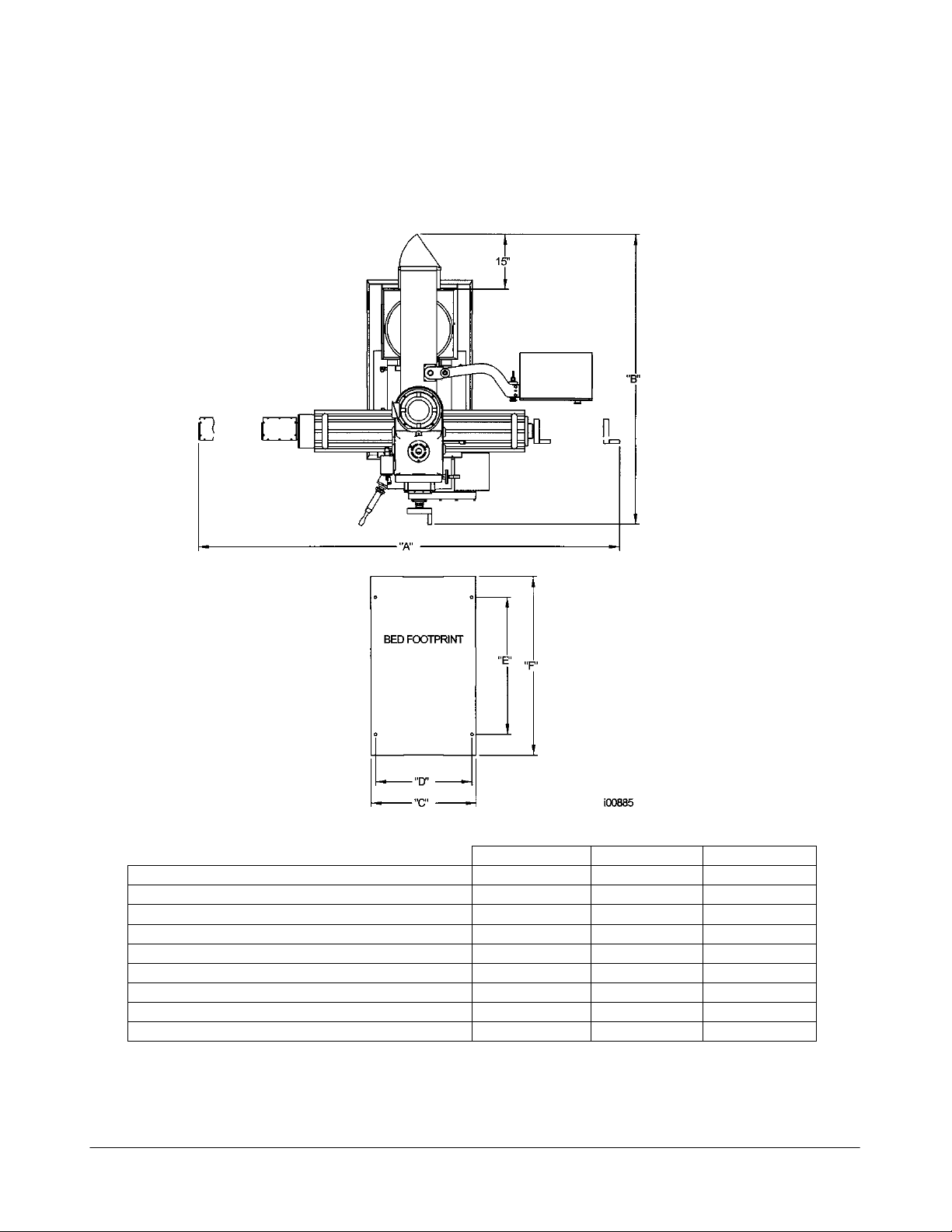
K2
K3
K4
Weight (approximate) net
2200 lbs
2800 lbs
3600 lbs
Weight (approximate) shipping
2500 lbs
3100 lbs
3900 lbs
Pallet Size
6’ x 6’
6’ x 6’
6’ x 6’
A Overall width
101”
103”
103”
B Overall length
66”
70”
72.5”
C Base width
24.2”
24.2”
24”
D Width between leveling screws
21.9”
21.9”
22.8”
E Distance between leveling screws
29.1”
29.7”
33.1”
F Base length
37.4”
38.8”
42.5”
2.0 Installation
Read and understand this entire installation section before beginning the installation procedure.
2.1 Floor Plan, Layout & Space Requirements – K2, K3 & K4
Figure 1 – Machine Footprints
ProtoTRAK SMX, K2, K3 & K4 & Retrofit Safety, Installation, Maintenance, Service and Parts List Manual
6
TRAK Machine Tools
Southwestern Industries, Inc.
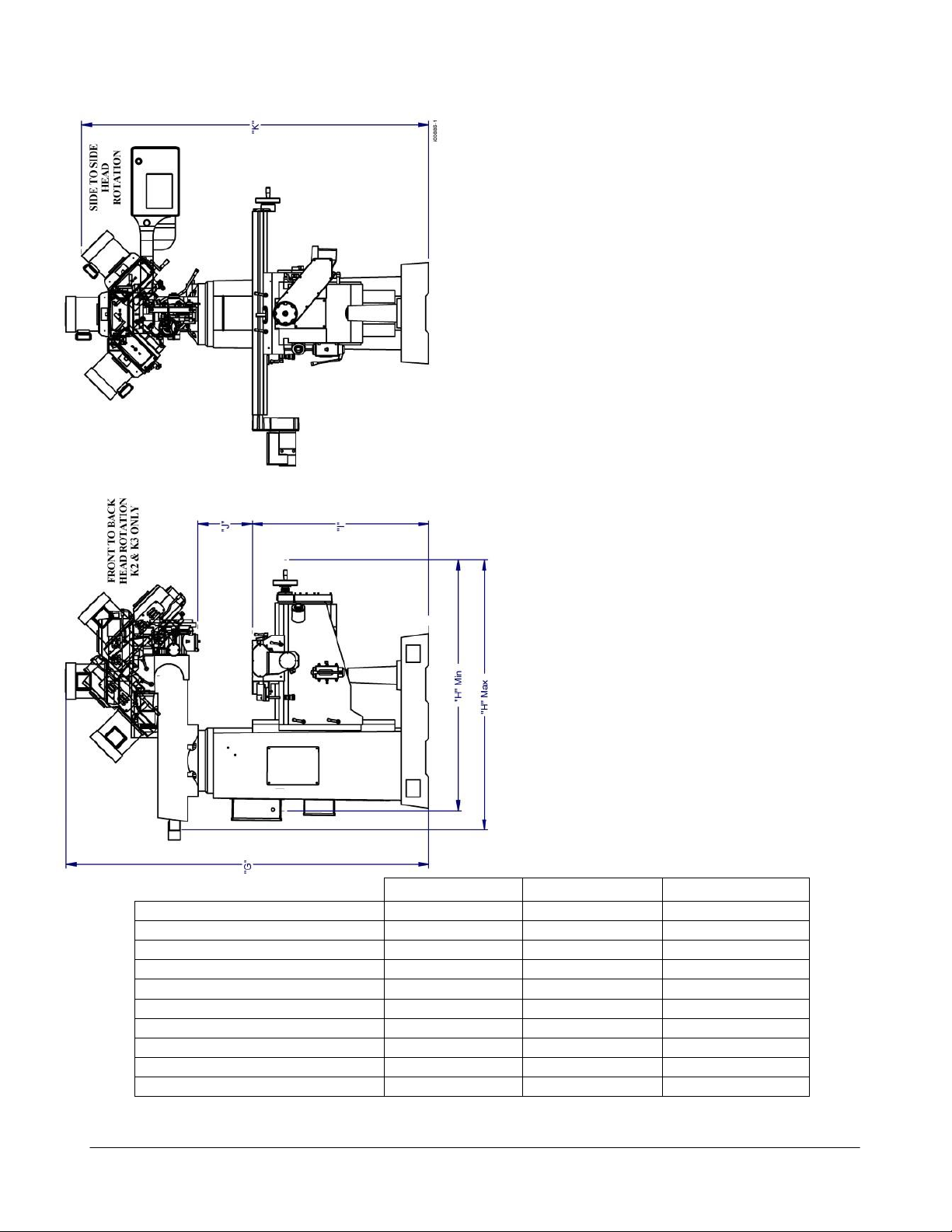
K2
K3
K4
Table Size
9” x 49”
10” x 50”
10” x 50”
T-Slots (number x width)
3” x 5/8”
3” x 5/8”
3” x 5/8”
Dimension G
86”
87”
92”
Dimension G Min
65”
65”
73”
Dimension H Min
56”
64”
64”
Dimension H Max
67”
78”
78”
Dimension I Min
36”
38”
36”
Dimension I Max
49”
49’
54.5
Dimension J Max
18”
17”
23”
Dimension K
69”
69”
77”
Figure 2 – Overall Dimensions
ProtoTRAK SMX, K2, K3 & K4 & Retrofit Safety, Installation, Maintenance, Service and Parts List Manual
7
TRAK Machine Tools
Southwestern Industries, Inc.

ATTENTION!
Immediately report, in writing, any damages observed at this time that can be attributed to the
transportation or improper handling/moving of the machine.
2.2 Uncrating
Carefully remove the wood crate and protective packaging, paying attention not to scratch, damage, or mar any parts of
the machine.
Remove the cardboard boxes with the PENDANT DISPLAY (handle carefully) and the box
containing the TOOL BOX. The leveling pads and screws for the machine can be found in the toolbox. The Y way
covers are shipped in a separate tube.
Loosen and remove 4 screws and nuts holding the machine to the wood pallet.
2.3 Shortages: Inventory Checklist
_____ Machine (check model and serial number)
______ Manual drawbar with washer
______ Leveling pads (FC114), screws (FC112) and leveling nuts (FC113) (4 each)
______ Pendant Display with four 1/4-20 screws for mounting
______ Pendant Arm assembled to the column
______ Toolbox with various tools
______ ProtoTRAK SMX Safety, Operation & Programming Manual (P/N 24493)
______ TRAK K2, K3, K4 & Retrofit Safety, Installation, Maintenance, Service & Parts List
Manual (P/N 24319)
______ Way covers K2 – front of saddle - 20875
______ Way covers K3 & K4 – front of saddle - 20872
______ Way covers K2 – rear of saddle - 20874
______ Way covers K3 & K4 – rear of saddle - 20871
In case of shortages, contact the representative from whom you purchased the machine.
8
ProtoTRAK SMX, K2, K3 & K4 & Retrofit Safety, Installation, Maintenance, Service and Parts List Manual
TRAK Machine Tools
Southwestern Industries, Inc.

1.
Shut off power to the machine.
2.
Visually inspect the 220 or 440V wiring going into the electrical panel. Visually verify the
wiring is correct per our wiring diagram. Make sure a strain relief is being used where the
wiring enters the cabinet. Have the customer repair any wiring discrepancies. Measure the
220 volt and 110 volt input power to make sure it is within specification. If not, notify
customer and report on service report.
3.
Clean the machine if needed and remove any remaining grease.
4.
Unlock the table, saddle, and knee gib locks.
5.
Mount the pendant to the pendant arm using (4) 1/4-20 x 3/4" socket head cap screws.
6.
Make and check all the proper electrical connections from the pendant to the electric box.
See the pendant and electric box wiring diagrams.
7.
On retrofits, place the nameplate serial # plate (21934) on the pendant arm. This serial #
plate is the main system # for that machine. Place the serial # plate using 2 drive screws to
the front of the pendant arm near the pivot point of the arm. Use a #36 drill bit for drive
screws. See figure 57.
8.
On retrofits and TRAK knee mills make sure to plug in the machine ID key on the top corner
of pendant before powering up the pendant. Failure to do so may cause an improper
configuration file. If this happens, go to service code 313 and load the defaults. Loading
defaults will erase any calibration factors that have been done. See pendant connection –
Figure 13.
9.
Turn on the power to the machine and to the pendant.
10.
Load master and slave software from software upgrade disk or USB. The pendant may or may
not have the latest software loaded. (Retrofits only.)
11.
Lubricate all the way surfaces and the ball screws.
12.
Jog the table and saddle back and forth until the way surfaces are well lubricated. Oil should
be visible on all the way surfaces.
13.
Check the level of the machine. The machine should be level to within 0.0005" front to back
and 0.0005" side to side. Even though it is the responsibility of the customer, make any
adjustments if necessary.
14.
Check tram on head and adjust as necessary.
15.
Check to make sure that the E-Stop button is functioning correctly. N/A to retrofits for
spindle.
16.
Perform Service Code 12, Feed Forward Constant.
17.
Perform Service Code 11 to automatically calculate the backlash for the X and Y-axis of glass
scale machines
18.
Perform Service Code 123 to calibrate the X and Y-axis using a 150mm standard.
19.
Perform Service Code 127 and 128 to manually calculate the backlash for the X and Y-axis of
single feedback machines (i.e. motor encoder only).
20.
Check for positional accuracy and repeatability on the X and Y-axis using programs XREPEAT
2 AXIS.PT4 and YREPEAT 2 AXIS.PT4 respectively. Positioning and repeatability values
should be less than or = to 0.0005”. Programs can be found on C drive under the PT4SX
folder followed by the SWI TEST PROGRAMS folder.
21.
For 2 axis machines - perform Service Code 123 and press QUILL softkey to calibrate the Zaxis quill using a 75mm or 3” standard.
22.
For 3 axis machines - perform Service Code 123 and press Z softkey to calibrate the Z-axis
ball screw encoder using a 75mm or 3” standard.
23.
Perform Service Code 100 in both directions for the X, Y, and Z-axis to verify that the feed
rate shown on the display is at least 120 ipm.
24.
Run the spindle at various speeds in both high and low gear for 15 minutes. Verify head
2.4 Installation Instructions & Checklist
Installer: Use this checklist to assure a complete set-up of the K2, K3, K4 or SMX 2 or 3-axis retrofit.
ProtoTRAK SMX, K2, K3 & K4 & Retrofit Safety, Installation, Maintenance, Service and Parts List Manual
TRAK Machine Tools
Southwestern Industries, Inc.
9

shifts from high to low gear smoothly. Test quill feed and spindle brake. N/A to retrofits.
25.
Install the Y-axis front and rear way covers.
26.
Check that all other options that came with machine are installed, functioning or adjusted
properly. They included chip pan, table guard, limit switches, EHW’s, RSG, etc
27.
3 axis machines only - If machine has an auxiliary function option, then use accessory key on
pendant and make sure the coolant pump or solenoid for the mister fires. The accessory key
should be in the ON position to test coolant pump or solenoid. The control should be in DRO
mode. Make sure air is hooked up to the machine during the test. If the machine has a
separate coolant pump switch mounted on the pendant arm then turn this on and off to test.
28.
If the machine has a power drawbar option, check to make sure that the tools load and
unload properly. Verify the drawbar unit is sitting 0.050” to 0.075” above drawbar
shoulder.N/A to retrofits.
29.
Wipe down the machine prior to leaving.
Specifications
K2
K3
K4
Movement and ranges (X, Y, Z axis)
33” x 12” x 16”
32” x 16” x 16”
32” x 16 ½” x
16.5”
Quill Travel (maximum)
5”
5”
5”
Quill Diameter
86 mm
86 mm
100 mm
Spindle Taper
R8
R8
# 40 taper
Speed Range
60-4200 RPM
60-4200 RPM
70-3950 RPM
Optional Spindle Control Speed Range
Low: 40 – 600
Low: 40 – 600
Low: 40 – 600
High: 300 – 5000
High: 300 – 5000
High: 300 – 5000
Spindle to Column
8” to 20”
8” to 32”
7” to 31”
Quill Feeds Per Revolution of Spindle
(Not applicable on three axis)
.0015/.003/.006”
.0015/.003/.006”
.0015/.003/.006”
Head Tilt
+/- 90
+/- 90
+/- 90
Head Swivel
+/- 45
+/- 45
N/A
Spindle Motor Power
3 HP
3 HP
5 HP
Voltage
220/440 V
220/440 V
220/440 V
Machine with Optional Speed Control
220 V
220 V
220 V
Phase/Cycle
3 phase/60 Hz
3 phase/60 Hz
3 phase/60 Hz
Current- Non Spindle Control
8.5/4.3 amps
8.5/4.3 amps
14/7 amps
Current – Spindle Control
11 amps
11 amps
17.5 amps
Maximum Weight of Workpiece
750 lbs
850 lbs
850 lbs
Coolant Capacity
9 gallons
9 gallons
9 gallons
K2/K3
K4
Drilling Mild Steel (2-axis manual feed)
1 ¼”
1 ½”
Tapping Mild Steel
1”
1”
Milling (metal removal rate/mild steel)
1 ½ inch3/min
2 inch3/min
Drilling (3-axis systems)
½”
½”
2.5 Machine Specifications
2.6 Maximum Work Capacities
Maximum work capacities are dependent on a lot of variables that cannot be controlled by the machine manufacturer.
Each one of the following will have an impact on the above numbers: speeds, feeds, cutter, cutter sharpness, material,
setup, coolant and machine adjustments. The numbers above assume all conditions are optimal and may be higher or
lower depending on material composition.
ProtoTRAK SMX, K2, K3 & K4 & Retrofit Safety, Installation, Maintenance, Service and Parts List Manual
TRAK Machine Tools
Southwestern Industries, Inc.
10

2.7 ProtoTRAK SMX Control Hardware
2 or 3-axis CNC, 3-axis DRO
400 PC-based processor
256 MB of RAM
D.C. Servo Motors rated at 280 in-oz continuous torque for X, Y and Z-axes
Precision ground ballscrews in the table and saddle to ensure smooth accurate contours without backlash
Feedrate override of programmed feedrate and rapid
Polycarbonate sealed membrane and gasket sealed control enclosure to lock out contamination
10 ½" color LCD for clear presentation of prompts, status information and part graphics
Modular design simplifies service and maximizes uptime
256 MB flash drive
Single floppy disk drive for additional part program storage
Optional auxiliary function box for control of coolant pump or spray mist coolant, spindle off and a
programmable rotary table or indexer – 3 axis machines only
11
TRAK Machine Tools
Southwestern Industries, Inc.
ProtoTRAK SMX, K2, K3 & K4 & Retrofit Safety, Installation, Maintenance, Service and Parts List Manual
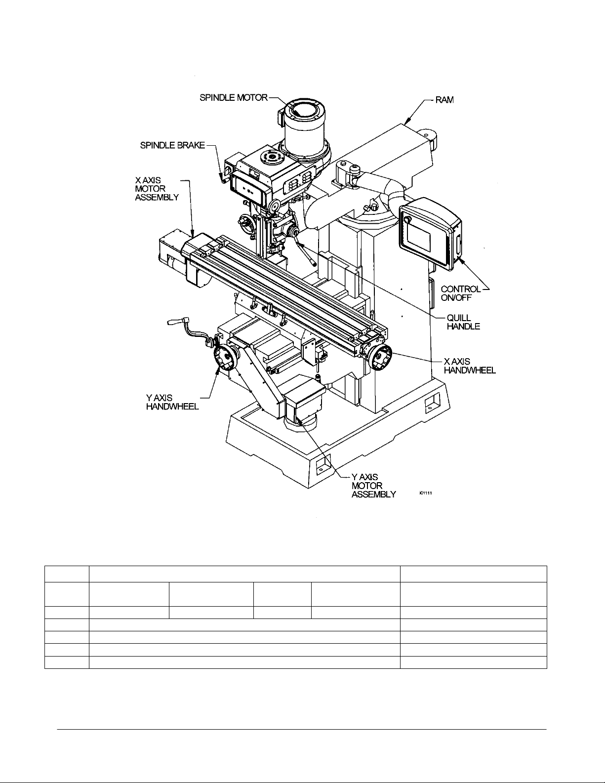
Figure 3 & Parts List Shown
Knee Mill Component Identification
Item
Part Number
Description
SMX K2 + K3
SMX K2 + K3
Spindle Control
SMX K4
SMX K4
Spindle Control
1
20819
24162
20820
24163
Spindle Motor
2
24000-1
SMX Pendant
3
15616
Y-Axis Handwheel (Saddle)
4
15616
X-Axis Handwheel (Table)
5
20296
X, Y or Z Motor
ProtoTRAK SMX, K2, K3 & K4 & Retrofit Safety, Installation, Maintenance, Service and Parts List Manual
Southwestern Industries, Inc.
12
TRAK Machine Tools
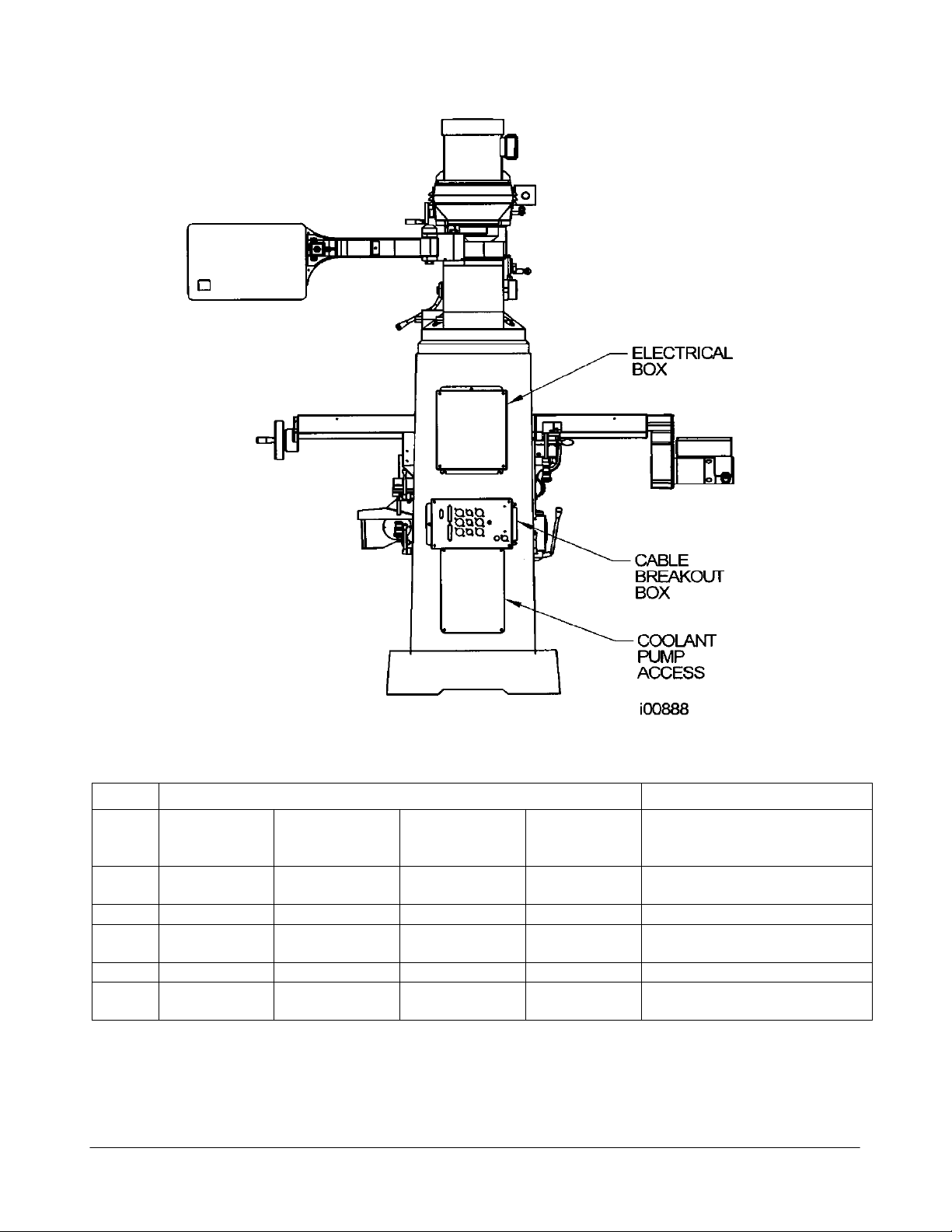
Figure 4 & Parts List Shown
Knee Mill Rear View
Item
Part Number
Description
SMX K2/K3
SMX K2/K3
Spindle Control
SMX K4
SMX K4
Spindle
Control
1
220V=20676
440V=20676
24060-1
220V only
220V=20676-1
440V=20676
24060-2
220V only
Electrical Box
2
24999
24999
24999
24999
Cable Breakout Box
3
24999-1
24999-1
24999-1
24999-1
Cable Breakout Box with AUX
Functions
4
9001
9001
9001
9001
Lube Pump
5
20676-2
N/A
20676-2
N/A
Electrical box
(if have tableguard option)
ProtoTRAK SMX, K2, K3 & K4 & Retrofit Safety, Installation, Maintenance, Service and Parts List Manual
13
TRAK Machine Tools
Southwestern Industries, Inc.

CAUTION!
The K2, K3 & K4 machines weighs approximately 2200, 2800 & 3600 lbs respectively.
Proper equipment of sufficient capacity must be used when lifting and/or moving the
machine.
2.8 Lifting and/or Moving the Machine
(See Figure 5 To Prepare the Mill before Lifting):
1. Using a steel cable with protective sleeving (min 3/4” diameter) or a 3-ton
sling, position sling loops on machine as shown in Figure 5.
2. Use cardboard pieces or other suitable protective sheets on both sides of
the machine to prevent scratching.
3. Remove the 4 nuts and screws holding the machine to the wood skid.
4. Lift the machine (the machine should lift approximately level).
5. Insert the 4 screws for leveling pads in their place in the bed.
6. Place the machine in its location (see floor plan and bed footprint drawing),
carefully positioning each leveling pad under each leveling screw.
7. Remove the lifting cable or sling and all protective cardboard.
14
ProtoTRAK SMX, K2, K3 & K4 & Retrofit Safety, Installation, Maintenance, Service and Parts List Manual
TRAK Machine Tools
Southwestern Industries, Inc.

Figure 5
Lifting the Machine
ProtoTRAK SMX, K2, K3 & K4 & Retrofit Safety, Installation, Maintenance, Service and Parts List Manual
15
TRAK Machine Tools
Southwestern Industries, Inc.

WARNING!
Do not use gasoline or other flammable cleaning agents for cleaning the machine.
CAUTION!
Never move any of the above parts over ways that were not previously cleaned.
Serious damage to the TURCITE surface of slideways can occur.
2.9 Cleaning
1. Remove rust protective coating from the machine before moving any slideways (table, saddle, knee, etc.).
2. The coating is best removed with clean, dry rags. Do not use a cleaning solution that may damage the rubber
way scrapers, plastic parts, or paint.
3. It may be necessary to move back and forward, left and right, and up and down the table, saddle and the ram. Always release the clamp
levers (two in front of the table, one underneath the saddle on each side, and two ram lockbolts on the
right side of the column) before attempting to move the above parts.
4. Be certain the table, saddle and spindle move freely and smoothly over their entire length.
2.10 Leveling: Leveling Tolerance is .0005”/10”
1. Set the machine on its 4 leveling pads on a solid, level floor prepared in accordance with the state and local
rules for machine tool installation.
2. Put one or two precision Spirit Levels or Electronic Levels in the center of the table in the positions illustrated in
Figure 6.
3. Adjust the 4 corner leveling screws on their pads until the machine is level to .0005 in/10 in.
4. If the machine must be anchored to the floor, follow the general instruction for installing machine tools and use
for leveling any well-known methods: shims, etc.).
5. If the machine must be installed on vibration mounts/pads (rubber, commercially available leveling and vibration
mounts, etc.) follow the instructions delivered with the mounts/pads, ordering them to satisfy the load of the
machine and the maximum weight of the work piece.
6. When machine is correctly level, lock the adjusting screws in place with their hex nuts.
16
TRAK Machine Tools
ProtoTRAK SMX, K2, K3 & K4 & Retrofit Safety, Installation, Maintenance, Service and Parts List Manual
Southwestern Industries, Inc.
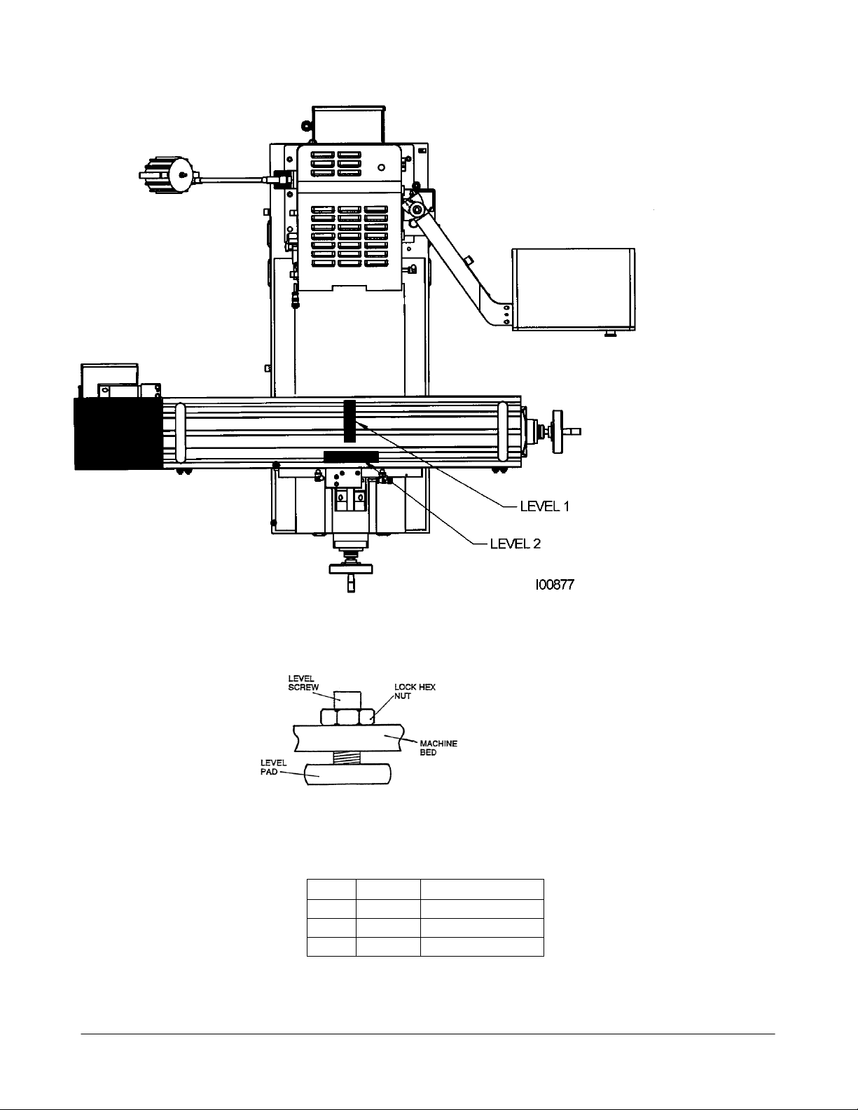
I00138
Item
P/N
Title
1
FC112
LEVEL SCREW
2
FC113
LOCK HEX NUT
3
FC114
LEVELING PAD
i00138
Placement of Levels
Figure 7 & Parts List Shown
Leveling Screws
Figure 6
17
TRAK Machine Tools
Southwestern Industries, Inc.
ProtoTRAK SMX, K2, K3 & K4 & Retrofit Safety, Installation, Maintenance, Service and Parts List Manual

DANGER!
Be certain that 200-volt electricity (typical range 208 – 240V) is used only with a
machine labeled 220 volts at the motor and at the electrics box on the back of the
column. Be certain that 400-volt electricity (typical range 415 - 460V) is used only
with a machine labeled 440 volts at the motor and at the electrics box on the back of
the column.
DANGER!
The 220 or 440-volt line must originate from a dedicated and independent fused box
with a manual shut-off lever. It is the responsibility of the purchaser to supply a
wired box that meets all local codes and regulations.
DANGER!
Only a qualified electrician should wire the 220 or 440-volt 3-phase electricity.
2.11 Electrical Connection
The TRAK K2, K3 & K4 Knee Mills can be configured for 220 or 440 volt 3 phase electricity. These machines also require
a 110V power source to power the control. NOTE: Machines with Optional Spindle Control is only available in
220 V configurations.
Incoming 220 or 440-volt power connects to the machine through the electrical box located on the back of the
column. The power cable enters the black box through a hole on the top of the box.
To convert a K2 or K3 machine from 220 to 440 volt power or vice versa 3 things must happen: spindle motor must
be rewired, overload relay must be set to 8.5 amps for 220 V and 4.25 for 440 volts and the voltage stickers on the
electric’s box must be replaced.
To convert a K4 machine from 220 to 440 volt power 3 things must happen: spindle motor must be rewired,
overload relay must be replaced and set to 14 amps for 220 V and 7 for 440 volts and the voltage stickers on the
electric’s box must be replaced.
NOTE: Voltage conversion from 220V to 440V not applicable to machine fitted with the Spindle Control Option.
See Section 5.1.12 for a diagram of how to rewire the spindle motor.
TRAK Machine Tools recommends the machine be earth grounded by driving a copper rod into the ground. It is the
responsibility of the customer to install this rod.
ProtoTRAK SMX, K2, K3 & K4 & Retrofit Safety, Installation, Maintenance, Service and Parts List Manual
Southwestern Industries, Inc.
TRAK Machine Tools
18
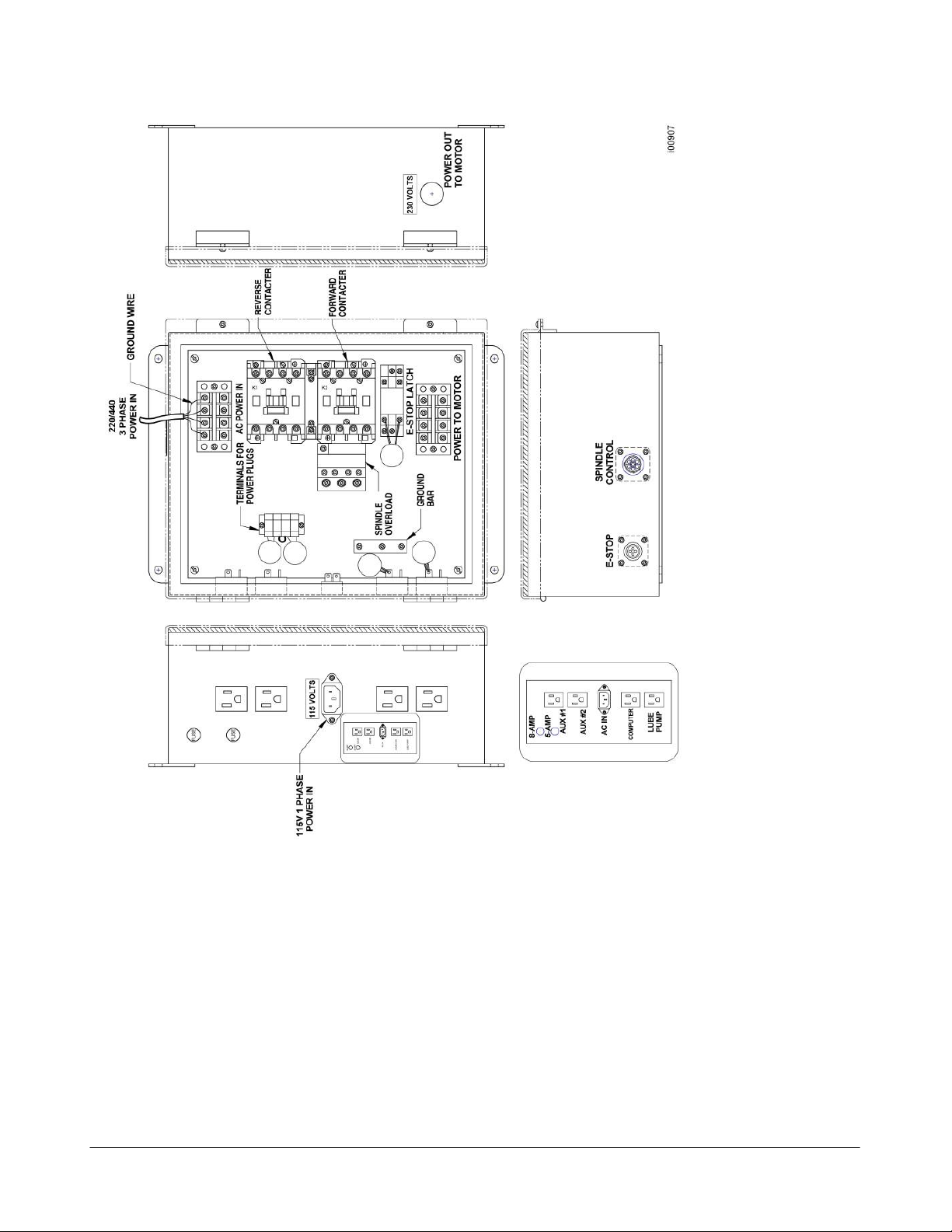
Figure 8
Wiring K2, K3, or K4 – Non Spindle Control – Not for Retrofit
19
TRAK Machine Tools
ProtoTRAK SMX, K2, K3 & K4 & Retrofit Safety, Installation, Maintenance, Service and Parts List Manual
Southwestern Industries, Inc.

NOTE: If equipped with Table Guard Option, the Electrical Box the P/N is 20676-2
Part Number
Description
K2/K3/K4
220V & 440V = 20676
Electrical Box
220V & 440V = 23438-3
Overload
23436
Contactor (Qty = 2) (Reverse or Forward)
Item
Part Number
Description
K2/K3
K4 1
24060-1
24060-2
Electrical Box
5
22890-500-120
22890-500-64
Resistor (Qty = 2)
8
25105K2/K3SX
25106-K4SX
AC Drive - Mini Vector - 220V
12
22961
Relay - Power - 115V DPST
14
21824-5
Fuse - 3 AG - Slow Blow 5 AMP
15
21824-8
Fuse - 3 AG - Slow Blow 8 AMP
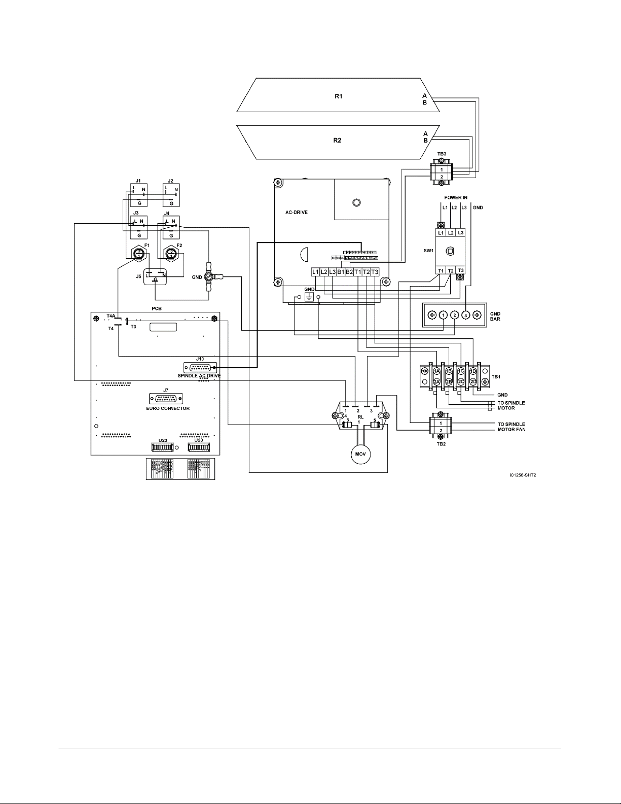
Figure 9 & Parts List Shown
Wiring the K2, K3 or K4 – Spindle Control
See Figure 117 in the rear of the manual for a more detailed breakdown of parts.
TRAK Machine Tools recommends the machine be earth grounded by driving a copper rod into the ground. It is the
responsibility of the customer to install this rod.
20
ProtoTRAK SMX, K2, K3 & K4 & Retrofit Safety, Installation, Maintenance, Service and Parts List Manual
TRAK Machine Tools
Southwestern Industries, Inc.
TO
TO
TO
Figure 9-1
Wiring the K2, K3 or K4 – Spindle Control
2.11.1 Phase Converters
For those machines that will be run with a phase converter it is recommended that it is a rotary type rather than a
static phase converters. Rotary phase converters allow for varying loads in the system. The electrical load on the
machine will vary based on the type of cut taken. Static phase converters can only be used on machines with a nonvarying load. The phase converter for the K mill machines must be rated at a minimum of 5 KVA for the K2 and K3
and 7 KVA for K4.
2.11.2 Flange Disconnect/Transformer (Optional)
The Flange Disconnect Option eliminates the need for the user to provide a power disconnect for the machine on
their own, while the Transformer Option allows the user to provide one power source to the machine. Note: This
option is not available to machine fitted with the Spindle Control Option.
21
TRAK Machine Tools
Southwestern Industries, Inc.
ProtoTRAK SMX, K2, K3 & K4 & Retrofit Safety, Installation, Maintenance, Service and Parts List Manual
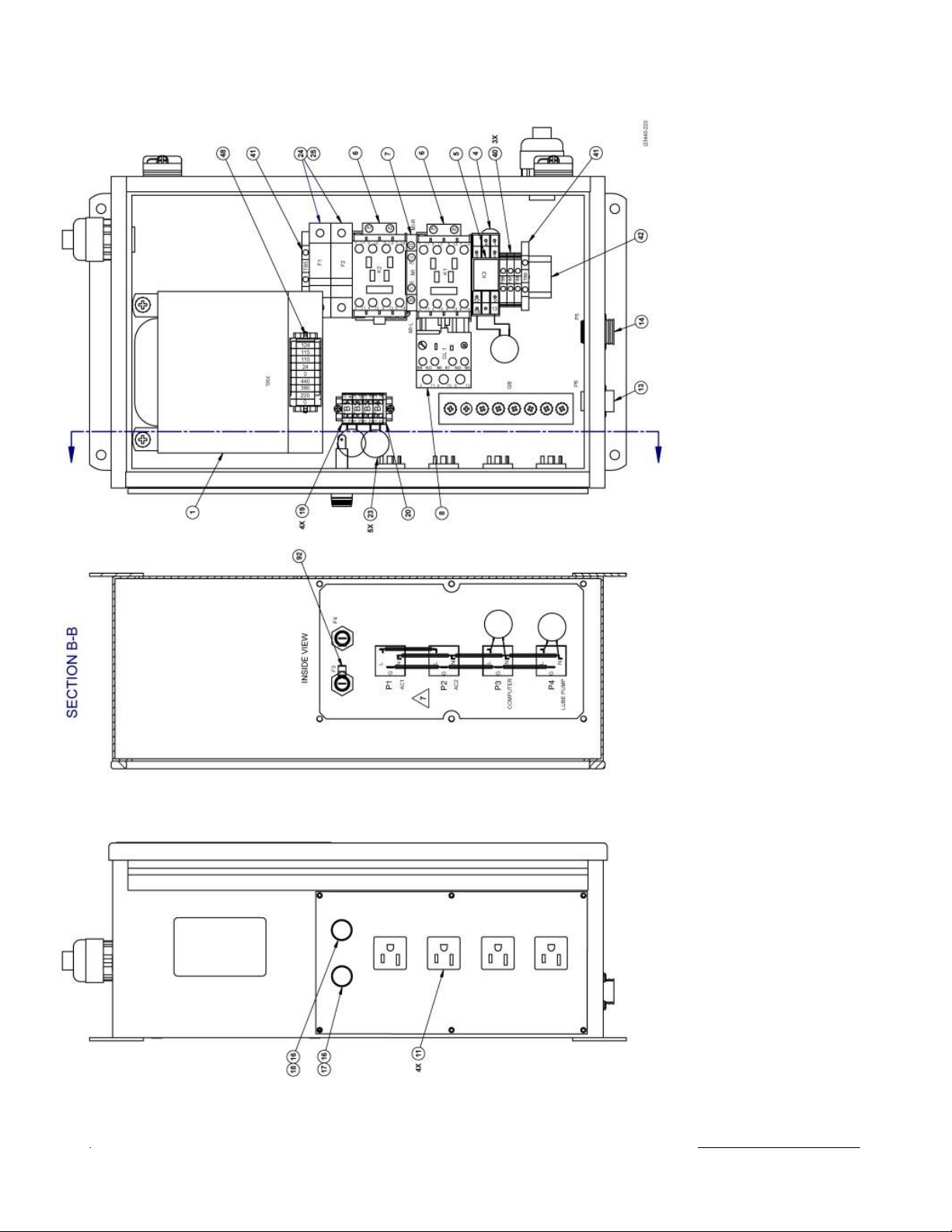
Figure 10 – Flange Disconnect/Transformer Option
P/N 23440-220, 23440-1-220, & 23440-440
22
TRAK Machine Tools
ProtoTRAK SMX, K2, K3 & K4 & Retrofit Safety, Installation, Maintenance, Service and Parts List Manual
Southwestern Industries, Inc.

Item
P/N
Title
Qty
1
21258
TRANSFORMER 1000VA EI
1 4 23434
SOCKET-RELAY
1
5
23435
RELAY-POWER-100-120 VAC-DPDT
1
6
23436
CONTACTOR-4 POLE
2 7 23437
MECHANICAL INTERLOCK
1
8
23438
OVERLOAD RELAY-440V
1
9
23438-1
OVERLOAD RELAY-220V
1
11
22199-1
RECEPTACLE- PANEL MOUNT NEMA STD 15A 125V
4
13
21871
CONNECTOR-4 POSITION-SIZE 11
1
14
23297-1
CONNECTOR-REVERSE SEX-13-7-CPC
1
16
21820
FUSE HOLDER
2
17
21824-5
FUSE-3AG-SLOW BLOW
1
18
21830-12
FUSE-TYPE 3AB-12A-SLO BLO
1
19
22868
TERMINAL BLOCK
4
20
22869
END PLATE
1
22
21753-3
GROUND BAR- 6 HOLE
1
23
21901-150
MOV-V150LA20B
5
24
23036
FUSE HOLDER-32 AMP-690V
2
25
23153-3
FUSE-600 VAC-TIME DELAY-CLASS CC
2
26
22303-16G
WIRE-BUSS-16 GA AWG 12" STRAIGHT
12.25
40
22557-1
TERMINAL BLOCK - 6mm BLOCK
3
41
24299-3
TERMINAL BLOCK-RAIL END STOP/ GROUND
2
42
22571-8.125
RAIL-DIN
8.13
45
23429
SHEETMETAL-COVER PLATE LEFT-PT4-SM TRANSFORMER OPTION
1
48
24407
NAMEPLATE - TRANSFORMER
1
i23440-220
Parts List – Flange Disconnect/Transformer (Figure 10)
TRAK Machine Tools
Southwestern Industries, Inc.
ProtoTRAK SMX, K2, K3 & K4 & Retrofit Safety, Installation, Maintenance, Service and Parts List Manual
23
 Loading...