

Trakm8 T10-Micro, T10-Lite Installation Manual
T10 Installation Notes v1.7
Generic T10 Installation Notes v1.7.doc 12.08.2015
Page 1
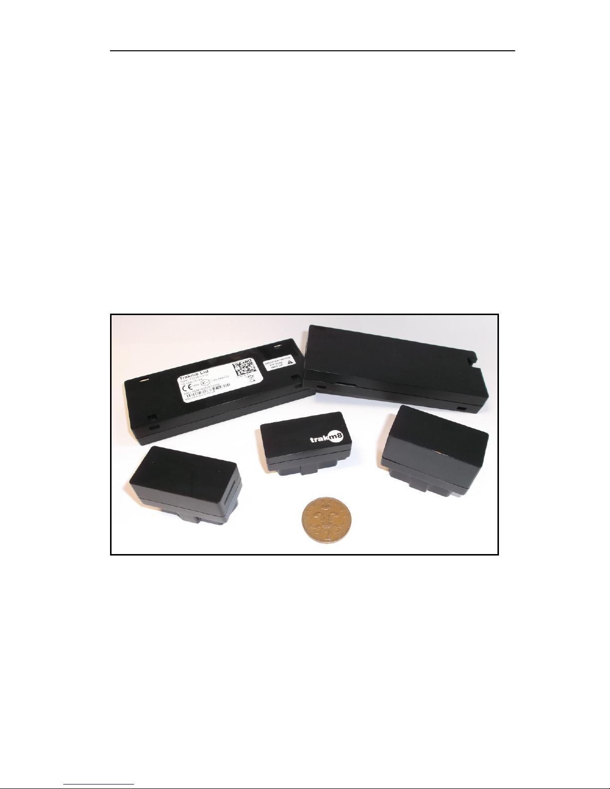
T10 Family
Installation Notes
T10 & Derivatives
For Cars, Car Derived Vans,
And Light Commercial Vehicles

T10 Installation Notes v1.7
Generic T10 Installation Notes v1.7.doc 12.08.2015
Page 2
Table of Contents
1 Contact Information 3
2 Document Revision History 4
3 Preface 5
3.1 Safety Information .....................................................................................................5
Product Certification ............................................................................................................6
4 The T10 Family 8
4.1 T10-Micro..................................................................................................................8
4.2 T10-Lite ....................................................................................................................8
5 Installation 8
5.1 T10-Lite Variants .......................................................................................................8
5.2 SIM Card ................................................................................................................. 10
5.2.1 Before fitting the SIM card ................................................................................. 10
5.2.2 Fitting the SIM card .......................................................................................... 10
5.3 Backup Battery ........................................................................................................ 11
5.4 Mounting the T10-Lite .............................................................................................. 11
5.5 T10-Lite Wiring and Connections .............................................................................. 11
5.5.1 Cables and Accessory Options ............................................................................ 12
5.5.2 Power Ground and Ignition Installation .............................................................. 12
5.5.3 Driver Interface Button Installation (T10-Lite 9wire ONLY) .................................. 15
5.5.4 Dallas I-Button Installation (T10-Lite 9wire ONLY) .............................................. 16
5.5.5 Inputs Installation (T10-Lite 9wire ONLY) ........................................................... 17
5.5.6 Output Installation (T10-Lite 9wire ONLY) .......................................................... 18
5.5.7 Immobiliser Feature (T10-Lite 9wire ONLY) ........................................................ 18
5.5.8 CAN Installation – Vehicle (T10-Micro v4, T10-Lite 5wire & 9wire) ....................... 19
5.5.9 Cable Assemblies .............................................................................................. 21
5.5.10 Engineering Mode ............................................................................................. 22
Appendix A –T10 Records 24
Appendix B – Abbreviations and Glossary Of Terms 25

T10 Installation Notes v1.7
Generic T10 Installation Notes v1.7.doc 12.08.2015
Page 3
1 Contact Information
All initial communication or enquiries should be made to:
Trakm8 Limited
Lydden House
Wincombe Business Park
Shaftesbury
Dorset
SP7 9QJ
UK
International Tel: +44 (0) 1747 858444
International Fax: +44 (0) 1747 858222
E-mail support@trakm8.com

T10 Installation Notes v1.7
Generic T10 Installation Notes v1.7.doc 12.08.2015
Page 4
2 Document Revision History
Document
Issue
Date of Issue
Reason/Description of Change
1.0
1.1
1.2
1.3
1.4
1.5
1.6
1.7
4th April 2014
5th January 2015
3rd March 2015
11th March 2015
12th March 2015
25th March 2015
23rd April 2015
12th August 2015
Draft Issue.
First Release includes T10-Micro, T10 MiniLite and T10 Lite.
Second Release
Includes additional accessories and abbreviations
Additional Safety, temperature and Battery information
Product name references T10-Lite updates.
Additional T10-Lite updates, K-Line and FCC/IC information.
Additional FCC, IC, VCA and K-line user information

T10 Installation Notes v1.7
Generic T10 Installation Notes v1.7.doc 12.08.2015
Page 5
3 Preface
Failure to comply with the following Warnings, Approval and Safety information
may invalidate warranty, certification or type approval of this product.
1. WARNING!
Current FCC and regulations limit the EIRP of mobile devices to 2 W.
A 20 cm (7.87 inch) separation distance between the T10 unit and all persons must be
maintained at all times.
“To comply with Industry Canada RF radiation exposure limits for general population,
the antenna(s) used for this transmitter must be installed such that a minimum
separation distance of 20cm is maintained between the radiator (antenna) and all
persons at all times and must not be co-located or operating in conjunction with any
other antenna or transmitter.”
2. Any attempt to make modifications not expressly approved by Trakm8 may invalidate the
warranty and the user’s authority to use the equipment.
3. Unauthorised modification to this equipment or associated accessories is forbidden without
the express permission and agreement from the product manufacturer.
4. This equipment should not be operated in hazardous environments i.e. areas that contain
explosive materials or flammable vapours.
5. This equipment should not be operated within aircraft or in close proximity to medical
equipment.
6. Internal components containing beryllium oxide may be used in this equipment. Dust from
this material is a health hazard if inhaled or allowed to come into contact with the skin. Great
care must be taken when handling these components.
7. This equipment is restricted to temperature ranges depending on the build spec of the
hardware:
a. -40C to +85C (if not fitted with Backup battery)
b. 0C to +45C (if fitted with backup battery)
The unit will still operate outside of these limits but the battery charging circuitry will
be inhibited to protect the battery.
3.1 Safety Information
Please adhere to the following Safety and Installation information at all times.
T10-Micro 2 Tier Supply Voltage: +6V minimum to +15V maximum.
T10-Micro 1/3 tier Supply Voltage: +6V minimum to +30V maximum.
T10-Lite Supply Voltage: +6V minimum to +30V maximum.
T10-Micro 1/2/3 Tier Current at: 12V/24V <= 500mA – fit a 2A inline fuse.
T10-Lite Current at: 12V/24V <= 500mA – fit a 2A inline fuse.
T10-Micro/T10-Lite Battery charging peak < 1 Amp at 12V.
T10-Micro/T10-Lite Battery charging peak < 1 Amp at 24V.
Note: Fuses should be placed in all power lines as close as possible to the vehicle supply source.
(Supply fuse: 2A, Ignition Fuse: 1A) These are supplied as an integral part of the T10 cable
range: (CAB400, CAB405, CAB410, and CAB415).
The currents indicated above are worst case scenario when the device is transmitting at peak
power and are typically a lot lower than shown.
NB Important - The telemetry unit’s power supply for the vehicle installation MUST utilise a
permanent power feed that is NOT subject to battery isolation ‘kill switch’ technology. If the
vehicle is fitted with battery isolation ‘kill switch’ technology, then the permanent power feed
MUST be taken directly from the vehicles battery terminals or the permanently powered terminal
T10 Installation Notes v1.7
Generic T10 Installation Notes v1.7.doc 12.08.2015
Page 6
of the isolation switch. If the battery isolation device is a negative earth isolator, the –Ve Ground
connection must be taken from a chassis earth point to prevent potential feedback through the
telemetry unit when the isolation switch is activated.
The commissioning desk MUST be informed if the vehicle has a negative earth isolation switch
fitted as an internal battery backup unit may be required to be fitted during the installation process
if one is not supplied as standard.
NB.* All electrical connections should be checked and confirmed with the use of a multi-meter.
THE RATINGS OF THESE FUSES SHOULD NOT BE EXCEEDED AT ANY TIME
WARNING!
This equipment may only be located in a position where it cannot interfere with
the normal operation of the vehicle or present a hazard to the driver or
passengers. Care must also be taken in the routing of all cables so that the
insulation does not become worn or damaged.
Product Certification
The product can be marketed within the European Community.
Below are the approval references:
European Approval
R&TTE Directive 1999/5/EC
Trakm8 Limited hereby declares that the T10-Micro and T10-Lite are in compliance
with the essential requirements and other relevant provisions of Directive 1999/5/EC
(R&TTE Directive).
As part of the requirements of the R&TTE directive the T10-Micro and T10-Lite have
been designed to operate on the European GSM 900 MHz and DCS 1800 MHz GSM/GPRS
frequency bands.
The T10-Micro and T10-Lite products are compliant with the following standards
and/or normative documents:
EN60950-1: 2006 / A11: 2009 / A1: 2010 / A12: 2011, EN62311: 2008, EN301489-1: V1.9.2 :
2011, EN301489-3: V1.4.1 : 2002, EN301489-17: V2.1.1 : 2009, EN300328: V1.7.1 : 2006,
EN300440-2: V1.4.1 : 2010, EN300220-2: V2.3.1 : 2010, EN301511: V9.0.2 : (2002-11).
The declaration of conformity (DOC) can be supplied on application or downloaded from
our web site at www.trakm8.com.
CE – marking (T10-Micro and T10-Lite)
The T10-Micro and T10-Lite products contain a u-blox SARA G340/G350 radio module
whose associated Notified Body number is 1909. The product contains the following
marking:
T10 Installation Notes v1.7
Generic T10 Installation Notes v1.7.doc 12.08.2015
Page 7
USA and Canada Approval
FCC – Marking (T10-Micro)
The T10-Micro complies with Part 15 of the FCC Rules and contains the following
markings.
FCCID:SMGT10MICROBLE
Operation of the product is subject to the following two conditions:
1. This device may not cause harmful interference.
2. This device must accept any interference received, including interference that
may cause undesirable operation.
IC – Marking (T10-Micro)
The T10-Micro complies with Industry Canada licence exempt RSS Standard(s) and
contains the following markings:
IC:20171-T10MICROBLE
Operation of the product is subject to the following two conditions:
1. This device may not cause harmful interference.
2. This device must accept any interference received, including interference that
may cause undesirable operation.
VCA Approval
“E” – Marking (T10-Micro 2 Tier)
The T10-Micro has been approved by the VCA directive for automotive use in
accordance with EMV 2004/104/EG and contains the following marking:
“E” – Marking (T10-Micro 3 Tier)
The T10-Micro 3 Tier is currently undergoing approvals.
“E” – Marking (T10-MiniLite/T10-Lite 3/5 wire)
The T10-Lite 3/5 wire has been approved by the VCA directive for automotive use in
accordance with EMV 2004/104/EG and contains the following marking:
This product was formerly known as T10-MiniLite and has now been bannered under the
T10-Lite group as a 3 wire or 5 wire device.
“E” – Marking (T10-Lite 9 wire)
The T10-Lite 9 wire has been approved by the VCA directive for automotive use in
accordance with EMV 2004/104/EG and contains the following marking:

T10 Installation Notes v1.7
Generic T10 Installation Notes v1.7.doc 12.08.2015
Page 8
4 The T10 Family
The T10 family consists of a range of products to meet the demanding requirements of modern
day telematics.
In summary these variations have been categorised into two sub families called:
a. T10-Micro
b. T10-Lite (2/3/5/9 wire)
4.1 T10-Micro
The T10-micro is a plug and play product designed to be inserted into the vehicle ECU Diagnostic
socket (J1962) which usually is accessible within the driver cockpit area and can be accessed
without the need of specialised tools. This product does not require the involvement of a
specialised fitter and can usually be fitted by the end user. Units that are supplied with a
customer SIM fit option should follow the same SIM fitting process as described for the T10-Lite.
4.2 T10-Lite
The T10-Lite exists as 4 variants (2wire, 3wire, 5wire, 9wire) and requires the specialised
knowledge of fitting electrical equipment to vehicles. The T10-Lite 2/3/5wire devices (formerly
known as T10-MiniLite) which are very similar in size to the T10-Lite 9 wire product but contain
the following additional hardware features over the T10-Lite 2/3/5wire device:
1. A larger backup battery (1500mAH).
2. Addition of a Driver Interface Button (Cable CAB601).
3. Addition of a Driver Identification Dallas interface (Cable CAB700).
4. Addition of an Output to drive an immobilisation relay.
5. Addition of a PTO Input (NONE CAN variant ONLY).
6. Additional CAN Protocols (ISO 9041, KW2000)
5 Installation
5.1 T10-Lite Variants
Before you begin installing and commissioning the system please ensure that you have read this
manual thoroughly referring to any supplementary information provided for the T10 as required.
This document covers the T10 platform Control Unit and its connections through the following
process:
1. Recommended Sequence
2. Fitting the SIM
3. Mounting the Unit
4. Wiring and connections
i. Power, Ground and Ignition (ALL variants ex 2wire – Power/Ground ONLY)
ii. CAN (T10-Lite 5 wire & 9wire)
iii. Driver Button (T10-Lite 9 wire ONLY)
iv. Driver Identification (T10-Lite 9 wire ONLY)
v. PTO Input (T10-Lite 9 wire ONLY)
vi. Output (T10-Lite 9 wire ONLY)
 Loading...