


FluidSecure
Installation
Instructions
Installation, Operation and Safety Manual
Trak Engineering, Inc. ▲ Tallahassee, Florida 32301
850-878-4585 ▲ support@trakeng.com
www.fluidsecure.com ▲www.trakeng.com

1 | P a g e
Safety Information
Warning! All wiring should be installed in accordance with local, state and national
electrical code requirements under NEC/ANSI/NFPA 70. IMC threaded conduit, sealed
fittings and proper electrical wiring practices should be adhered to. Improper installation
can result in fire, serious bodily injury or death.
Warning! Pay attention to the following safety practices.
1) Never smoke or use an open flame anywhere near the tanks or dispensers.
2) All mechanical joints containing fuel products must be sealed with sealant tape
appropriate for the product dispensed.
3) Never use any tools near the dispenser or tanks that can create unexpected sparks
4) Always have a fire extinguisher available in case of fire
5) Always turn off all electrical power when working on any pumps or dispensers.
6) It is highly recommended that someone who is capable of rendering first aid be
present during the installation process
7) Follow OSHA lockout/tagout procedures during installation, service and
maintenance.
8) Know where the emergency shutoff is located. Do not use emergency stops to
disconnect electrical power. Always disconnect at the breakers.
9) Always cordon off all work areas from vehicle traffic.
10) The State of California cautions that fuel and fuel handling systems contain
chemicals that are known to cause cancer or reproductive harm.
2 | P a g e
FluidSecure Link Performance Specifications
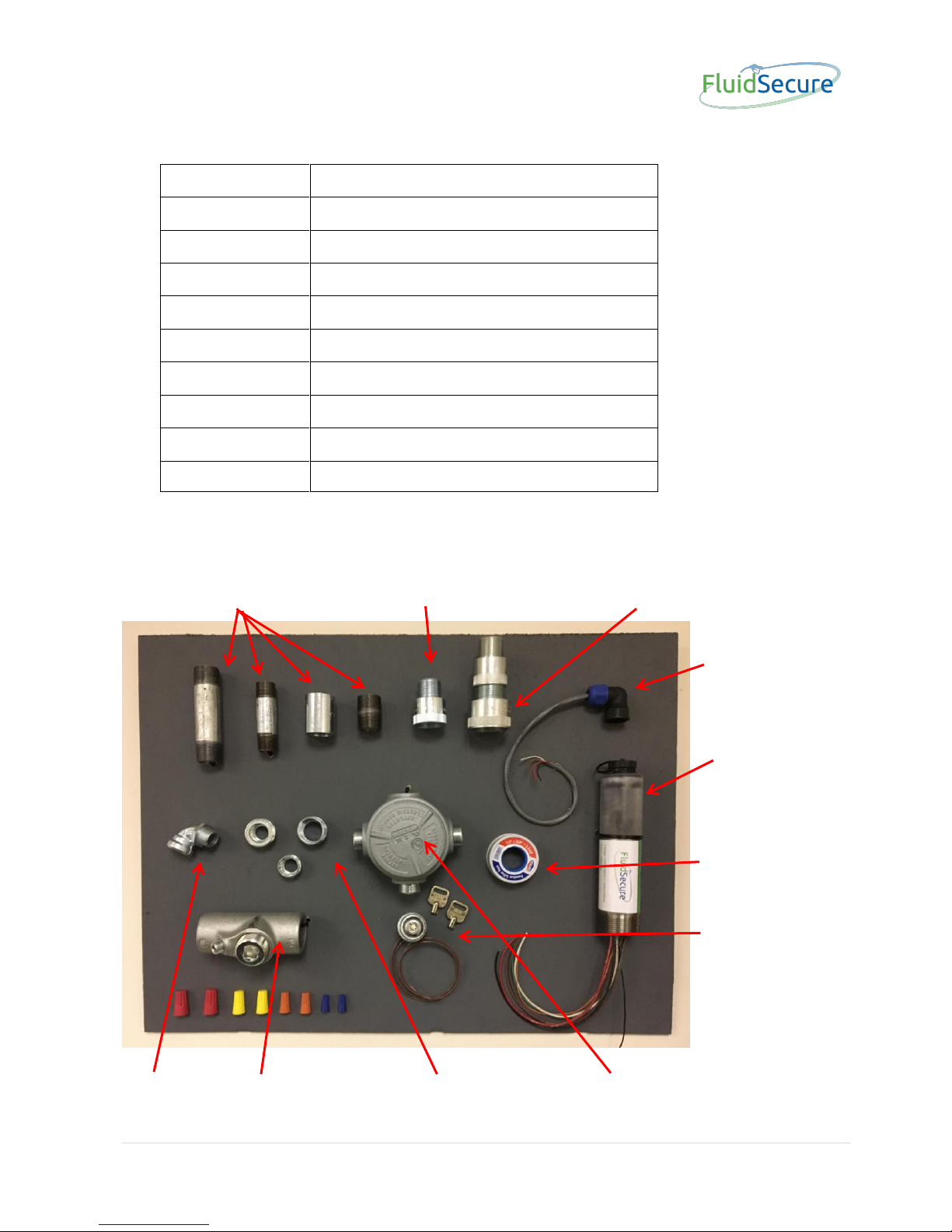
The picture below shows the parts that are included with a FluidSecure kit.
Conduit Nipples 1” to 3/4” Reducing Adapter 11/4” to 1” Reducing Adapter
Pulser Cable
(External)
LINK
Pipe Tape
Manual Override
Switch and Keys
90 Elbow 1” Sealoff Various Reducing Bushings 3/4” 5 way Junction Box
Voltage
115VAC, 230VAC, 12VDC, 24VDC
Power (Link)
1.5 watts
Control
Maximum 3/4hp motor
Pulser Input
Dry reed switch or Open Collector
Link Comm
WiFi 802.11
Temp
-40 to +80 C (-40 to 176 F)
Class
Class 1, Div. 1
Listing
Pending
Flow Pulser
+/- 2%
External Pulser
Pulser dependent
3 | P a g e
A: Installation - Above Ground Tank
FluidSecure LINK is designed to work with virtually any electrically operated
dispenser, pump or solenoid. There are a large variety of dispensing systems and
electrical connections and methods of connecting such devices together. It is not the
intention of this manual to cover all possible combinations of connections. This manual
will cover a “typical” installation however the installer should be sufficiently proficient in
all aspects of dispensing systems to be able to understand how a FluidSecure should be
installed and to make sound judgments on how to modify a typical installation to suit the
needs for any configuration that may and will be different from a typical one explained
here.
1) Conduit Connections between Pump and LINK
The FluidSecure kit contains the conduit fittings, bodies and connectors to install the
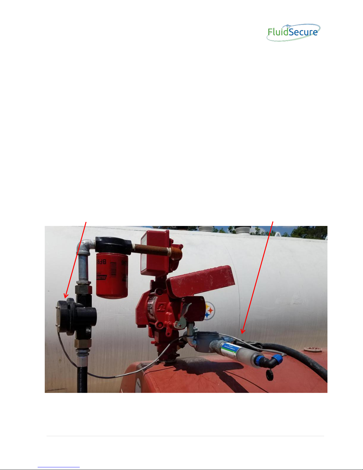
FluidSecure LINK into a typical dispenser/pump. A typical installation for an above
ground tank will look similar to the picture below.
Trak supplied pulser (optional) FluidSecure LINK

4 | P a g e
FluidSecure LINK
Manual Override Switch
Wiring Junction Box
Pulser Cable
Conduit Sealoff

5 | P a g e
2) Wiring Connections
The installation typically involves disconnecting the AC power supply wring (generally
that comes from a nearby building or power source) from the dispenser and re-routing it
through the supplied conduit parts that are supplied as part of the LINK kit and reconnecting the wires to the FluidSecure LINK and dispenser. Under no condition
should a FluidSecure LINK control a pump motor larger than 3/4hp. Larger loads
can be controlled with an external contactor or power relay.
DISPENSER
Solenoid/
Motor
MANUAL
OVERRIDE
SWITCH
FLUIDSECURE LINK
POWER
FROM
BUILDING
or Dispenser
WIRENUTS
BROWN
BROWN
BROWN
BROWN
BLACK
120VAC/
240VAC
BLACK
BLACK
WHITE
WHITE
WHITE
(Neutral)
RED
(+12VDC)
GREEN
(DC Gnd)
ORANGE
GRAY
INTERNAL
PULSER
CONNECTIONS
NOTE:
Two brown wires coming
from the FluidSecure
unit are dry contacts of
a 16 amp mechanical
relay and are not electrically
connected internally in the
FluidSecure Link
FluidSecure Link Wiring Diagram
Alternate power input to run Link from a 12VDC source
External
Link
Pulser
Connector

6 | P a g e
3) Pulser Installation
Two Options:
#1 - Trak Supplied Optional Flow Pulser Use the optional Trak supplied flow
pulser installed between the pump and the hose as seen in prior pictures.. This will
involve removing the hose. This guide shows one of several pulser types that may be
used with the system. Regardless of the configuration, each flow pulser is marked with
an arrow showing the direction of fluid flow. Please note that the optional pulsers are
shipped with pre-installed adapters that convert the 1” straight G type thread into a 1”
NPT female opening. The adapters are O-ring protected into the pulser. Please ensure
that the adapters are secure but do not over tighten.
Warning! Removal of the hose will result in a minor amount of fuel spillage. This
can result in a fire hazard and must be handled with extreme care.
⚫ Power to the dispenser must be turned off before attempting.
⚫ Steps must be taken to recover as much of the fuel contained in the hose for return
back to the tank.
⚫ A fire extinguisher should be available in case of emergency.
⚫ Use non-sparking tools for this operation.
Empty as much fuel from the hose as possible before removing. Hold the end of the
hose high once removed until it can be placed in the recycle container for removal of the
remainder of the fuel. Once the hose is removed, screw the input end of the pulser into
the dispenser using the supplied teflon tape wrapped around the hose nipple adapter.
Note that the pulser has an arrow pointing towards the hose end of the pulser. Next, re-
attach the hose to the output end of the pulser. In general, a 1” hose will screw directly
into the pulser and a 3/4” will require a 1” to 3/4” adapter. Connect the included external
LINK pulser cable to the top of the FluidSecure LINK.
Pulser
PulserAdapter

7 | P a g e
The diagram below shows the wiring connections that are utilized in the external pulser
cable. If using the Trak supplied pulser, the cable is already attached to the pulser and
the installer simply needs to plug the cable into the top of the LINK. If using alternate
third party pulsers, the cable is not terminated at the pulser end. The diagram below
shows the the electrical connections that form the LINK pulser cable. The cable will
have to be connected to the third party pulser by using the appropriate wires suitable for
the pulser.
1 2 3 4 5 6 7
1 2 3 4 5 6 7
SD20TA-ZM Jelen Connector
Male
SD20TA-ZM Jelen Connector
Female
Red
White
Yellow
Black
Brown
Orange
Blue
Pulser Switch
Note: All wires except white, yellow
and black are capped off in pulser
Red
White
Yellow
Black
Brown
WiFi Board
R W B Y BL
Pulser
Security
Red - +3.3
White - Pulser disconnect sense
Yellow - Pulser input
Brown - +5
Black - Ground
10k
+5
+3.3
Pulser Wiring
accessible to user
470
INTERNAL - Not accessible by user

8 | P a g e
#2: Utilizing Exiting Pulsers on Dispensers/Meters Many dispensers and
metering systems come already equipped with pulser units or can be equipped with
third party pulsers. The LINK will interface with most of them. The LINK is equipped
with 2 separate pulser inputs.
a) The first pulser input is a two wire combination that exits from the bottom of the
LINK with all the other wires and is referred to as the LINK internal pulser wires.
Please see wiring diagram on page 5. This input is used when the existing pulser
wires are already internal in the conduit system. These two wires, orange and gray,
are part of an optically isolated circuit. Connecting them together causes the optical
circuit to flash. This in turn will pulse a single pulse each time the wires are
connected. An external pulser will have to connect the two wires for each pulse.The
gray wire is ground and the orange wire is positive.
b) The second alternate pulser input enters into the LINK at the top of the LINK
through the 7-pin circular connector as shown on page 8. This is the same cable
that is supplied with the Trak flow pulser but has no pulser on the end. The wires
can be connected to any pulser output by tying the wires together using wire nuts.
The wiring from the FluidSecure LINK is designed intrinsically safe and can be safely
run without conduit in a Class 1, Division 1 location or any lesser classification. Do
NOT allow it to enter into a junction box, conduit or other device that could connect
these pulser wires to external high voltage wiring.
The black and yellow wires form a pulled up circuit that the external pulser must
connect together to pulse the circuit. External 5VDC is also supplied via the red wire to
power an external pulser circuit.
4) Low Voltage Wiring Connections
The LINK is capable of running from 12 to 24 VDC instead of AC power. The
electrical diagram in A.2. shows a red and green wire labeled as gnd and +12VDC. The
LINK can actually run from 24VDC as well. These two wires can be utilized for power
hookup. The two brown wires also shown are still used to control the power to the
solenoid or pump. Since the brown wires are not electrically connected internally in the
LINK, they can be used with any external control voltage from 5VDC to 240VAC
regardless of the power used to operate the LINK. The same safety warnings apply to
low voltage installation as the high voltage ones.
B. Installation - Standard Dispenser
Wiring connections are the same as the above ground tanks. However, there are
many different dispensers and each one will have differences from one manufacturer to
another. It is not within the scope of this document to address all possible combinations.

9 | P a g e
In general, the FluidSecure LINK should control a solenoid valve, dispenser authorization
signal or a small pump motor. Under no condition should a FluidSecure LINK control
a pump motor larger than 3/4hp. Larger loads can be controlled with an external
contactor or power relay.
1) Conduit Connections between Pump and LINK
Installation for standard dispensers is quite simple. Most have an explosion proof
junction box located in the bottom section of the dispenser. This junction box generally
will have two or more conduits that feed into it. Normally there are additional available
conduit openings in the junction box. Simply unscrew the cap from one of the unused
ports and screw in the FluidSecure LINK. If there are no available openings you will have
to use a rated Class 1, Division 1, T box (or purchase the optional hardware kit) to attach
to the junction box and re-route an existing conduit to the box and then attach the
FluidSecure LINK. The manual override switch can be removed from the wiring
enclosure and inserted into an additional conduit opening in the junction box.
Manual Override Junction Box LINK

10 | P a g e
2) Wiring Connections
Once the LINK is installed, the control wires will be available inside the junction box the LINK
is connected to. The wiring diagram in section A.2 is also applicable here. You can control the
dispenser solenoid valve, dispenser motor, dispenser control signal input or other such device.
The installation typically involves disconnecting the AC power source, making the appropriate
electrical connections and re-connecting the wires to the FluidSecure LINK and dispenser.
Under no condition should a FluidSecure LINK control a pump motor larger than
3/4hp. Larger loads can be controlled with an external contactor or power relay.
3) Pulser Installation
Many dispensers have included pulsers which can be attached to the FluidSecure
LINK. To connect to an existing pulser wire that is located outside the conduit system,
you must utilize the cable and connector that is supplied with the FluidSecure LINK. The
external pulser wiring from the FluidSecure LINK is designed intrinsically safe and can
be safely run without conduit in a Class 1, Division 1 location or any lesser classification.
Do NOT allow it to enter into a junction box, conduit or other device that could connect
these pulser wires to external high voltage wiring
Other pulsers often have their pulser wires within the conduit system and can
connect to the internal LINK pulser wires. Those pulser wires are shown in the drawing
in section A.2 and are labeled orange and gray. The gray wire is ground and the orange
wire is positive DC.
It is not within the scope of this document to cover all possible pulser combinations
that exist on standard dispensers. However, there are generally two common types that
are often used.
1. Reed Switch or microswitch - This is a non- powered switch that opens and closes
for every tenth of a gallon. Some will count more often and others less but a 1/10-gallon
pulse rate is extremely common in the commercial environment. Connect either wire from
this type pulser to the red and green wire in the pulser cable.
2. Open Collector - This is a powered pulser and generally requires 5 to 12 volts to
operate. In general, you will have to determine which of the pulsers wires is ground and
which are the pulse output. Additionally, if the pulser requires external excitation, you
may have to connect a 5 or 12-volt line to the pulser. The FluidSecure LINK produces a
5 VDC output that can be used to power an open collector circuit. The diagram in section
A.2 shows those connections.

11 | P a g e
C. Operating Instructions
Your physical installation should be complete. Power the dispenser on, which in turn
will power the FluidSecure LINK. You will notice a faint blue light in the top half of the
FluidSecure LINK when power is applied. If there is no light, reconfirm that power is
present. If no light is observed, recheck your electrical connections and try again. If no
light is still not observed, refer to the troubleshooting section using the manual.
Calibration of the Pulser vs the Meter:
The FluidSecure pulser must be calibrated unless you know 100% the ratio (example
10:1). The FluidSecure LINK along with the optional purchased pulser or if you are using
an already installed pulser, you must read how many pulses are produced per unit of
measure (gallons, liters, quarts, etc.). We will use the word gallon in this explanation, but
it can be any unit of measure. To calibrate the pulser you must have an authorized cell
phone. In the FluidSecure Information page, in the FluidSecure CLOUD, you will need to
enter in the number of gallons pumped during calibration. The pulses field can be any
initial number. You must contact your FluidSecure administrator to obtain authorization
to run a calibration. Once authorized, you will have to either pump fuel into a calibrated
container or use the existing meter on your dispenser to calibrate. If you have just
installed the pulser (and you probably have at this point) you must pump at least 20 to
30 gallons back into the tank to purge the air out of the pulser and hose. For calibration,
It is best to pump at least 5 gallons for high accuracy but a smaller amount can be utilized.
To begin the calibration, refer to your cell phone user guide for the FluidSecure APP.
Start a transaction and begin pumping into your calibrated container. If you are using
your existing meter, then simply pump the fuel back into the tank or into a vehicle. Stop
at a full gallon mark as close as you can. It doesn’t matter how many gallons you pump
but the more the better. (Please note that we refer to gallons, but the label is unimportant.
You can use quarts, liters or anything else.) When you are finished, the cell phone will
display a count. Call the administrator and report to them total gallons you pumped and
the counts. That is all there is to it.
D. Quick CLOUD Startup Guide
Once installation is complete you will need to enter some data into the FluidSecure
CLOUD webpage. Once the system is shipped, a Company page will be setup
automatically allowing you to start using the software.
The CLOUD-based software must be filled out in proper sequence before any testing
can be performed and transactions at the fuel locations can be started. Any users must

12 | P a g e
be authorized and the FluidSecure LINK must be initialized. These steps will guide you
through the process. Please do them in order so you don’t have to repeat steps.
1. Company Information Page
Enter:
Company Name, Contact Name, Contact Address, Contact Phone Number and
Contact Email. These can be modified or updated later if necessary. Press Save.
2. Select Product Type
Enter in a Product Type (Unleaded, Diesel, etc.).

13 | P a g e
3. Edit Department Information
Enter in Department Number (we suggest you start with 1) and Name. Again, these
can be changed later if necessary.
4. Edit FluidSecure LINK Information
Enter in FluidSecure LINK Name - start with 1
Enter in FluidSecure Current
Name - enter in the serial number
that is on the FluidSecure LINK.
The serial number is all alpha
characters.
Enter in FluidSecure New Name The name you would like for it to
be identified by all users, for
example “Unleaded” – this shows
up as the HOSE name on the APP
Enter in a Tank Number - start
with 1
Enter in the product in the tank
from the drop-down menu
Select Authorized Fueling Times
Select Authorized Fueling Days
Check Disable Geo Location
Enter in a Pump On Time - usually 30
Enter in a Pump Off Time - usually 30
Select Company from drop down menu
Enter Original Name of FluidSecure LINK - this is the serial number entered above

14 | P a g e
Enter Units Measured - enter 10
Enter Units Measured - see Calibration above
Select Time Zone from drop down menu
5. Edit Vehicle Information
Enter Vehicle Number Usually how your
vehicles are identified
Enter Vehicle Name Name of vehicle and
what the transaction
reports show
Enter Department from the drop-down
menu
Select Authorized
FluidSecure LINKS the hoses at which this
vehicle will be allowed
to fuel at
6. Enter Personnel information
No fields are required at
this time. All users are
required to download the
FluidSecure APP to their
phones and register on
their own phone. Once
registered you are
required to go back to
this page to:
Enter in their Access
Level – usually “User”
Department - select
from drop down menu

15 | P a g e
Select Vehicles Allowed to Fuel - these are the vehicles this person is allowed to fuel
Select Authorized Fueling Times - these are the times of the day this person is allowed to
fuel this vehicle
Select Authorized Fueling Sites - these are the sites at which this person is authorized to
fuel at
Active? - click this if this person is allowed to fuel, un-click to de-authorize fueling
permission.
 Loading...