

TRAK TRL 1630HSRX, TRL 1630RX, TRL 1845RX, TRL 2470RX Safety, Installation, Maintenance, Service & Parts List Manual
Page 1

2615 Homestead Place
Rancho Dominguez, CA 90220-5610 USA
T | 310.608.4422 | F | 310.764.2668
Service Department: 800.367.3165
E-mail: [email protected] | [email protected] | web: www.trakmt.com
Document: P/N 29542
Version: 022819
TRAK® TRL LATHES
ProtoTRAK® RLX CNC
Safety, Installation, Maintenance, Service & Parts List
Covers Models:
1630RX
1630HSRX
1845RX
2470RX
Page 2

Copyright 2019, Southwestern Industries, Inc. All rights are reserved. No part of this publication may
be reproduced, stored in a retrieval system, or transmitted, in any form or by any means, mechanical,
photocopying, recording or otherwise, without the prior written permission of Southwestern Industries,
Inc.
While every effort has been made to include all the information required for the purposes of this guide,
Southwestern Industries, Inc. assumes no responsibility for inaccuracies or omission and accepts no
liability for damages resulting from the use of the information contained in this guide.
All brand names and products are trademarks or registered trademarks of their respective holders.
TRAK Machine Tools
Southwestern Industries, Inc.
2615 Homestead Place
Rancho Dominguez, CA 90208-5610
Phn 310.608.4422 Fax 310.764.2668
Service Department
Phn 800.367.3165 Fax 310.886.8029
Page 3

i
Southwestern Industries, Inc.
TRAK TRL Lathe, ProtoTRAK RLX CNC Safety, Installation, Maintenance, Service & Parts List
Table of Contents
1.0 Safety Specifications............................................................................................ 2
1.1 Safety Publications ................................................................................................... 2
1.2 Danger, Warning, Caution, and Note Labels and Notices as Used In This Manual ......... 2
1.3 Safety Precautions .................................................................................................... 5
2.0 Installation .......................................................................................................... 7
2.1 Floor Plan, Layout & Space Requirements .................................................................. 7
2.2 TRAK TRL Lathe Specifications ................................................................................ 10
2.3 Uncrating ............................................................................................................... 11
2.4 Shortages: Inventory Checklist ............................................................................... 12
2.5 Installation Instructions & Checklist ......................................................................... 12
2.6 ProtoTRAK RLX Control Hardware............................................................................ 13
2.7 Lifting and/or Moving the Machine ........................................................................... 14
2.8 Cleaning ................................................................................................................ 14
2.9 Leveling ................................................................................................................. 15
2.10 Electrical Connection .............................................................................................. 16
2.10.1 Phase Converters ............................................................................................ 16
2.11 Air Connection ....................................................................................................... 17
2.12 Mounting the Display Pendant ................................................................................. 17
2.13 Cable Interconnections ........................................................................................... 17
2.14 Machine ID Key ...................................................................................................... 20
2.15 Pendant Maintenance ............................................................................................. 21
2.15.1 How to Clean the Touchscreen ........................................................................ 21
2.16 Lubrication ............................................................................................................. 25
2.16.1 Lube Pump Operation...................................................................................... 25
2.16.2 Factory Default Values .................................................................................. 25
2.16.3 1630RX, 1630 HSRX, 1845RX & 2470RX Headstock Oil Reservoir ....................... 26
2.17 Auxiliary Output ..................................................................................................... 26
2.18 Cutting the Test Part .............................................................................................. 28
2.19 Measurement of the Test Part ................................................................................. 28
2.20 Mounting of an Buck Zero Set Chuck- RX Lathe ........................................................ 29
3.0 Troubleshooting by Symptom ............................................................................ 32
3.1 Problems Related to the Pendant and Computer Module .......................................... 32
3.1.1 Pendant will not Connect to Motion Control in Computer Module at Boot Up ........... 32
3.1.2 Pendant will not Connect to Motion Control in Computer Module ........................... 32
3.1.3 Pendant Does Not Power On ............................................................................... 33
3.1.4 Screen Problems ................................................................................................. 33
3.1.5 RSG Button Does Not Work ................................................................................. 33
3.1.6 System Does Not Respond to Numeric Keys Button Presses .................................. 34
3.1.7 System Does Not Respond to Critical Keys Button Presses ..................................... 34
3.1.8 Door Guards Not Working Properly ...................................................................... 34
3.1.9 Power Reset Button is Not Working ..................................................................... 35
3.1.10 Spindle Does Not Turn ON ............................................................................... 35
3.1.11 Pendant Does not Respond and Appears to be Locked Up ................................. 35
3.1.12 E-Stop Error (Machine Is Disabled)................................................................... 36
3.1.13 Touchscreen Does Not Respond ....................................................................... 36
3.1.14 USB Not working on Pendant ........................................................................... 36
3.1.15 LAN Port Not working on Pendant .................................................................... 37
3.1.16 Axis Fault ....................................................................................................... 37
3.1.17 Will Not Hold Calibration .................................................................................. 37
Page 4

ii
Southwestern Industries, Inc.
TRAK TRL Lathe, ProtoTRAK RLX CNC Safety, Installation, Maintenance, Service & Parts List
3.1.18 Limit Switch Error ........................................................................................... 38
3.2 Problems Relating to Machining Results ................................................................... 39
3.2.1 Poor Finish ......................................................................................................... 39
3.2.2 Turning Diameters Out of Round ......................................................................... 40
3.2.3 Cutting Taper ..................................................................................................... 40
3.2.4 Parts Have Incorrect Dimensions ......................................................................... 40
3.2.5 Threading Problems ............................................................................................ 42
3.3 Problems Regarding the Motion of the Machine ........................................................ 42
3.3.1 Run Away Axis .................................................................................................... 43
3.3.2 Slow Down Axis .................................................................................................. 43
3.3.3 Axis Motor Motion Is Not Smooth......................................................................... 43
3.3.4 Vibration in Motion ............................................................................................. 44
3.4 Problem with the Measurements ............................................................................. 44
3.4.1 X & Z-Axis Measurements Do Not Repeat ............................................................. 45
3.4.2 X & Z-Axis Measurements Are Not Accurate.......................................................... 45
3.4.3 The DRO Is Not Counting .................................................................................... 46
3.4.4 X & Z-Axis DRO Counting in Wrong Direction........................................................ 46
3.4.5 X & Z-Axis Electric Handwheels Count in Wrong Direction ..................................... 46
3.5 Problems with the Machine Tool .............................................................................. 47
3.5.1 Spindle Stalls or Turns-Off During Machining ........................................................ 47
3.5.2 Spindle Motor Hums or Will Not Run .................................................................... 47
3.5.3 Spindle Runs Backwards ..................................................................................... 47
3.5.4 Excess Gearbox Noise ......................................................................................... 48
3.5.5 Headstock is Leaking Oil ..................................................................................... 48
3.5.6 Tailstock Barrel is Stiff......................................................................................... 48
4.0 Diagnostics ........................................................................................................ 49
4.1 The Machine Tool & Set-Up .................................................................................... 49
4.1.1 Leveling ............................................................................................................. 49
4.1.2 A Special Word About the X & Z Gib .................................................................... 49
4.1.3 Lubrication ......................................................................................................... 49
4.1.4 Machining Set-Up ............................................................................................... 49
4.2 The Mechanical Drive Train (X,Z) ............................................................................ 51
4.3 Pendant and Computer Module Diagnostics .............................................................. 52
4.4 Motor Diagnostics ................................................................................................... 54
4.4.1 Cable Connections .............................................................................................. 54
4.5 Servo Drivers ......................................................................................................... 54
4.6 Electrical ................................................................................................................ 56
4.6.1 Checking A/C Voltage .......................................................................................... 57
4.6.2 Checking Fuses ................................................................................................... 57
4.6.3 Main Electrical Box .............................................................................................. 57
4.6.4 Computer Module Connections ............................................................................ 57
4.6.5 Cable Connections .............................................................................................. 59
4.7 Door & Gear .......................................................................................................... 59
4.8 Service Codes ........................................................................................................ 60
4.8.1 Software Codes ................................................................................................. 60
4.8.2 Machine Set-Up Codes ........................................................................................ 61
4.8.3 Diagnostic Codes ................................................................................................ 62
4.8.4 Operator Defaults/Options Codes ......................................................................... 63
5.0 Procedures for Replacements & Maintenance ................................................... 64
5.1 Replacements ........................................................................................................ 64
5.1.1 Brushless Motor Replacement .............................................................................. 64
Page 5

iii
Southwestern Industries, Inc.
TRAK TRL Lathe, ProtoTRAK RLX CNC Safety, Installation, Maintenance, Service & Parts List
5.1.2 Servo Drive Replacement .................................................................................... 64
5.1.3 Pendant and Computer Module Replacement ........................................................ 65
5.1.4 Updating the Pendant and Computer Module Software .......................................... 67
5.1.5 Cable Routing on Machine & In Electrical Cabinet ................................................. 67
5.1.6 Electronic Handwheels & Jogstick ........................................................................ 68
5.1.7 Spindle Drive Belt Replacement ........................................................................... 68
5.1.8 Spindle Encoder Replacement .............................................................................. 69
5.1.9 Spindle Motor Removal ....................................................................................... 69
5.1.10 Aligning Tailstock to Spindle ............................................................................ 70
5.1.11 Spindle Motor Wiring ....................................................................................... 70
5.1.12 Spindle Removal – 1630HSRX only (See Figure 5.1.2) ....................................... 71
5.2 Maintenance .......................................................................................................... 72
5.2.1 Gib Adjustments ................................................................................................ 72
5.2.2 Calibration & Backlash Constants ......................................................................... 74
5.2.3 Lubrication ......................................................................................................... 76
6.0 SWI Turret Options ............................................................................................ 81
6.1 4 & 8 Tool Turret Option ......................................................................................... 81
6.1.1 Field Installation Instructions ............................................................................... 81
6.1.2 Removing the 4 Tool Turret from the Lathe .......................................................... 81
6.1.3 Removing the 8 Tool Turret from a Lathe ............................................................. 82
6.1.4 Troubleshooting the Turret .................................................................................. 84
6.1.5 Turret Maintenance............................................................................................. 85
6.1.6 Warranty Issues ................................................................................................. 85
7.0 Introduction to Self-Service .............................................................................. 86
7.1 When You Have a Service Problem .......................................................................... 86
7.1.1 Communication with the SWI Customer Service Group .......................................... 86
7.2 Replacements ........................................................................................................ 86
7.2.1 Exchange Program .............................................................................................. 86
7.2.2 Return Material Authorization (RMA) Number ....................................................... 86
8.0 Drawings & Parts Lists ....................................................................................... 87
8.1 29531 - DRIVE ASSY - X AXIS - 1630RX .................................................................. 87
8.2 29533 - DRIVE ASSY - X AXIS - 1845RX .................................................................. 87
8.3 29535 - DRIVE ASSY - X AXIS - 2470RX .................................................................. 87
8.4 29532 - DRIVE ASSY - Z AXIS - 1630RX................................................................... 87
8.5 29534 - DRIVE ASSY - Z AXIS - 1845RX................................................................... 87
8.6 29536 - DRIVE ASSY - Z AXIS - 2470RX................................................................... 87
List of Figures
Figure 2.1a – 1630RX and 1630HSRX Lathe .............................................................................. 7
Figure 2.1b – 1845RX Lathe .................................................................................................... 8
Figure 2.1c – 2470RX Lathe ..................................................................................................... 9
Figure 2.3 – 2470 Door Shipping Bracket ................................................................................ 11
Figure 2.7 – Lifting and/or Moving the Machine ...................................................................... 14
Figure 2.9 - TRAK TRL Lathes – Leveling ................................................................................ 15
Figure 2.10 - Wiring the TRAK TRL Lathe ............................................................................... 17
Figure 2.13a - RLX - Pendant Front Side - P/N 29008-2 ........................................................... 18
Figure 2.13b - RLX - Pendant Back Side - P/N 29008-2 ............................................................ 19
Figure 2.13c - RLX - Pendant Cable Connections ..................................................................... 20
Figure 2.14 - RLX – Machine ID Key ....................................................................................... 20
Figure 2.15.1 - RLX – Electrical Cabinet Connectivity ............................................................... 22
Figure 2.15.2 - RLX – Computer Module Connectivity .............................................................. 24
Page 6

iv
Southwestern Industries, Inc.
TRAK TRL Lathe, ProtoTRAK RLX CNC Safety, Installation, Maintenance, Service & Parts List
Figure 2.17a – Auxiliary Output Connectivity ........................................................................... 26
Figure 2.17b – Auxiliary Output Example of Air Blast ............................................................... 27
Figure 2.19 - All TRAK TRL Lathes - Test Part ......................................................................... 28
Figure 4.5a Motor Servo Driver Fault Errors ............................................................................ 55
Figure 4.5b Motor Servo Driver Fault Errors ............................................................................ 56
Figure 5.1.2 - Servo Drive and Motor Replacement & Part List ................................................. 65
Figure 5.1.3.2 - Pendant & Computer Module Replacement ..................................................... 66
Figure 5.1.3.2 - Pendant & Computer Module Replacement ..................................................... 67
Figure 5.1.6 - Electronic Handwheels & Jogstick ...................................................................... 68
Figure 5.1.8 – 1630RX, 1630HSRX, 1845RX, & 2470RX - Spindle Motor Belt Adjustment ........... 69
Figure 5.1.10 - All RX Lathes - Tailstock Adjustment ................................................................ 70
Figure 5.1.12a - 1630HSRX – Spindle Assy P/N 24785 & Parts List Shown ................................ 71
Figure 5.1.12b - 1630HSRX – Spindle Assy P/N 24785 & Parts List Shown ................................ 72
Figure 5.2.1.1 - All RX Lathes - X Axis Gib .............................................................................. 73
Figure 5.2.1.2 - All RX Lathes - Z Axis Gib............................................................................... 74
Figure 5.2.2.1 - All RX Lathes - Calibration Set-Up ................................................................... 75
Figure 5.2.3.1a - Headstock Oil Removal ................................................................................ 77
Figure 5.2.3.1b - 1630RX & 1630HSRX – System Lubrication – P/N 24786 & Parts List .............. 78
Figure 5.2.3.2 - All RX Lathes - Tailstock Lubrication ............................................................... 79
Page 7
1
TRAK Machine Tools
Southwestern Industries, Inc.
TRAK TRL Lathe, ProtoTRAK RLX CNC Safety, Installation, Maintenance, Service & Parts List
TRAK Machine Tools Reference Page
Login:
Password:
Use this page to log your machine’s Model and Serial Number, as well as your Login
credentials for buytrakparts.com. For additional manuals visit www.trakmt.com. For
additional machine drawings not found in this manual, visit www.buytrakparts.com.
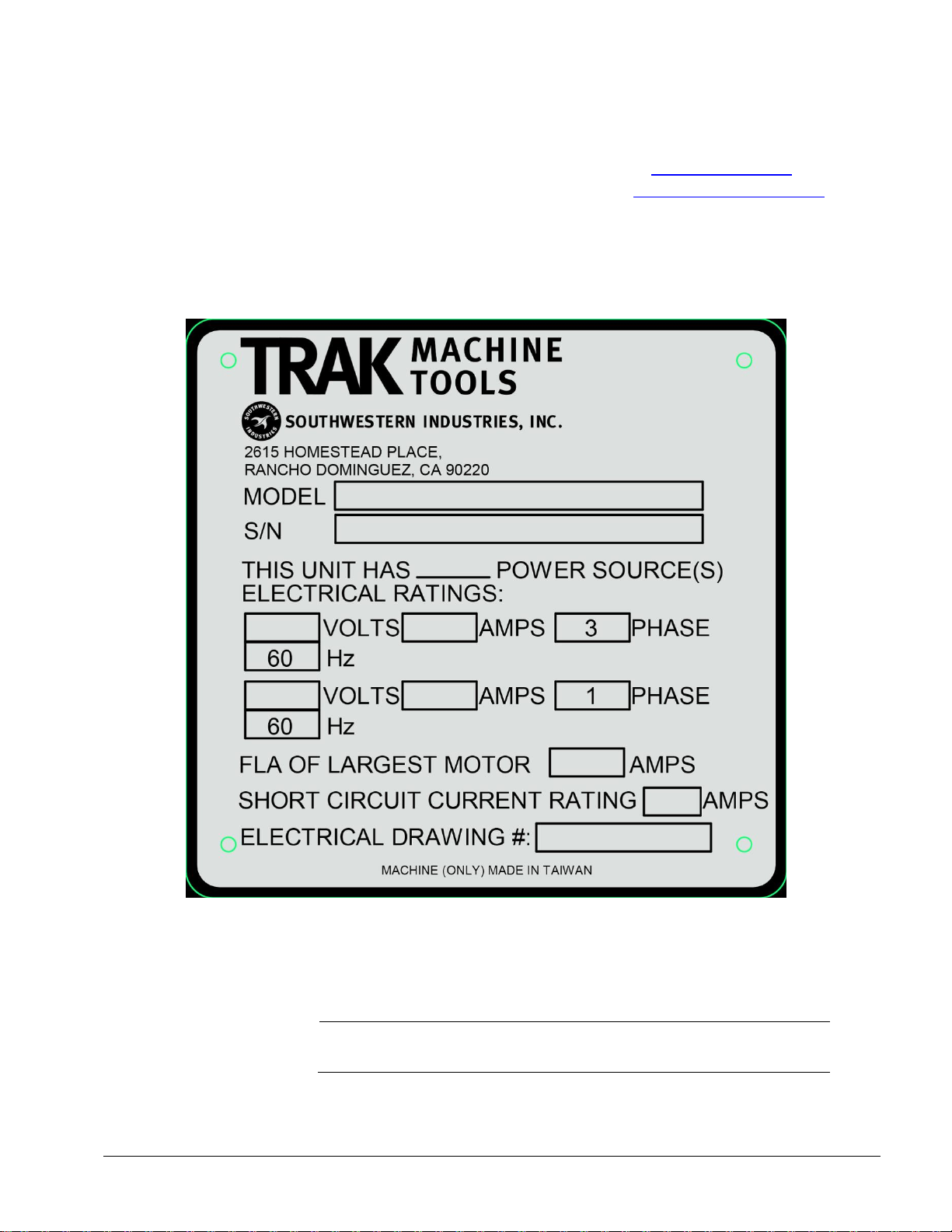
Machine Model & Serial Number
The plate below is for you to write down your model and serial number. Keep this info
handy for when you contact Customer Service.
Buytrakparts.com Login Credentials
Page 8

2
TRAK Machine Tools
Southwestern Industries, Inc.
TRAK TRL Lathe, ProtoTRAK RLX CNC Safety, Installation, Maintenance, Service & Parts List
1.0 Safety Specifications
The safe operation of the TRAK TRL Lathe & ProtoTRAK RLX CNC depends on its proper use and the
precautions taken by each operator.
Read and study the TRAK TRL Lathe & ProtoTRAK RLX CNC Safety, Programming, Operating, and
Care Manual. Be certain that every operator understands the operation and safety requirements of
this machine
Read and study the TRAK TRL Lathe Safety, Installation, Maintenance, Service & Parts List Manual.
Be certain that every operator understands the operation and safety requirements of this machine
before
Always wear safety glasses and safety shoes.
Always stop the spindle and check to ensure the CNC control is in the stop mode before changing or
adjusting the tool or workpiece.
Never wear gloves, rings, watches, long sleeves, neckties, jewelry, or other loose items when
operating, or around the machine.
Use adequate point of operation safeguarding. It is the responsibility of the employer to provide
and ensure point of operation safeguarding per ANSI B11.6-2001.
1.1 Safety Publications
Refer to and study the following publications for assistance in enhancing the safe use of this machine:
Safety Requirements for Manual Turning Machines with or without Automatic Control (ANSI
B11.6-2001). Available from the American National Standards Institute, 1819 L Street N. W.,
Washington, D.C. 20036.
before
servicing.
its use.
Concepts And Techniques Of Machine Safeguarding (OSHA Publication Number 3067).
Available from The Publication Office - O.S.H.A., U.S. Department of Labor, 200 Constitution
Avenue, NW, Washington, DC 20210.
All other regulations are specific to the State in which the machine is installed.
1.2 Danger, Warning, Caution, and Note Labels and Notices as Used In This
Manual
DANGER - Immediate hazards that
the machine are red in color.
WARNING - Hazards or unsafe practices that
to the equipment. Warning labels on the machine are gold in color.
CAUTION - Hazards or unsafe practices that
equipment/product damage. Caution labels on the machine are gold in color.
NOTE - Call attention to specific issues requiring special attention or understanding.
will
result in severe personal injury or death. Danger labels on
could
result in severe personal injury and/or damage
could
result in minor personal injury or
Page 9
3
TRAK Machine Tools
Southwestern Industries, Inc.
TRAK TRL Lathe, ProtoTRAK RLX CNC Safety, Installation, Maintenance, Service & Parts List
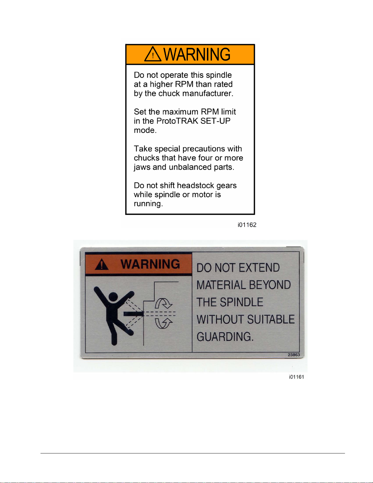
Safety & Information Labels Used On The
TRAK TRL Lathe
It is forbidden by OSHA regulations and by law to deface, destroy or remove any of these
labels
Page 10
4
TRAK Machine Tools
Southwestern Industries, Inc.
TRAK TRL Lathe, ProtoTRAK RLX CNC Safety, Installation, Maintenance, Service & Parts List
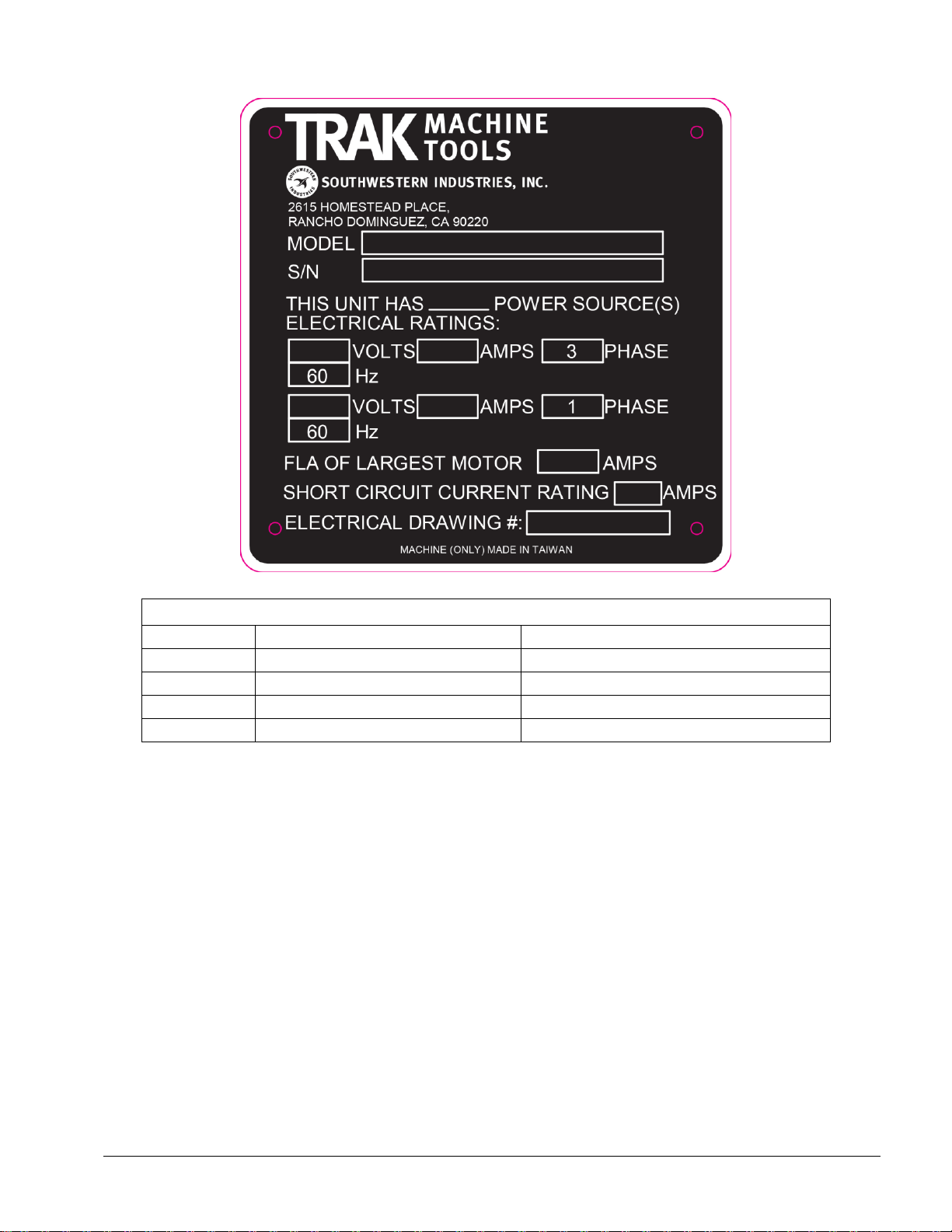
Power Requirements at 208 Volts, 3-phase 60 Hz
Model
Full-load Amp of Machine
Full-load Amp of Largest Motor
1630RX
44
20
1630HSRX
44
20
1845RX
54
30
2470RX
75
40.5
Page 11

5
TRAK Machine Tools
Southwestern Industries, Inc.
TRAK TRL Lathe, ProtoTRAK RLX CNC Safety, Installation, Maintenance, Service & Parts List
1.3 Safety Precautions
WARNING!
Use only chucks which are rated to the maximum RPM of the lathe.
1. Do not operate this machine before the TRAK TRL Lathe and ProtoTRAK RLX CNC Programming,
Operating and Care Manual has been studied and understood.
2. Read and study this TRAK TRL Lathe Safety, Installation, Maintenance, Service & Parts List Manual. Be
certain that every operator understands the operation and safety requirements of this machine
servicing.
3. Do not run this machine without knowing the function of every control key, button, knob, or handle.
Ask your supervisor or a qualified instructor for help when needed.
4. Protect your eyes. Wear approved safety glasses (with side shields) at all times.
5. Don't get caught in moving parts. Before operating this machine, remove all jewelry, including watches
and rings, neckties, and any loose-fitting clothing.
6. Keep your hair away from moving parts. Wear adequate safety headgear.
7. Protect your feet. Wear safety shoes with oil-resistant, anti-skid soles, and steel toes.
8. Take off gloves before you start the machine. Gloves are easily caught in moving parts.
9. Remove all tools (wrenches, chuck keys, etc.) from the machine before you start. Loose items can
become dangerous flying projectiles.
before
10. Never operate any machine tool after consuming alcoholic beverages, or taking strong medications, or
while using non-prescription drugs.
11. Protect your hands. Stop the machine spindle and ensure that the CNC control is in the STOP mode:
Before changing tools
Before changing parts
Before you clear away the chips, oil or coolant. Always use a chip scraper or brush
Before you make an adjustment to the part, chuck, coolant nozzle or take measurements
Before you open safeguards (protective shields, etc.). Never reach for the part, tool, or fixture
around a safeguard.
12. Protect your eyes and the machine as well. Don't use a compressed air hose to remove the chips or
clean the machine (oil, coolant, etc.).
13. Stop and disconnect the power to the machine before you change belts, pulley, gears, etc.
14. Keep work area well lighted. Ask for additional light if needed.
15. Do not lean on the machine while it is running.
16. Prevent slippage. Keep the work area dry and clean. Remove the chips, oil, coolant and obstacles of
any kind around the machine.
17. Avoid getting pinched in places where the spindle, carriage, cross slide or sliding door create "pinch
points" while in motion.
18. Securely clamp and properly locate the workpiece in the chuck or in the fixture. Use proper tool holding
equipment.
19. Use correct cutting parameters (speed, feed, and depth of cut) in order to prevent tool breakage.
Page 12

6
TRAK Machine Tools
Southwestern Industries, Inc.
TRAK TRL Lathe, ProtoTRAK RLX CNC Safety, Installation, Maintenance, Service & Parts List
20. Use proper cutting tools for the job.
21. Prevent damage to the workpiece or the cutting tool. Never start the machine (including the rotation of
the spindle) if the tool is in contact with the part.
22. Don't use dull or damaged cutting tools. They break easily and may become airborne. Inspect the
sharpness of the edges, and the integrity of cutting tools and their holders.
23. Large overhangs on cutting tools when not required result in accidents and damaged parts.
24. Prevent fires. When machining certain materials (magnesium, etc.) the chips and dust are highly
flammable. Obtain special instruction from your supervisor before machining these materials.
25. Prevent fires. Keep flammable materials and fluids away from the machine and hot, flying chips.
26. Never change gears when the spindle is rotating.
27. Do not rotate the spindle by hand unless the Red Emergency Stop button is pressed.
Page 13
7
TRAK Machine Tools
Southwestern Industries, Inc.
TRAK TRL Lathe, ProtoTRAK RLX CNC Safety, Installation, Maintenance, Service & Parts List
2.0 Installation
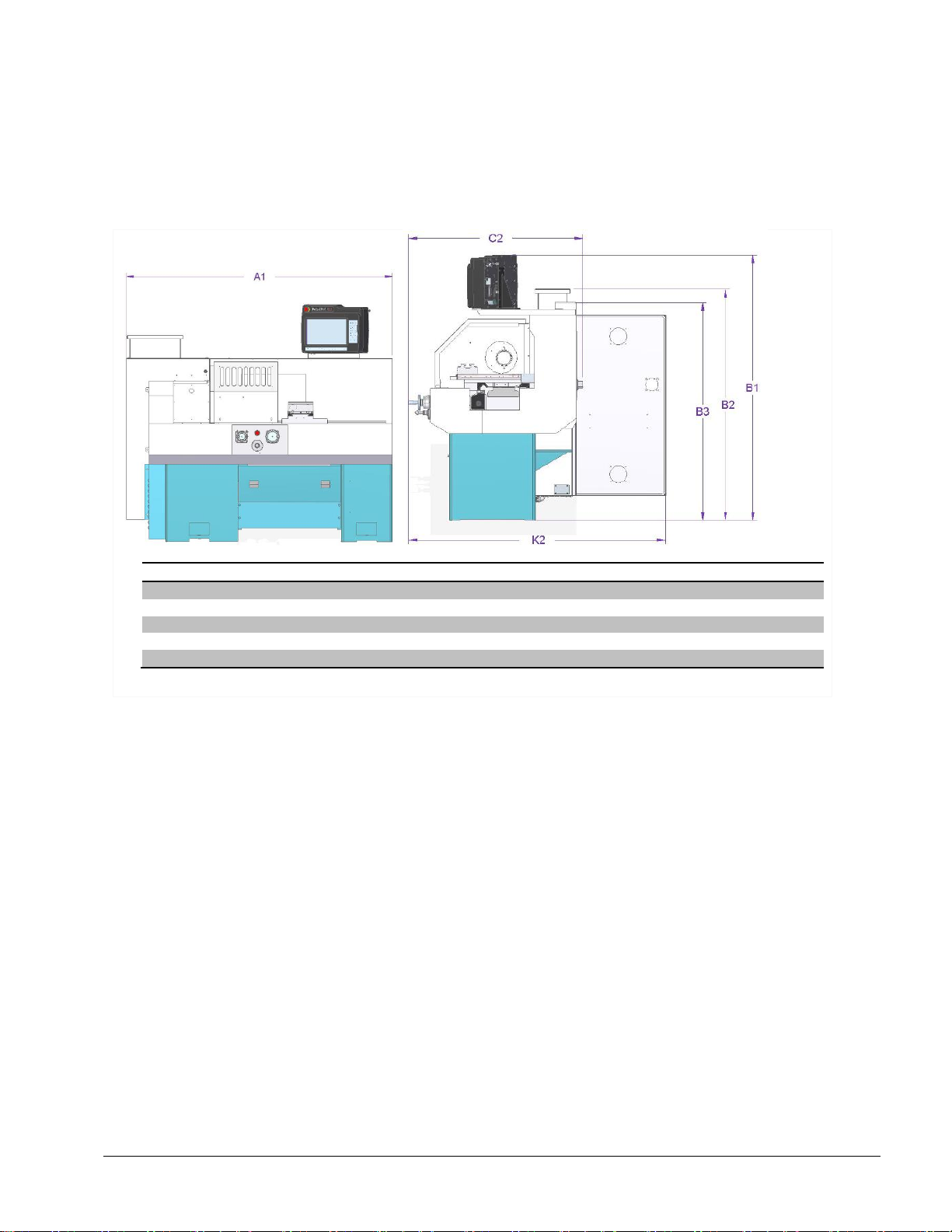
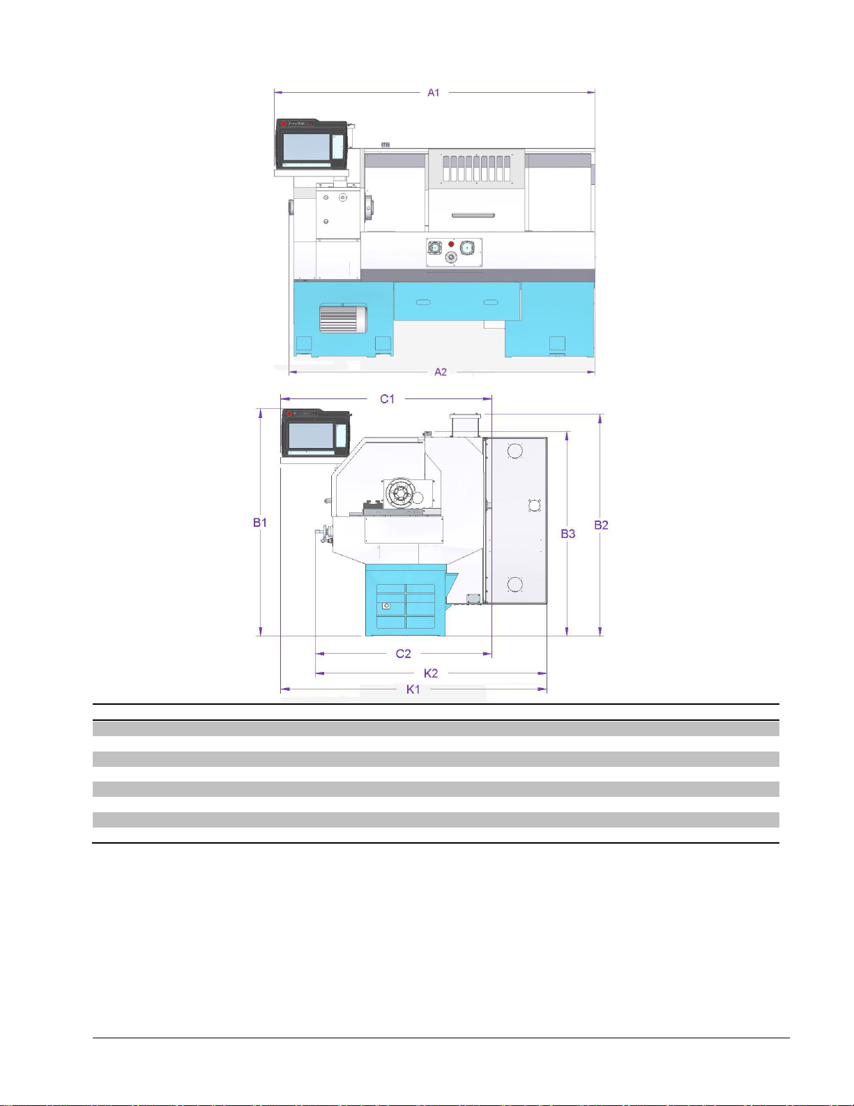
A1
Overall Width
81.9375”
B1
Height of Machine Base to Top of Pendant
72.375”
B2
Height of Machine Base to Top of Electrical Cabinet
63”
B3
Height of Machine Base to Top of Machine
59.375”
C2
Depth of Machine (door closed)
45.3125”
K2
Depth of Machine (door open)
69.875”
Read and understand this entire installation section before beginning the installation procedure.
2.1 Floor Plan, Layout & Space Requirements
Figure 2.1a – 1630RX and 1630HSRX Lathe
Page 14
8
TRAK Machine Tools
Southwestern Industries, Inc.
TRAK TRL Lathe, ProtoTRAK RLX CNC Safety, Installation, Maintenance, Service & Parts List
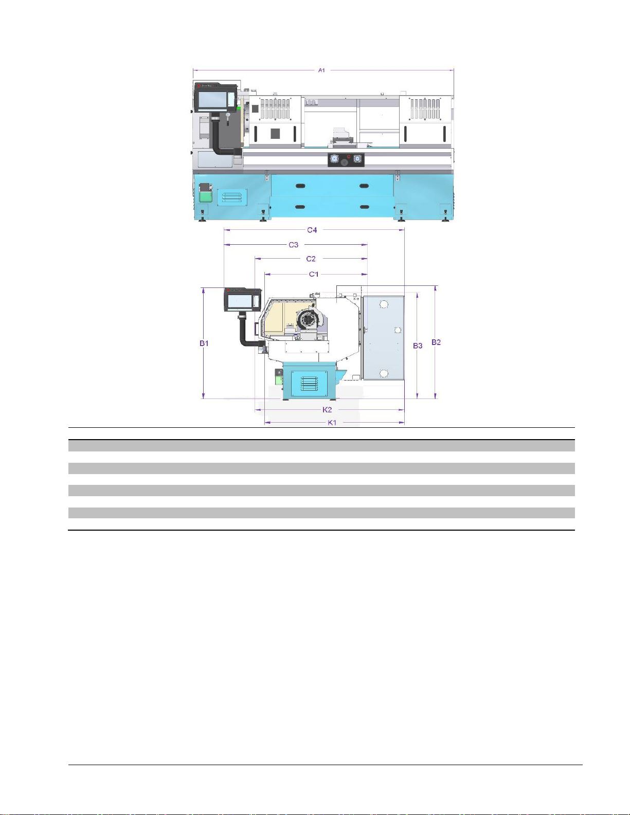
A1
Overall Width
94.25”
A2
Maximum Width of Machine (Pendant arm retracted)
89.9375”
B1
Height of Machine Base to Top of Pendant
69.9375”
B2
Height of Machine Base to Top of Electrical Cabinet
68.25”
B3
Height of Machine Base to Top of Machine
63.25”
C1
Depth of Machine with Pendant swung out (door closed)
65.375”
C2
Depth of Machine Pendant retracted (door closed)
55.125”
K1
Depth of Machine with Pendant swung out (door open)
88.3125”
K2
Depth of Machine with Pendant retracted (door open)
71.75”
Figure 2.1b – 1845RX Lathe
Page 15
9
TRAK Machine Tools
Southwestern Industries, Inc.
TRAK TRL Lathe, ProtoTRAK RLX CNC Safety, Installation, Maintenance, Service & Parts List
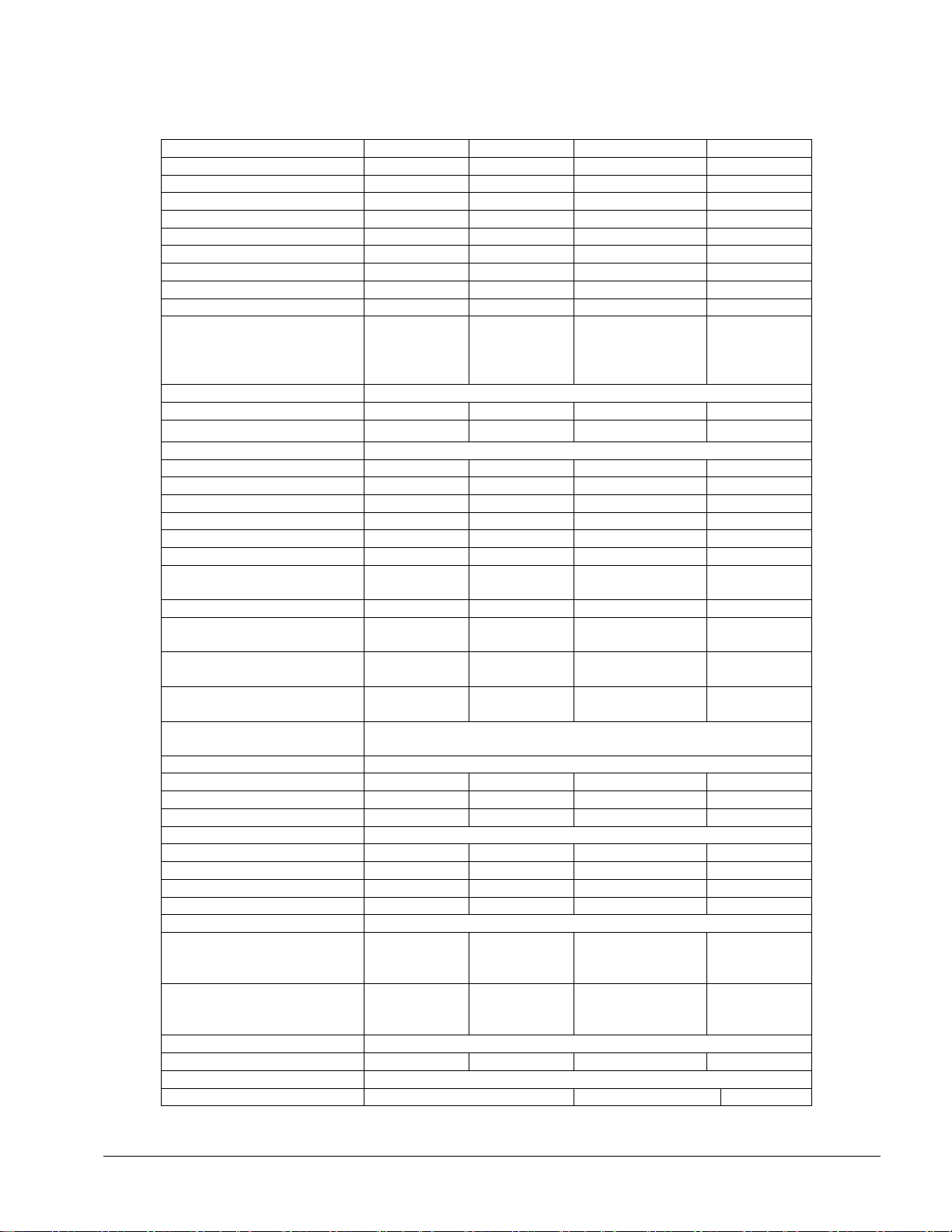
A1
Overall Width
129.125”
A2
Maximum Width of Machine (Pendant arm retracted)
89.9375”
B1
Height of Machine Base to Top of Pendant
69.9375”
B2
Height of Machine Base to Top of Machine
68.25”
B3
Depth of Machine with Pendant swung out (door closed)
82”
C1
Depth of Machine with Pendant retracted (door closed)
64.75”
C2
Depth of Machine with Pendant retracted (door closed)
55.125”
K1
Depth of Machine with Pendant swung out (door open)
88.3125”
K2
Depth of Machine with Pendant retracted (door open)
85.0625”
Figure 2.1c – 2470RX Lathe
Page 16
10
TRAK Machine Tools
Southwestern Industries, Inc.
TRAK TRL Lathe, ProtoTRAK RLX CNC Safety, Installation, Maintenance, Service & Parts List
2.2 TRAK TRL Lathe Specifications
Capacity
1630RX
1630HSRX
1845RX
2470RX
Height of Centers
8”
8”
9”
12”
Distance Between Centers
30”
30”
45”
70”
Swing Over Bed
16”
16”
18.1”
24”
Swing Over Saddle Wings
16”
16”
17”
24”
Swing Over Cross Slide
8.6”
8.6”
9.13”
14.5”
Cross Slide Travel
8.5”
8.5”
10.6”
12.5”
Tool Section Max.
¾”
¾”
1”
1”
Coolant
8 gal.
8 gal.
13 gal.
15 gal.
Oil Pump – Way Lubrication
2 liter
2 liter
2 liter
2 liter
Oil Reservoir – Headstock
1.5 gal.
None
1.85 gal.
5.3 gal
~6.3 gallon
with oil cooler
option
Bed
Width
12.6”
12.6”
13.4”
14.57”
Height
12.6”
12.6”
12.4”
15”
Headstock
Spindle Nose
D1-6
A2-4
D1-6
D1-8
Spindle Through Hole
2.12”
1.57”
2.36”
4.09”
Spindle Taper
MT#6
MT#5
MT #6
MT #8
Taper in Reduction Sleeve
n/a
n/a
MT #4
MT #5
Spindle Taper Runout
Max 0.0004”
Max 0.0003”
Max 0.0004”
Max 0.0004”
Spindle Face Runout
Max 0.0006”
Max 0.0006”
Max 0.0006”
Max 0.0006”
Spindle Diameter Front
Bearing
3.15”
2.56”
3.35”
5.51”
Number of Bearings
2 5 2
2
Number of Spindle Speed
Ranges
1 1 2
2
Spindle Speed Range (RPM)
150-2500
150-4000
80 – 850
250 - 2500
40-670, 100-
1800
Spindle ID Thread on end of
Spindle
M56 X 2 MM
Pitch
M56 X 2 MM
Pitch
N/A
N/A
Headstock and Tailstock
Alignment (Top of Arbor)
Up and Down tolerance 0.000”
+ 0.004” only at tailstock end
Tailstock
Quill Travel
5.75”
5.75”
6”
8.5”
Quill Diameter
2.36”
2.36”
2.56”
3.5”
Quill Taper Hole
MT#4
MT#4
MT#4
MT #5
Spindle Motor
H.P.
7.5
7.5
10
15
Voltage
200 to 240
200 to 240
200 to 240
200 to 240
Amps, Full Load
44
44
54
75
Phase, Hz
3/60
3/60
3/60
3/60
Dimensions
Net Inches L x W x H lbs.
82 x 40 x 71”,
2750
82 x 40 x 71”,
2750
88.5 x 49 x 61”,
3285
129 x 60 x
77”
6500 lbs
Ship Inches L x W x H lbs.
87 x 45 x 67”,
3420
87 x 45 x 67”,
3420
91 x 52 x84
3800 lbs
134 x 64 x
77”
6900 lbs
Other
Coolant Pump Motor, H.P.
1/8
1/8
1/8
1/8
Spindle Motor Brake
Dynamic Braking
Way Surface Hardness
400 – 450 HB
480-560 HB
480-560 HB
Page 17
11
TRAK Machine Tools
Southwestern Industries, Inc.
TRAK TRL Lathe, ProtoTRAK RLX CNC Safety, Installation, Maintenance, Service & Parts List
Headstock Lubrication
Oil Bath
Grease
Oil Bath
Oil Bath
Options
Tooling Kit
¾”
¾”
¾” or 1”
1”
Chuck
8”, D1-6
6”, A2-4
8”, D1-6
12”, D1-8
5C Collet Closer
D1-6
A2-4
D1-6
n/a
Turret Option
¾”, 8-
Position
¾”, 4-
position
¾”, 8-
Position
¾”, 4-
position
¾ or 1” 8-position
¾ or 1” 4-position
1”, 4-
position
1”, 8-
position
Gang Tooling
n/a
n/a
¾”
n/a
* no maintenance grease cartridge
ATTENTION!
Immediately report, in writing, any damages observed at this time that can be
attributed to the transportation or improper handling/moving of the machine.
2.3 Uncrating
Carefully remove the wood crate and protective packaging, paying attention not to scratch, damage, or mar
any parts of the machine.
Remove the cardboard boxes with the PENDANT DISPLAY (handle carefully). The leveling pads and screws
for the machine can be found in the toolbox.
Loosen and remove the screws and nuts holding the machine to the wood pallet.
Figure 2.3 shows the bracket used to ship the 2470 doors during shipment. This bracket remains on the
machine, but the bolt circled is to be removed.
Figure 2.3 – 2470 Door Shipping Bracket
Page 18

12
TRAK Machine Tools
Southwestern Industries, Inc.
TRAK TRL Lathe, ProtoTRAK RLX CNC Safety, Installation, Maintenance, Service & Parts List
2.4 Shortages: Inventory Checklist
1.
Shut off power to the machine.
2.
Visually inspect the 208-wiring going into the electrical panel. Visually verify the wiring is correct
per our wiring diagram. Make sure a strain relief is being used where the wiring enters the
cabinet. Have the customer repair any wiring discrepancies.
3.
Clean the machine if needed and remove any remaining grease.
4.
Mount the pendant on top of the sliding door or on the pendant arm. Make sure the pendant
swivels and slides easily.
5.
Make and check all the proper electrical connections from the pendant to the electrical cabinet.
See the pendant and electrical cabinet wiring diagrams. Be sure to mount the cable cover to the
left side of the pendant.
6.
Slide the door or doors back and forth to make sure it slides smoothly. For the 2470, remove the
bolt that holds the door in place during shipment. There is one for each door. See picture in
section 2.3. For the 1845, remove the bracket that holds the door in place.
7.
Remove the protective plastic cover from the headstock nameplate.
8.
Turn on the power to the machine and to the pendant. Ensure that the 208V line is plugged in.
9.
Check that oil is flowing to the headstock when the spindle is on. For the 2470 oil cooler option,
make sure the pump is rotating the correct direction (CCW as indicated by arrow on pump).
Failure to do so will not allow the oil cooler to work.
10.
Lubricate all the way surfaces and the ball screws. Under service codes press code 300 to
operate the lube pump.
11.
Jog the saddle and cross slide back and forth until the way surfaces are well lubricated. Oil
should be visible on all the way surfaces.
12.
Position the saddle and tailstock to the center of the bed for leveling.
13.
Check the level of the machine. The machine should be level to within 0.0008" longitudinally and
0.0005" transversely. Make any necessary adjustments.
14.
Check the tailstock and the tailstock barrel locks by locking and unlocking. Run the tailstock
barrel in and out to ensure proper function.
15.
For the 1845RX and 2470RX, shift the headstock in low and high gear. Verify that the control
recognizes each gear. To run the spindle, a maximum RPM must be set in SETUP mode.
16.
Open and close the door and verify the door switch is functional. The control should display a
message of “DOOR OPEN” in DRO mode when the door is open and it should disappear when the
door is closed.
17.
Make sure the X and Z electronic handwheels and jogstick are functional.
18.
Check to make sure that both E-Stop buttons are functioning correctly.
19.
Perform Service Code 123 to calibrate the X and Z-axis using a 150mm standard.
______Machine (check model and serial number)
______ Leveling pads and screws (4 each for 1630RX, and 1630HSRX, 8 each for 2470RX, and 6
each for 1845 RX)
______ Pendant Display – 29006-3
______ Toolbox with various tools
______ TRAK Lathe Safety, Operation & Programming Manual (P/N 29540)
______ TRAK Lathe Safety, Installation, Maintenance, Service & Parts List Manual (P/N 29542)
In case of shortages, contact the representative from whom you purchased the machine.
2.5 Installation Instructions & Checklist
Installer: Use this checklist to assure a complete set-up of the RX Lathes.
Page 19
13
TRAK Machine Tools
Southwestern Industries, Inc.
TRAK TRL Lathe, ProtoTRAK RLX CNC Safety, Installation, Maintenance, Service & Parts List
20.
Perform Service Code 127 and 128 to manually calculate the backlash for the X and Z-axis.
21.
Check for positional accuracy and repeatability on the X and Z-axis using programs X LATHE
REPEAT.PT10 and Z LATHE REPEAT.PT10 respectively. Positioning and repeatability values
should be less than or = to 0.0005”. Programs can be found on hard drive under the PT4 folder
followed by the SWI TEST PROGRAMS folder. Note: the door must be closed to run these
programs.
22.
Run the spindle throughout each gear range at various speeds.
23.
Use the accessory key on the pendant. Make sure the coolant pump turns on. The accessory
key should be in the ON position in DRO to test.
24.
Check to make sure the limit switches are functioning properly where applicable.
25.
Cut the test part to check for taper. Measure the test bar and make any machine adjustments.
If unacceptable taper is found, re-check the level before attempting to adjust the headstock.
26.
Attach Lathe Maintenance Schedule Sticker on machine.
27.
Wipe down the machine to finish.
CAUTION!
If the TRAK Lathe has a chuck mounted to the spindle, make sure the chuck is mounted properly
to the spindle and also make sure the chuck jaws are engaged onto themselves or a piece of
material before running the machine.
If the chuck was not purchased from SWI, check to make sure the chuck is rated for the
maximum rpm of the machine. If it is not, do not run the machine above the chuck’s maximum
rated rpm.
If the chuck’s rpm rate is unknown, do not run the chuck over 1000 rpm.
The chucks purchased from SWI are rated for the machine's maximum rpm.
2.6 ProtoTRAK RLX Control Hardware
2-axis CNC, 2-axis DRO
Intel® 2 GHz or faster PC-based processor or faster
4 GB of RAM or higher
32 GB or larger mSATA SSD (solid state) memory drive
15.6” color LCD for clear presentation of prompts, status information and part graphics
Touch screen activated graphical menus with context configured touch keys
LED status lights built into run panel
4 USB ports (plus 1 for the options key as a USB drive)
2 Ethernet Ports (1 for the control system and 1 for the user)
Polycarbonate sealed membrane and gasket sealed control enclosure to lock out contamination
Feedrate override of programmed feedrate and rapid
Spindle Control (FWD, REV, OFF) keys
Accessory button to control coolant and AUTO mode in RUN mode
Programmable Spindle Speed
Feed STOP and GO keys
Speed override of programmed spindle speed
Power Reset Button
Modular design simplifies service and maximizes uptime
Limit switches for the X and Z-axes that are installed to prevent crashes. Optional on some lathes.
Electronic handwheels on the X and Z-axes.
Fine vs Course EHW resolution control
Jogstick for convenient jog
D.C. Servo Motors rated at 335 in-oz continuous torque for X axis and 900 in-oz for the Z-axis
Page 20
14
TRAK Machine Tools
Southwestern Industries, Inc.
TRAK TRL Lathe, ProtoTRAK RLX CNC Safety, Installation, Maintenance, Service & Parts List
Precision ground ballscrews in the carriage and cross slide to ensure smooth accurate contours
CAUTION!
Proper equipment of sufficient capacity must be used when lifting and/or moving the
machine.
Lathe Model
Machine
Weight
Approximate Machine
Shipping Weight
Minimum Forklift
Capacity
1630RX
2,875 Lbs
3,420 Lbs
6,000 Lbs
1630HSRX
2,875 Lbs
3,420 Lbs
6,000 Lbs
1845RX
3,285 Lbs
3,800 Lbs
8,000 Lbs
2470RX
6,500 Lbs
6,900 Lbs
10,000 Lbs
WARNING!
Do not use gasoline or other flammable cleaning agents for cleaning the machine.
without backlash
2.7 Lifting and/or Moving the Machine
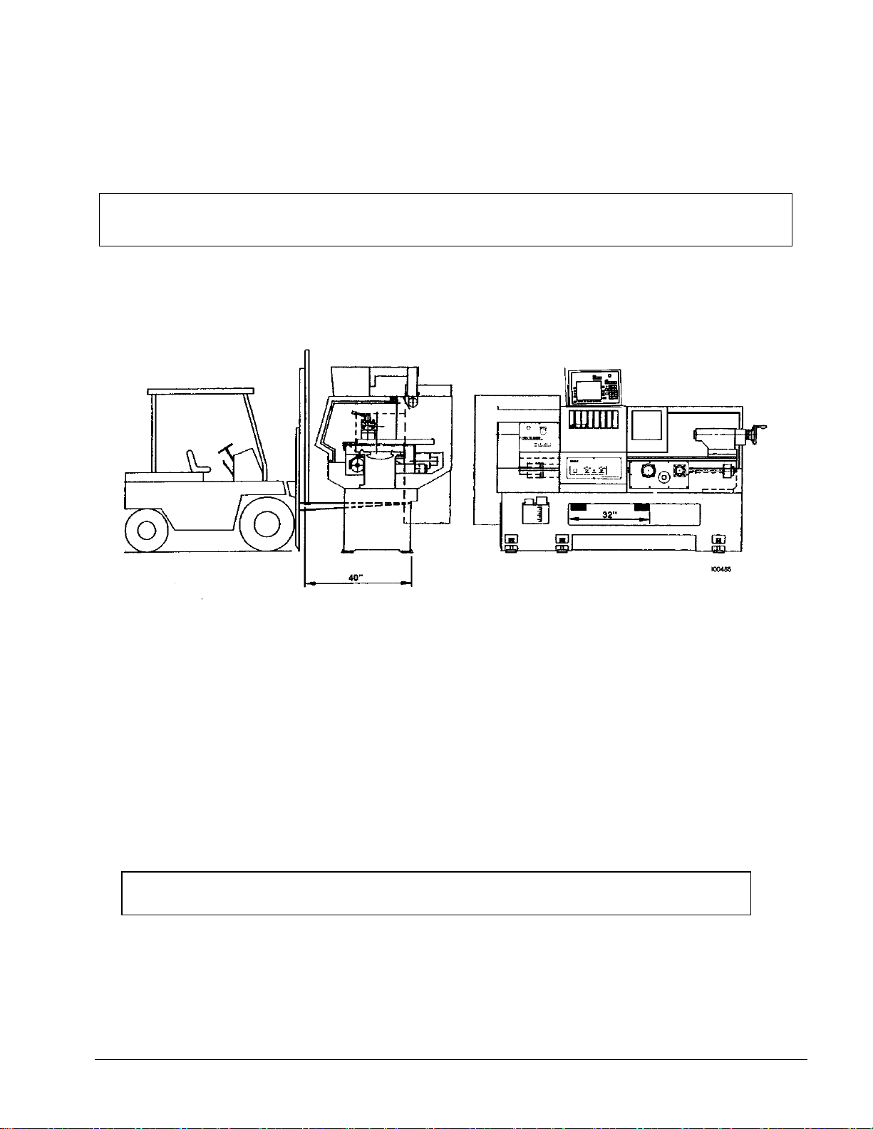
To lift the machine, remove the chip pan. Place the forks of the forklift at least 32” apart as shown in the
figure below. Be certain to lift the lathe toward the headstock.
Figure 5 - Lifting the Lathe
Do not attempt to lift this machine with a forklift having less than 6000 lb capacity for the 1630,
8000 lb capacity for the 1845 and 10000 lb capacity for the 2470.
Do not remove the skid from the machine until it is brought to its final position, especially if the
machine is to be moved on rollers.
Figure 2.7 – Lifting and/or Moving the Machine
Once the skid has been removed, place the machine in position on top of the four (4) for the 1630RX, six (6)
for the 1845RX and eight (8) rest pads for the 2470RX.
For proper operation, the machine should be set on a substantial floor capable of supporting the weight
safely. For the location of the bolt holes, size and recommended mounting, see Figures 2.1a through 2.1c.
2.8 Cleaning
1. Remove rust protective coating from the machine before moving any slideways.
2. The coating is best removed with clean, dry rags. Do not use a cleaning solution that may
damage the rubber way scrapers, plastic parts, or paint.
3. It may be necessary to move the carriage and cross slide back and forward as well as left
and right.
Page 21
15
TRAK Machine Tools
Southwestern Industries, Inc.
TRAK TRL Lathe, ProtoTRAK RLX CNC Safety, Installation, Maintenance, Service & Parts List
CAUTION!
Never move any of the above parts over ways that were not previously cleaned.
Serious damage to the TURCITE surface of slideways can occur.
I00193
4. Be certain the carriage, cross slide and spindle move freely and smoothly over their entire
length.
2.9 Leveling
The precision and durability of the lathe depends on it being leveled properly. Final inspection can be done
only when the machine has been correctly leveled.
After the machine is in position on top of the 4/6/8 rest pads, it must be leveled by the use of the 4/6/8
leveling bolts. It is important that the lathe be level in order to produce accurate work. It may be
necessary to lag bolt the machine in order to eliminate a small amount of twist.
NOTE: The use of a precision level having a minimum accuracy of .0005" over 10.0" will be required.
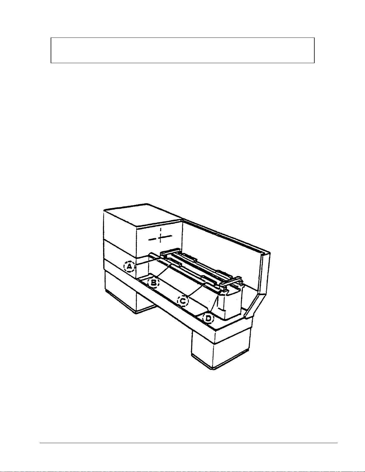
Move the saddle and tailstock to the center of the bed. To take a reading off the level longitudinally, place
the level at each of the four (4) corners of the bedways (Figure 2.9, Positions B & C). To take a reading off
the level transversely, place it on top of .7500" parallels at each end of the bedways (Figure 2.9 Positions A
& D).
Figure 2.9 - TRAK TRL Lathes – Leveling
Using the four (4) interior leveling screws (see Figure 2.9) on the lathe base, level the bedways
longitudinally within .0008" over the total length and transversely within .0005" inches. After leveling with
the four (4) interior leveling screws, bring the exterior leveling screws on the lathe (see Figures 2.1a through
2.1c) into contact with the leveling pads using care not to disturb the level. The 1630RX, and 1630HSRX
lathes only have 4 leveling screws.
Page 22
16
TRAK Machine Tools
Southwestern Industries, Inc.
TRAK TRL Lathe, ProtoTRAK RLX CNC Safety, Installation, Maintenance, Service & Parts List
For a newly installed machine, check the level once every week. Once the foundation is rigid enough, then
DANGER!
Be certain that 208-volt electricity (typical range 208 – 240V) is used only with a
machine labeled 208 volts at the motor and at the electrical cabinet on the back of
the column.
WARNING!
440 Volts will damage expensive electrical components if machine is wired by
mistake as 440 volts. These components are not covered under warranty.
DANGER!
The 208-240 volt line must originate from a dedicated and independent fused box
with a manual shut-off lever. It is the responsibility of the purchaser to supply a
wired box that meets all local codes and regulations.
DANGER!
Only a qualified electrician should wire the 208-240 volt 3-phase electricity.
Model
Recommended Size of
Phase Converter
Full-load Amp of Machine
1630RX
17 KVA
44
1630HSRX
17 KVA
44
1845RX
21 KVA
54
2470RX
39 KVA
75
check it once per month.
2.10 Electrical Connection
The TRAK Lathe can only be configured for 208-240 volt 3 phase electricity. To run at 440V, you will need a
step down transformer from 440V to 208V.
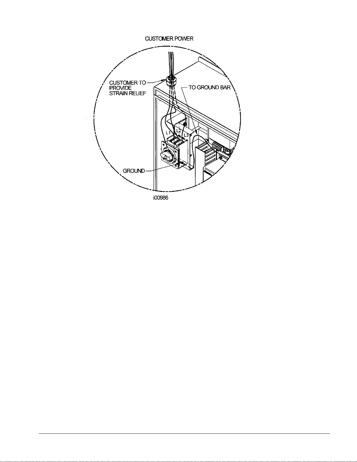
The 208-240 volts wires to the machine through the electrical box located on the back of the column. The
wire enters the main on/off switch through a hole on the top of the box. The ground wire should be
connected at the top or bottom of the breaker bracket.
Southwestern Industries recommends the machine be earth grounded by driving a copper rod into the
ground. It is the responsibility of the customer to install this rod.
2.10.1 Phase Converters
For those machines that will be run with a phase converter, it must be a CNC rated rotary type
rather than a static phase converters. CNC rated rotary phase converters allow for varying loads in
the system. A CNC rated phase converter also regulates the new leg created so it does not end up
being too high or low of a voltage. The electrical load on the machine will vary based on the type of
cut taken and the speed of the motor. Static phase converters can only be used on machines with a
non-varying load. Please contact your local phase converter distributor for precise sizing.
Note: Please connect the incoming ground wire to copper ground bar on left side of cabinet.
Page 23
17
TRAK Machine Tools
Southwestern Industries, Inc.
TRAK TRL Lathe, ProtoTRAK RLX CNC Safety, Installation, Maintenance, Service & Parts List
Figure 2.10 - Wiring the TRAK TRL Lathe
2.11 Air Connection
The TRAK machines have an air hookup in the rear of the machine only if they come with a CNC Turret
option.
The air regulator pressure is set to 90 psi at the factory for the turret unit.
2.12 Mounting the Display Pendant
The ProtoTRAK RLX display pendant mount differs depending on which lathe is being installed. The pendant
is held with 4 socket head cap screws. There is a locating screw on the pendant arm to help align the
pendant with the mounting holes.
Make sure the pendant rotates freely from side to side only on the 1845RX and 2470RX. On the 1630RX,
the pendant is stationary.
2.13 Cable Interconnections
All cable interconnections are made at the factory except for those connecting to the pendant display.
There are 2 cables that need to be connected to the pendant.
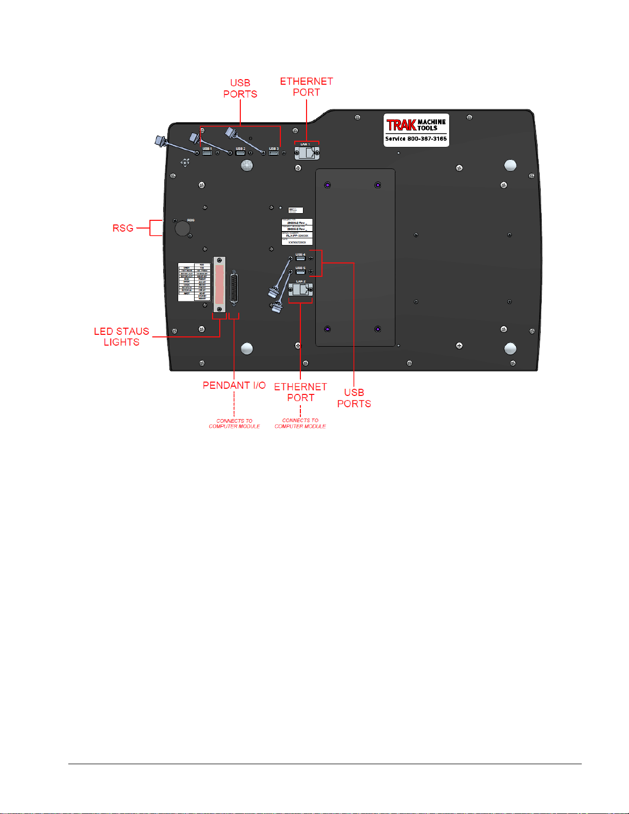
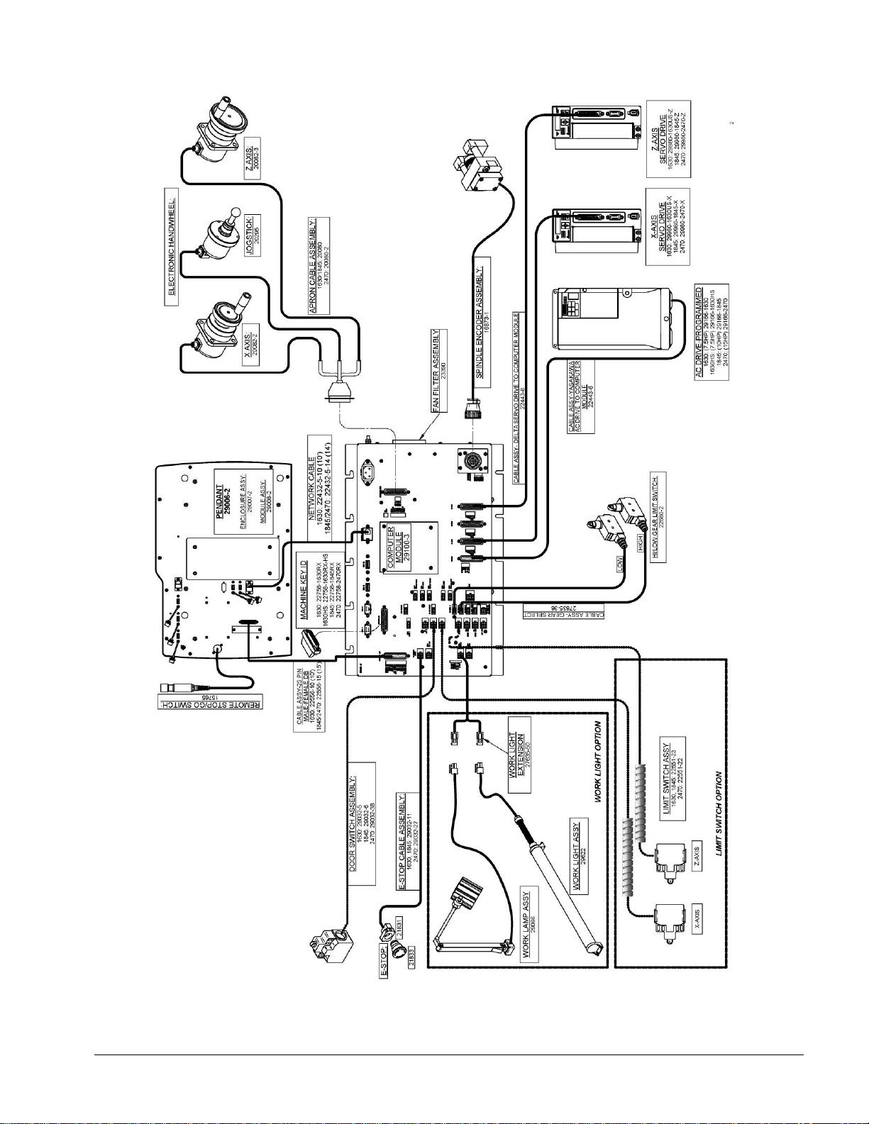
With the main power to the machine turned off, plug in the Pendant I/O cable (SWI 22556-15: DB25
connectors on both ends) and the Ethernet patch cable (SWI 22432-5-xx). Figure 2.13b shows the
connectors on the rear of the pendant.
Make sure there is sufficient slack in the cables for when the pendant is rotated about the pendant
arm. The following drawing describes all of the cable and other connections to the pendant.
Page 24
18
TRAK Machine Tools
Southwestern Industries, Inc.
TRAK TRL Lathe, ProtoTRAK RLX CNC Safety, Installation, Maintenance, Service & Parts List
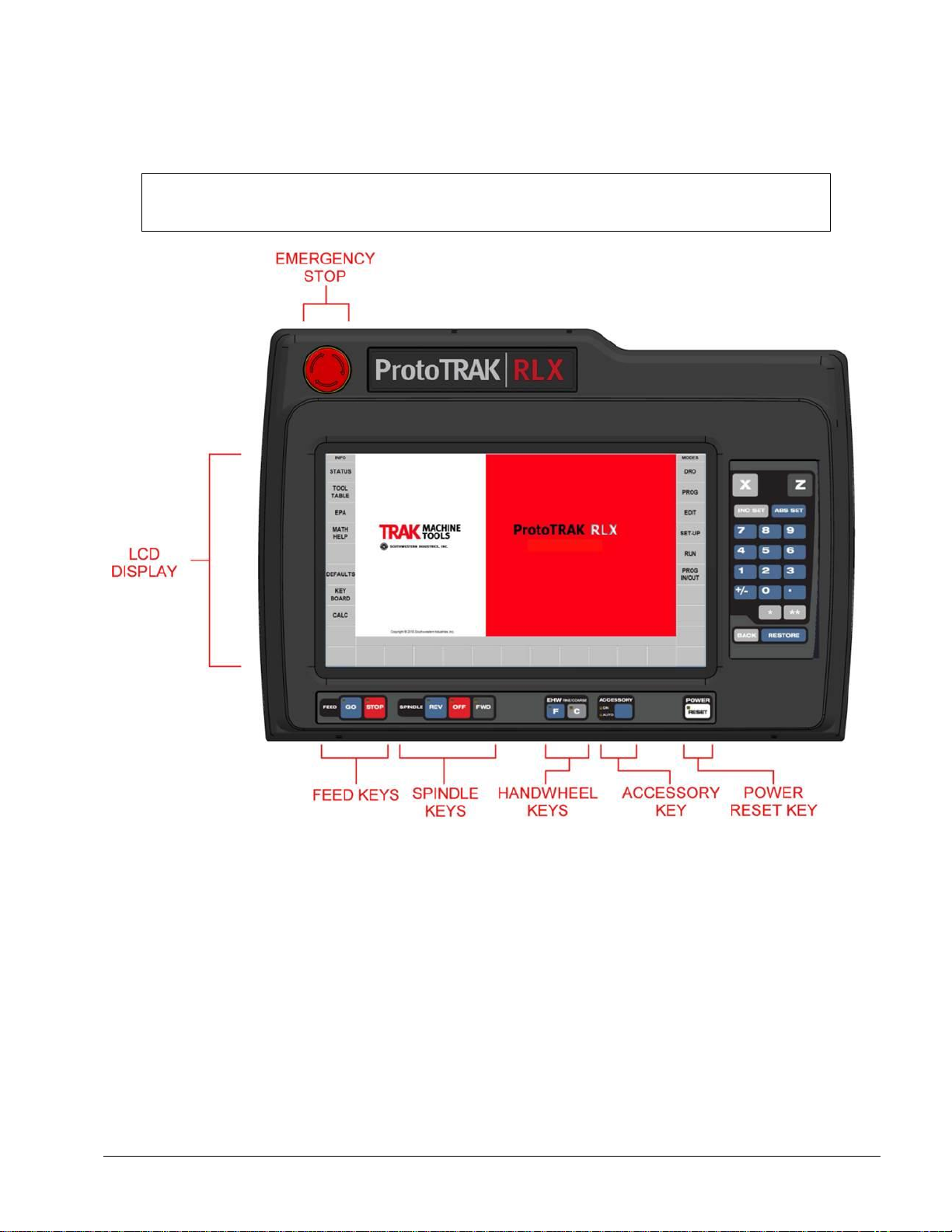
Make sure there is a hardware (option) key plugged into one of the USB ports of the pendant. This key
CAUTION!
Make sure the main power switch is turned off at the electrical cabinet before
plugging in the cables.
activates any converters or options ordered. The part number for this key is 23770-8. The key must be
programmed according to the type of machine it is on and the options ordered.
Figure 2.13a - RLX - Pendant Front Side - P/N 29008-2
Page 25
19
TRAK Machine Tools
Southwestern Industries, Inc.
TRAK TRL Lathe, ProtoTRAK RLX CNC Safety, Installation, Maintenance, Service & Parts List
Figure 2.13b - RLX - Pendant Back Side - P/N 29008-2
Page 26
20
TRAK Machine Tools
Southwestern Industries, Inc.
TRAK TRL Lathe, ProtoTRAK RLX CNC Safety, Installation, Maintenance, Service & Parts List
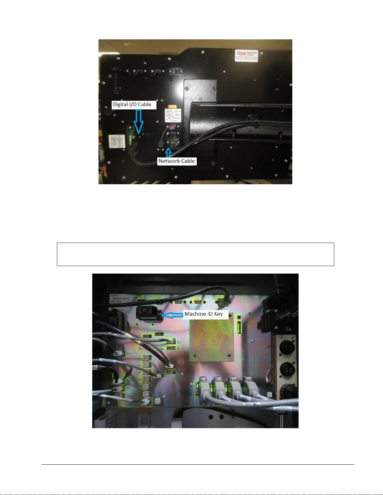
Figure 2.13c - RLX - Pendant Cable Connections
CAUTION!
Make sure the main power is turned off on the back of the electrical cabinet before
plugging in the cables.
2.14 Machine ID Key
Ensure that the Machine ID key is plugged into the port on the computer module inside the electrical
cabinet, or the machine will not run.
Figure 2.14 - RLX – Machine ID Key
Page 27

21
TRAK Machine Tools
Southwestern Industries, Inc.
TRAK TRL Lathe, ProtoTRAK RLX CNC Safety, Installation, Maintenance, Service & Parts List
2.15 Pendant Maintenance
2.15.1 How to Clean the Touchscreen
When cleaning the touchscreen, make sure to turn off the machine. You can use any window
cleaning solution to get any debris off of the screen. It is preferable to use a non-lint cloth when
cleaning.
Note – if you clean the screen with the power on, you may get false triggering or no touchscreen
detection at all.
Page 28
22
TRAK Machine Tools
Southwestern Industries, Inc.
TRAK TRL Lathe, ProtoTRAK RLX CNC Safety, Installation, Maintenance, Service & Parts List
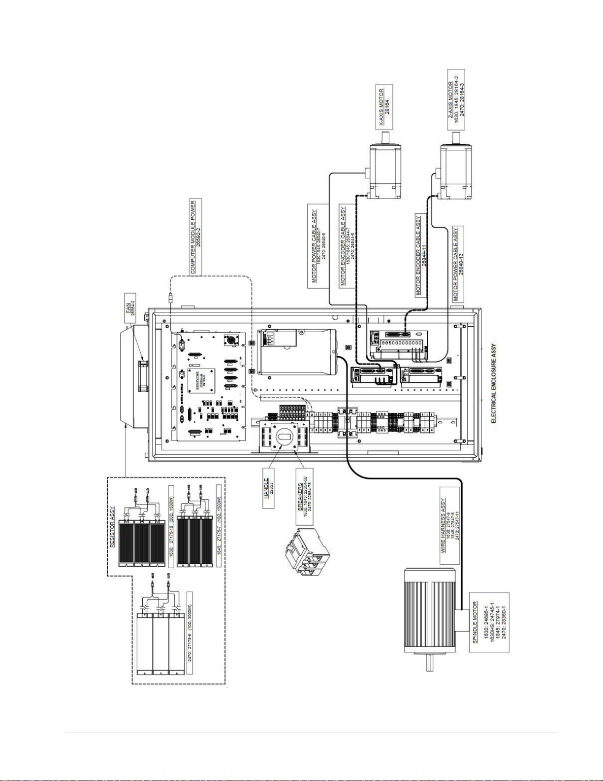
Figure 2.15.1 - RLX – Electrical Cabinet Connectivity
Page 29

23
TRAK Machine Tools
Southwestern Industries, Inc.
TRAK TRL Lathe, ProtoTRAK RLX CNC Safety, Installation, Maintenance, Service & Parts List
Parts List - TRAK TRL Lathes (Figure 2.15.1)
Item
1630RX
1630HSRX
1845SX
2470SX
Description
1
29980-
1630US-X
29980-
1630US-X
29980-1845-X
29980-2470-X
X Servo Drive
2
28164
28164
28164
28164
X-Axis Motor
3
29980-
1630US-Z
29980-
1630US-Z
29980-1845-Z
29980-2470-Z
Z Servo Drive
4
28164-2
28164-2
28164-2
28164-3
Z-Axis Motor
5
29166-1630
29166-1630
29166-1845
29166-2470
AC Drive
6
29100-3
29100-3
29100-3
29100-3
Computer Module
7
Spindle Control
Module
8
29008-2
29008-2
29008-2
29008-2
Pendant
Page 30
24
TRAK Machine Tools
Southwestern Industries, Inc.
TRAK TRL Lathe, ProtoTRAK RLX CNC Safety, Installation, Maintenance, Service & Parts List
Figure 2.15.2 - RLX – Computer Module Connectivity
Page 31

25
TRAK Machine Tools
Southwestern Industries, Inc.
TRAK TRL Lathe, ProtoTRAK RLX CNC Safety, Installation, Maintenance, Service & Parts List
2.16 Lubrication
CAUTION!
Failure to properly lubricate the lathe will result in the premature failure of ball screws
and sliding surfaces.
CAUTION!
Failure to manually activate the pump at the beginning of each day, or allowing the Auto
Lube to run dry may cause severe damage to the lathe way surfaces and ballscrews.
CAUTION!
Oil that is too heavy and viscous such as 50W or 90W oil can clog oil line tubing. Do not
mix detergent type automotive or multi-purpose oils with the Mobil Vactra Oil No.2 used
in this application.
The TRAK Lathe auto lube system provides centralized automatic lubrication for the carriage, cross slide and
ballscrews. The lube pump has a 2-liter reservoir filled with Mobil Vactra Oil No. 2 (ISO30).
The lube pump has electronic memory which acts as an internal clock to keep track of the running time of
the axis motor. Even when the spindle is turned off, the lube pumps internal clock will not reset. The
interval between pump cycles is based on axis motor movement time.
2.16.1 Lube Pump Operation
The pumping output can be regulated electronically to control the Interval Time between pumping
cycles, and the Discharge Time of each pumping cycle. The pump can also be run manually through
a key found under service codes. The following describes the steps used to program the lube pumps
Interval and Discharge times.
Start with using Service Code “E”.
Setting Interval Time: Service Code 301
Press "Mode", "Set up", "Service Codes", "C" (Machine Setup), Code 301, and then enter the
desired Interval time in minutes.
Setting Discharge Time: Service Code 302
Press "Mode", "Set up", "Service Codes", "C" (Machine Setup), Code 302, and then enter the
desired Discharge time in seconds.
To manually Pump Oil: Service Code 300
Press "Mode", "Set up", "Service Codes", press "E", and then press Code 300 (Lubrication Pump
Switch). The pump will pump oil for the amount of time programmed in Code 302. The spindle does
not need to be turned on.
2.16.2 Factory Default Values
Interval Time - 60 min
Discharge Time - 15 sec
Discharge Pressure - Approximately 100 - 150psi
To adjust the amount of Discharge Pressure displayed on the lube pump gauge, loosen the jam nut
and turn the adjustment screw located on the top right side of the lube pump while the lube pump
is activated. To activate the lube pump use Service Code 300.
Page 32
26
TRAK Machine Tools
Southwestern Industries, Inc.
TRAK TRL Lathe, ProtoTRAK RLX CNC Safety, Installation, Maintenance, Service & Parts List
2.16.3 1630RX, 1630 HSRX, 1845RX & 2470RX Headstock Oil
Reservoir
Oil will only be visible on the headstock site glass when the spindle is running. If oil is not flowing
to the site glass when the spindle is ON for either machine, stop running the spindle immediately
and call for service. Failure to do so may ruin the spindle bearings.
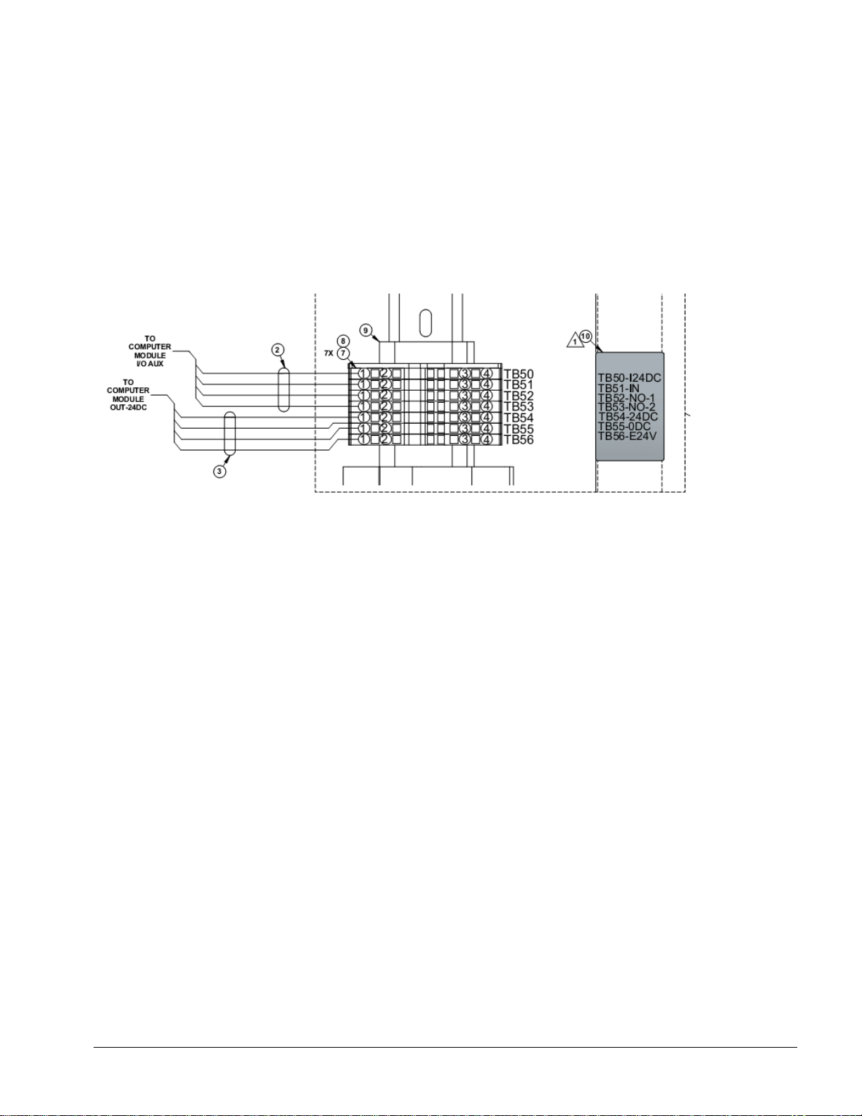
2.17 Auxiliary Output
An Auxiliary Option Kit is offered for the support +24VDC optional devices. Power and device control are
provided via the following terminal block found on a DIN rail in the upper left section of the electrical
cabinet.
Figure 2.17a – Auxiliary Output Connectivity
The Auxiliary Output control is a Normally Open (NO) contact. It is rated for 30 volts DC or AC for current of
up to 1 amp. This is provided via terminals TB52-NO-1 and TB53-NO-2 as shown in the above figure.
Terminal blocks TB54-24DC and TB55-0DC provide access to 24 volt power. This Auxiliary power can be
used to power a 24V Relay/Solenoid or other device through this Auxiliary Output. It is rated for 1 amp.
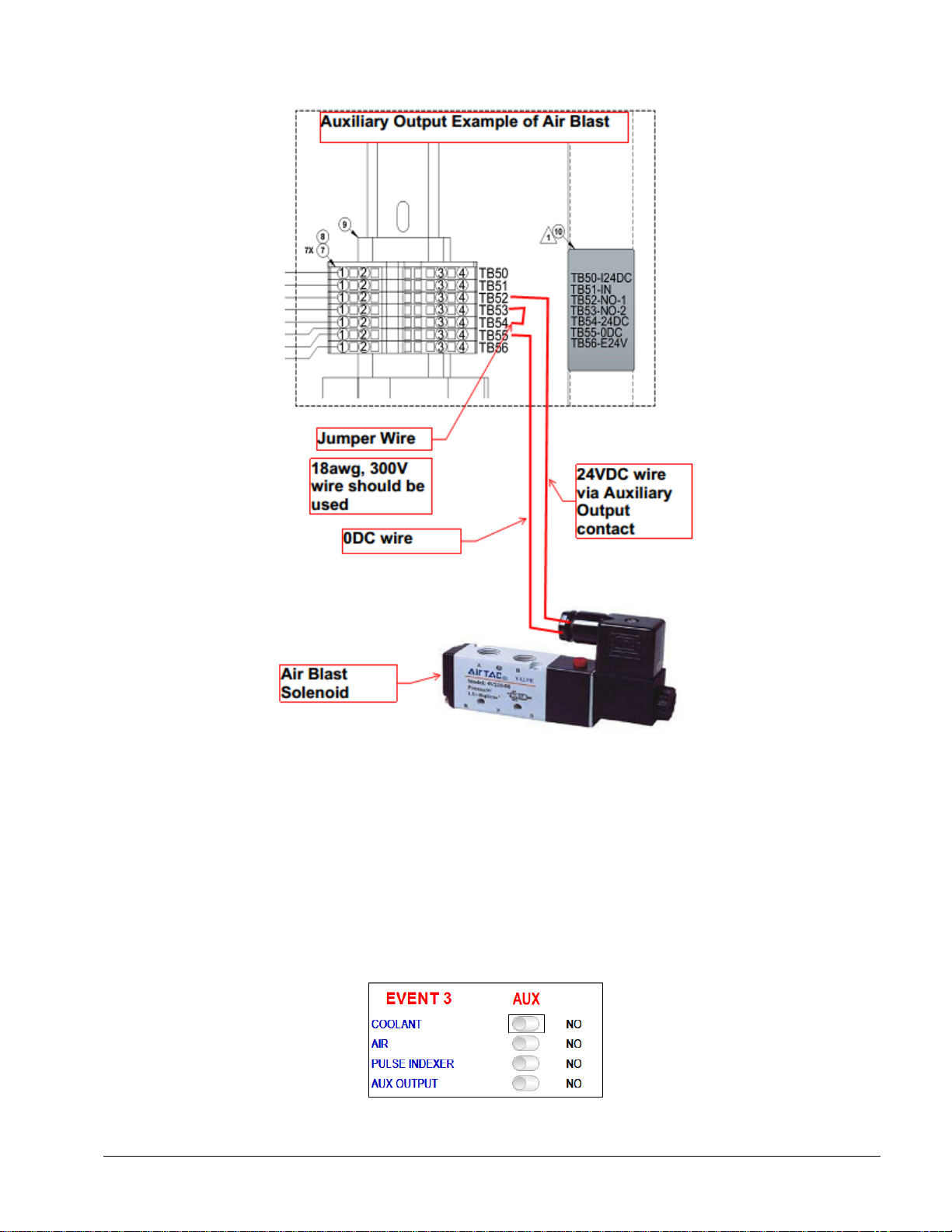
An Air Blast Solenoid is an example device which could be used with this Auxiliary Output Option. Auxiliary
24V will be turned OFF and ON via the Auxiliary Output when programmed with the AUX event.
Page 33
27
TRAK Machine Tools
Southwestern Industries, Inc.
TRAK TRL Lathe, ProtoTRAK RLX CNC Safety, Installation, Maintenance, Service & Parts List
Figure 2.17b – Auxiliary Output Example of Air Blast
Note: The Auxiliary Output relay is overwritten by the E-stop and/or Fault circuit. It will deactivate the relay
whenever there is an E-stop condition or when the software shuts OFF all the outputs due to a fault
condition.
This Auxiliary Output Option is enabled on the control system via the hardware Options Key. When enabled,
the Status screen will show a status of “Yes” for the Auxiliary Output. The use of code 318 will also show
the “Auxiliary Output” highlighted when enabled.
This software option turns on the AUX event and gives the user 4 outputs as shown below.
Page 34
28
TRAK Machine Tools
Southwestern Industries, Inc.
TRAK TRL Lathe, ProtoTRAK RLX CNC Safety, Installation, Maintenance, Service & Parts List
2.18 Cutting the Test Part
(See Figure 2.19)
Tools Required
Chuck
Tool Post
Tool Block
Tool Holder, right-hand face and turn type
In order to accurately machine the test part, the gears and bearings in the headstock must be properly
warmed and preloaded. This is accomplished by running the spindle for 15 to 25 minutes prior to cutting
the test bar at 500 RPM.
Load an approximately 2” dia. aluminum bar into the spindle chuck. Load a standard right hand face and
turning tool into a tool block. Align and lock the tool block onto the tool post. Set the depth of cut to a
maximum of .002.
Set the spindle to an acceptable speed for turning the test piece. A speed range from 650 to 950 RPM is
recommended.
2.19 Measurement of the Test Part
Tools Required:
O.D. Micrometers with .0001" graduations
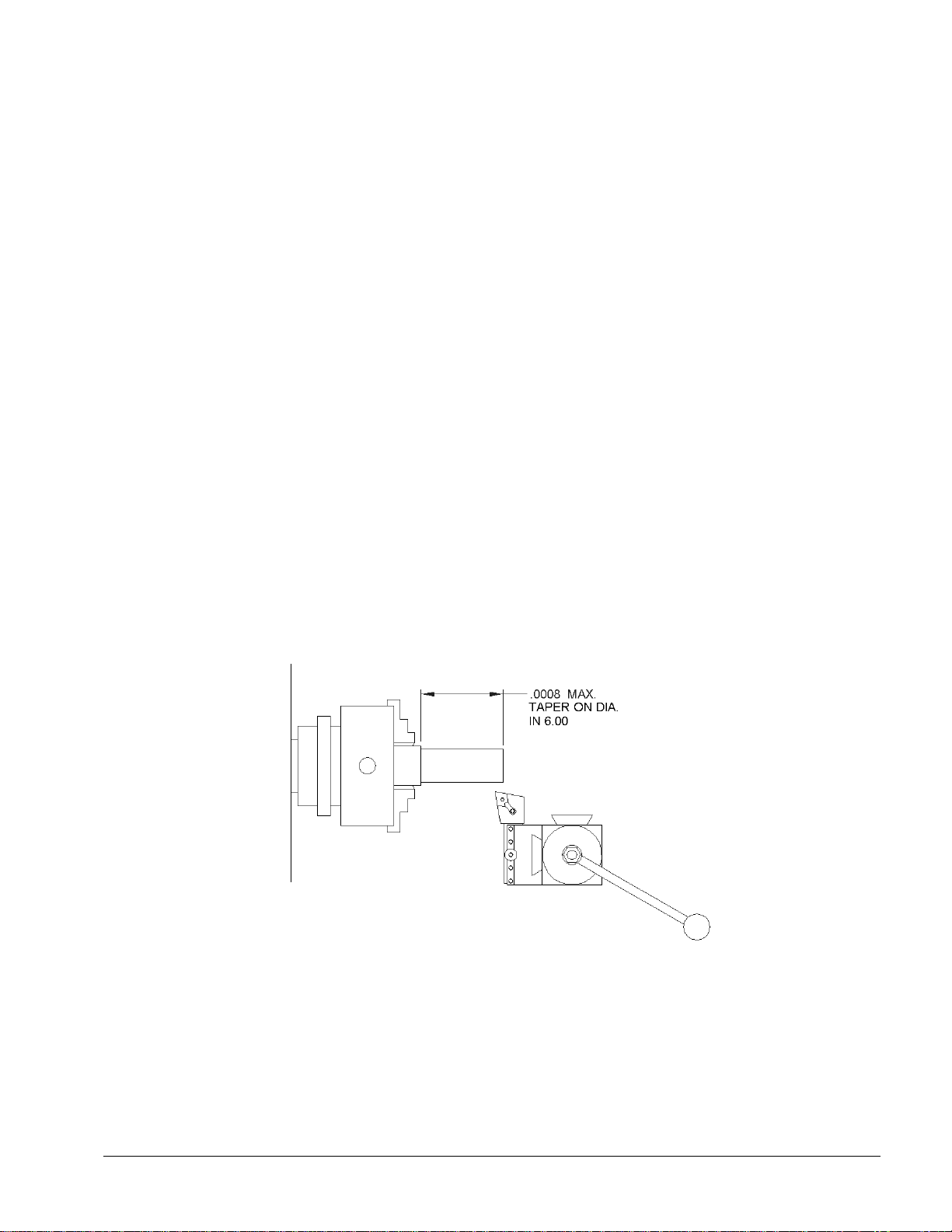
Using a calibrated O.D. micrometer with .0001" graduations, measure and record the generated dimension
at a 6.00 spacing. The acceptable measurement of parallelism of spindle axis to carriage movement (taper
of test piece) is .0008" over 6". If the taper measured is not acceptable, re-machine the test part and/or
check and adjust the level of the machine, or adjust the headstock.
Figure 2.19 - All TRAK TRL Lathes - Test Part
i00196
Page 35
29
TRAK Machine Tools
Southwestern Industries, Inc.
TRAK TRL Lathe, ProtoTRAK RLX CNC Safety, Installation, Maintenance, Service & Parts List
2.20 Mounting of an Buck Zero Set Chuck- RX Lathe
WARNING!
The Buck chuck requires a certain amount of torque to be properly mounted to the faceplate.
Please use the following chart to ensure safe operation and check the torque occasionally.
Improper installation of the chuck could result in injury or death. The 12” chuck sold from SWI
will come with a special wrench if installed in the field to adjust the chuck to the required
specifications.
Chuck Model
Mounting Bolt
Torque (foot pound)
8”
M10x1.5P
31.8 ft/lb
12”
M16x2P
137.4 ft/lb
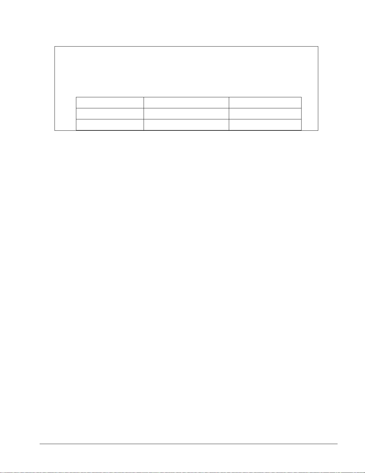
The 1630HSRX lathe has an Buck Zero Set spindle and requires a chuck of this type. Use the following
procedure to mount this style chuck. This chuck is also used on the 1630RX, 1845RX and 2470RX lathes.
Bolt the chuck adapter plate to the spindle with (4) M10 X 50 SHCS. The key on the spindle orientates the
adaptor.
Then bolt the chuck to the adaptor plate with (3) M8 x 70 SHCS. The chucks SWI provides are self-aligning
and need no adjustment.
Tools required;
Magnetic indicator base with a 0.0001” reading indicator
Cam lock wrench
Chuck wrench
Allen wrench 3/8”
Allen wrench 5/16”
Alignment bar
Lift for chuck
Tool post, tool holder and turning tool with insert
Procedure:
Note: this procedure needs to be performed after the spindle taper test
1. On lathes with gears, put in neutral for ease of spinning chuck.
2. Clean the face and outside taper of the spindle
3. Clean the face and inside taper of the adapter plate
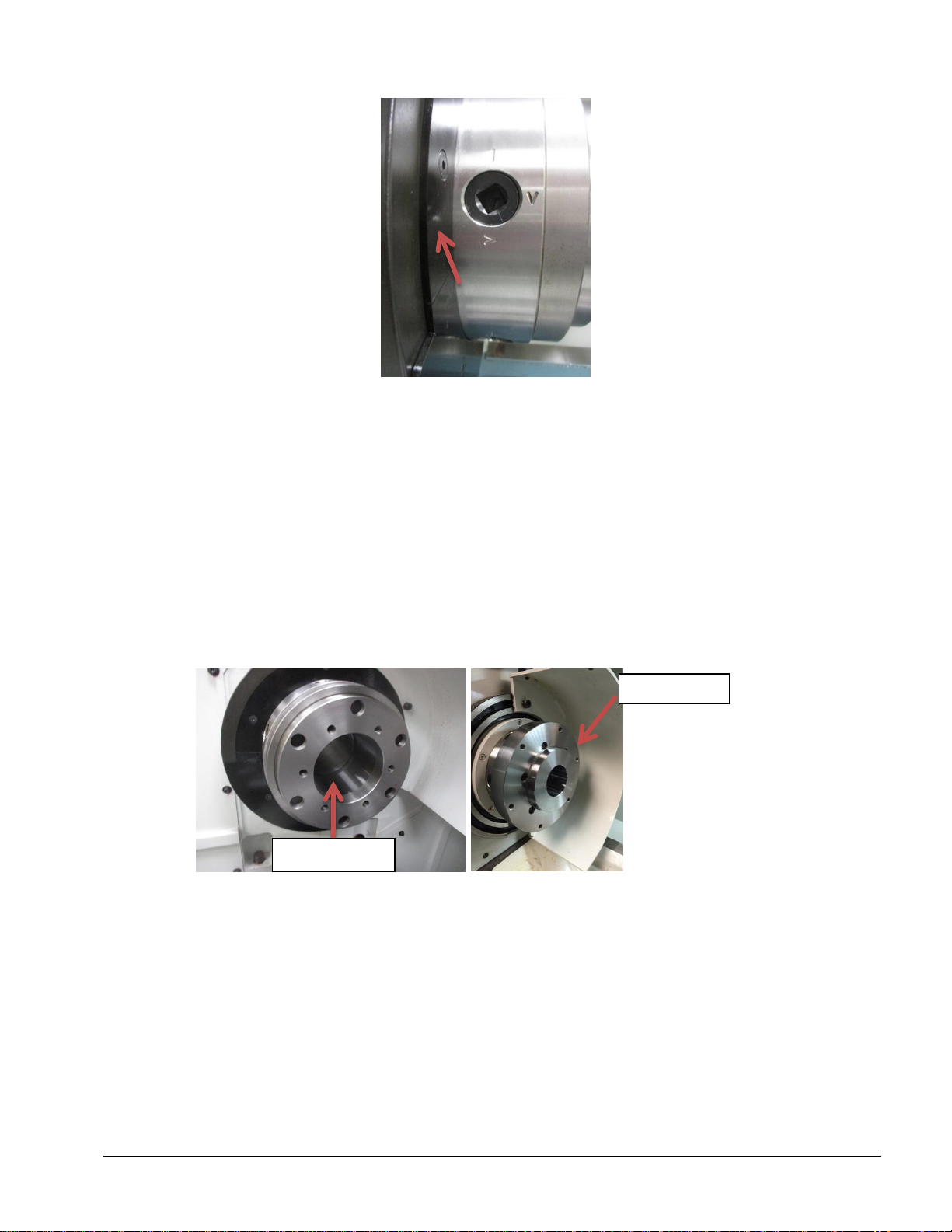
4. Verify the cam lock studs are set evenly and at the correct location. The groove on cam the lock
stud should line up with adapter plate.
5. Install the adapter plate onto the spindle
a. Snug the cam locks one at a time.
b. Once all 6 cam locks are adjusted, continue around tightening all cam locks
c. Continue around tightening the cam locks until no further movement of the cam locks is
detected
d. Check to verify the mark on the cam lock is between the marks on the spindle. See photo 1.
e. Verify there is no gap between the rear of the adapter plate and the face of the spindle.
Page 36
30
TRAK Machine Tools
Southwestern Industries, Inc.
TRAK TRL Lathe, ProtoTRAK RLX CNC Safety, Installation, Maintenance, Service & Parts List
For 12” chuck
For 8” chuck
Photo 1
6. True the adapter plate to the spindle.
Note 1: Make sure the carriage does not hit the chuck guard. If the chuck guard is removed, use
Loctite #242 when reattaching fasteners
a. Install tool post, tool holder and tool with insert. Note: if the machine has a turret, you do not
need to install the tool post and holder. Simply install the tool directly into the turret.
b. Enter DRO mode
c. Set spindle speed to 500 RPM
d. Press spindle “FWD”
e. Manually move the tool until it contacts the adapter in the Z-axis where the chuck mounts at the
location of the mounting holes
Photo 2 Photo 3
f. Move the X-axis inward until it clears the material by entering the relief where the taper
intersects the mounting flange or clears the surface
g. Manually move the Z-axis towards the spindle by 0.004”
h. Zero the X and Z readouts.
i. Press “Power Feed” soft key.
j. Using the override keys, reduce the feed rate to 2.0
k. Press “X”, “5”, “INC SET”
l. Press “GO”
m. When the cutter clears the part, press STOP and verify the surface has cleaned up.
Page 37
31
TRAK Machine Tools
Southwestern Industries, Inc.
TRAK TRL Lathe, ProtoTRAK RLX CNC Safety, Installation, Maintenance, Service & Parts List
n. Clear the tool and carriage and remove tool.
WARNING!
Use only chucks which are rated to the maximum RPM of the lathe.
7. Install the chuck.
a. Clean the chuck thoroughly and visually inspect for imperfections. Elevate any issues to your
supervisor.
b. Adjust the four set screws around the outside of the chuck so they do not protrude into the
inside cavity on the rear of the chuck
c. Using lift, raise the chuck and locate against the backing plate.
d. Rotate spindle until the holes in the chuck align with the holes in the backing plate
e. Install the 6 screws and remove the lift.
8. Trueing the chuck.
a. Snug the 6 bolts in the face of the chuck to prevent the chuck from slipping
b. Adjust the 4 fine adjustment set screws around the periphery until they contact the adapter
plate and then back out one turn.
c. Open chuck and clean jaws thoroughly
d. Install alignment bar so there is approximately 6” protruding from chuck.
e. Using your indicator and the 4 fine adjustment set screws, adjust the chuck until the alignment
bar is running within 0.0005” 1” from chuck.
i. While adjusting the set screws, rotate the spindle so the set screws align with the indicator.
When the indicator reads low, tighten the set screw and when the indicator
reads high, loosen the set screw.
f. Move the indicator 6” from chuck and check runout. Max. runout is 0.0015”
g. Tighten 6 screws in face and 4 set screws as required to obtain these readings.
h. Torque the 6 screws in the face of the chuck to 38 ft-lbs for 8” chuck and 75 ft-lbs for the 12”
chuck.
i. You will need to go from the 1” from the chuck and 6” from the chuck multiple times to obtain
0.0005” at 1” from chuck and 0.0015” 6” from chuck.
j. Place your indicator on the outside diameter of the chuck and measure the total runout.
Maximum runout of the chuck body cannot exceed 0.004”.
k. Remove alignment bar.
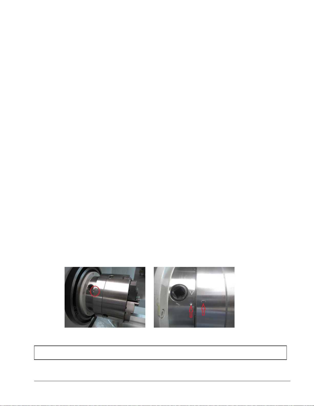
l. Using a die grinder and a ¼” round nose double cut carbide burr, make a small mark on the
spindle for orientation. See photo 4 and 5
m. Using a stamp, make a mark on the adapter plate for clocking of chuck when it is removed and
then re-installed onto spindle. See photo 4 and 5.
Photo 4 Photo 5
Page 38

32
TRAK Machine Tools
Southwestern Industries, Inc.
TRAK TRL Lathe, ProtoTRAK RLX CNC Safety, Installation, Maintenance, Service & Parts List
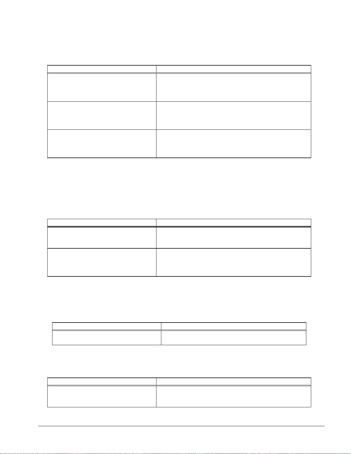
3.0 Troubleshooting by Symptom
Possible Cause
Check This
Ethernet Cable Not Properly Connected
Windows error “There is a problem with the network
adapter: Media Disconnected” will show on the screen for
a cable issue.
Check the Ethernet cable is properly connected to both
the Pendant and Computer Module (disconnect and
reconnect)
Ensure the Pendant side is the proper Ethernet port
(closer to the bottom of Pendant)
Need to Power Cycle the Pendant
Try rebooting the control to solve the problem
Recent changes to the network or
network settings
Review settings and return to original status to see if this
solves the issue
Windows OS does not see the network
connection
In the Windows Control Panel, view the Network and
Sharing Center. The Connection diagram should show the
network connection. Replace the network cable to see if
the network connection is found.
Replace the Pendant if none of the above resolve the
issue
Possible Cause
Check This
Start with troubleshooting in the
previous section.
Power cycle the Pendant/Computer Module.
Replace the Computer Module if the same Error and Fault
persists.
Use this section to begin the process of resolving a service problem. Each problem type is described in a
few words and then more fully described in an explanatory paragraph. Following this is a chart that directs
in the most logical steps.
3.1 Problems Related to the Pendant and Computer Module
3.1.1 Pendant will not Connect to Motion Control in Computer Module at
Boot Up
This symptom can happen during boot up or when the machine was connected it may disconnect
and you may see a flashing message on the screen.
3.1.2 Pendant will not Connect to Motion Control in Computer Module
This symptom can happen during boot up or when the machine is connected. The unit may
disconnect and a flashing message on the screen and a Fault Message such as “Unable to
communicate with Motion Control…”
Page 39
33
TRAK Machine Tools
Southwestern Industries, Inc.
TRAK TRL Lathe, ProtoTRAK RLX CNC Safety, Installation, Maintenance, Service & Parts List
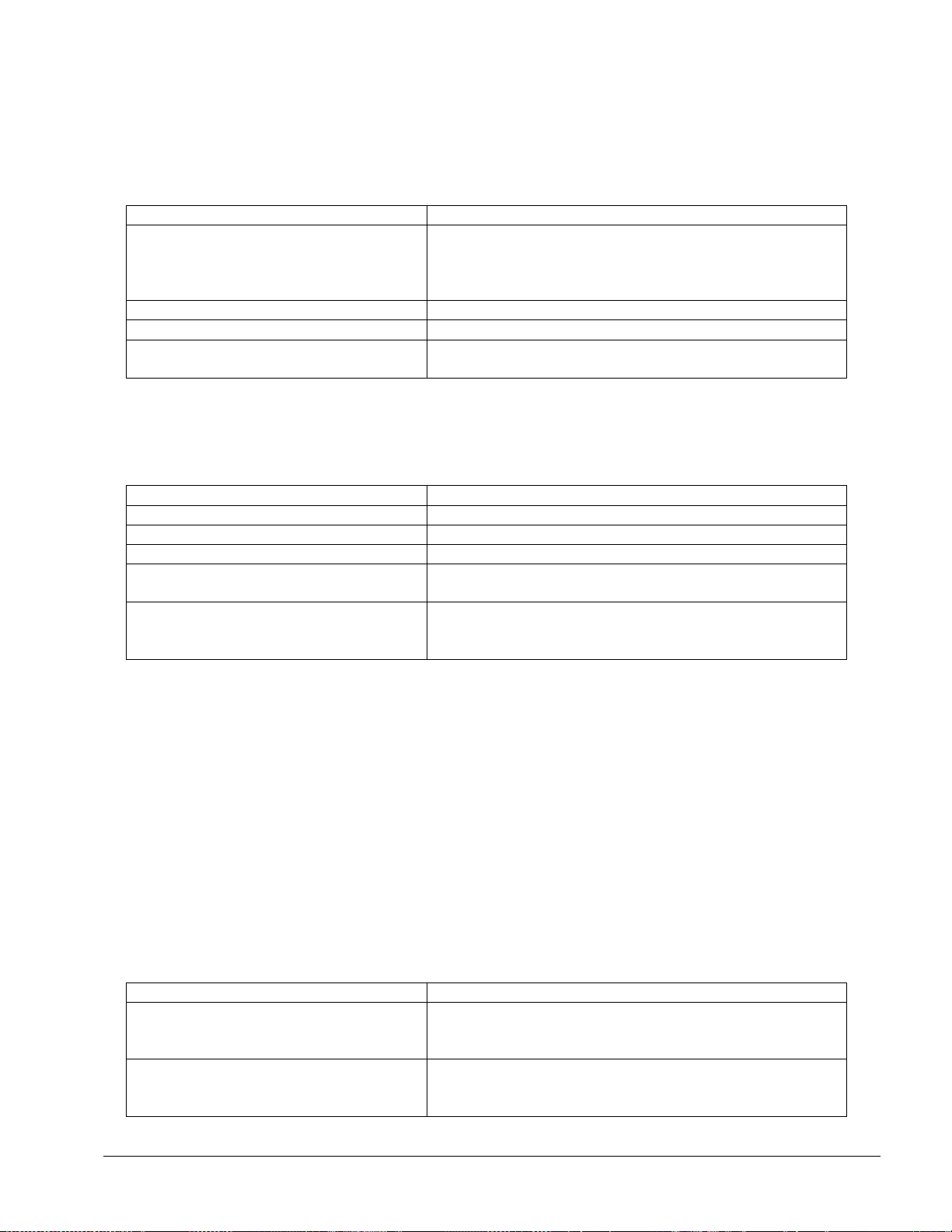
3.1.3 Pendant Does Not Power On
Possible Cause
Check This
No Power To the Pendant
Check the I/O Cable (DB25 Connector) cable is connected
to both the Pendant and the Computer Module.
Disconnect the cable and verify there are no bent pins or
sockets pushed out of position in the connectors.
No Power on the Computer Module
On the Computer Module, check the status LED labeled
+24VDC next to the I/O Cable from the Pendant. If the
LED is off, check the power input to the Computer
Module.
Power Problem in the Pendant
On the rear of the Pendant, review the Status LED group.
All three of the power LEDs should be on: 24VDC, 12VDC
and 5VDC. If one or two of the LEDs are not ON, replace
the pendant.
Possible Cause
Check This
LCD Backlight Issue
Use a flashlight to shine light on the LCD screen. If
character/graphics can be seen, the Pendant should be
replaced.
Power Problem in the Pendant
On the rear of the Pendant, review the Status LED group.
All three of the power LEDs should be on: 24VDC, 12VDC
and 5VDC. If one or two of the LEDs are not ON, replace
the pendant.
Possible Cause
Check This
Poor cable connection in Pendant
Check Power LEDs as in 3.1.4.1
Replace Pendant if issue is not resolved.
Possible Cause
Check This
RSG Connection
Disconnect the RSG and confirm the pins/sockets on the
connectors of the RSG and Pendant are not bent or
pushed in. Reconnect the RSG.
This issue may be caused by a lack of power to the Pendant
3.1.4 Screen Problems
3.1.4.1 Screen is Blank but LCD Backlight is Visible
To check for this symptom, Use a flashlight to see if you can see our software running in the
background. This means that the pendant module needs to be replaced.
3.1.4.2 Bad Picture on the Display
The display has strange characters, horizontal bars or other unfamiliar images, or the display
continually rolls.
3.1.5 RSG Button Does Not Work
Page 40

34
TRAK Machine Tools
Southwestern Industries, Inc.
TRAK TRL Lathe, ProtoTRAK RLX CNC Safety, Installation, Maintenance, Service & Parts List
Internal Pendant Issue
Jumper across the two metal sockets on the RSG
connection on the Pendant. Review the LED status “RSGBT” on the rear of the Pendant. The LED should be ON.
If this is not the case, replace the Pendant.
Possible Cause
Check This
Software not seeing the Key Press
Press any of the numeric keys. Confirm the “Key Press”
LED in the status LEDs group on the rear of the Pendant
is ON while the key is pressed. If this does not happen,
power cycle the power and repeat. Perform the next test
below.
Keypad not functioning
Use Service Code 81 to determine if any the keys are not
functioning. Replace the Pendant if any keys are nonfunction or intermittent functionally.
Possible Cause
Check This
Software not seeing the Key Press
Press any of the numeric keys. Confirm the associated
LED in the status LEDs group on the rear of the Pendant
is ON while the key is pressed. If this does not happen,
power cycle the power and repeat. Replace the Pendant
if the problem still exists.
Possible Cause
Check This
Switch Connection Issue
Check the door guards are connected at the Computer
Module. Disconnect and reconnect. Power cycle the
Computer Module. Use Service Code 521 to see all the
inputs.
Internal Issue
With the door guard closed, verify LED Status GRD3 is
ON. If this is not working, jumper across the input on the
Computer Module. If this LED does not come On or the
“DOOR OPEN” message persists, replace the Computer
Module.
3.1.6 System Does Not Respond to Numeric Keys Button Presses
The Numeric Keys are the keys to the right of the LCD screen. (This does not include the keys
below the screen.)
3.1.7 System Does Not Respond to Critical Keys Button Presses
The Critical Keys overlay is found below the touchscreen.
3.1.8 Door Guards Not Working Properly
On USA machines, door guards are turned off by default. Make sure they are turned on, if you have
this option installed, by using service code 331. Door guard switches are wired Normally Open.
Page 41
35
TRAK Machine Tools
Southwestern Industries, Inc.
TRAK TRL Lathe, ProtoTRAK RLX CNC Safety, Installation, Maintenance, Service & Parts List
3.1.9 Power Reset Button is Not Working
Possible Cause
Check This
E-Stop Engaged/Remote E-Stop Engaged
Disengage the E-Stop button and repeat using the Power
Reset Button.
Check the Remote-E-Stop is properly connected and the
unit is not damaged.
Fault Messages
Attend to and clear any displayed Fault Message
Keypad Issue
Refer to Critical Keys Issues Above in Section 3.1.7
Power cycle the unit. If all above do not resolve the
issue, replace the Pendant.
Possible Cause
Check This
Invalid User Mode for Spindle Control
Check the User Mode
Axis Fault
Confirm can job each axis.
Keypad Issue
Refer to Critical Keys Issues Above
Power cycle the unit. If all above do not resolve the
issue, replace the Pendant.
Check the AC Drive to Computer Module Connections.
Verify the E-Stop is not actuated as well as the NC Ready
key is engaged.
Possible Cause
Check This
Remote Stop-Go (RSG) switch has a
short (if connected)
Remove the RSG. Turn the system off and then on again.
If the problem goes away and then re-appears when the
RSG is plugged-in, replace the RSG.
Pendant Non-Responsive
Reboot control and see if problem goes away. If it does,
continue to operate the Pendant.
Use Service Code 521 to verify the correct LEDs are ON.
The power reset button must be pressed to energize the servos and spindle. This must be done
upon power up, or following the use of the E-Stop button or whenever an M abort (critical fault)
message happens.
3.1.10 Spindle Does Not Turn ON
The user presses the FWD or REV buttons on the pendant and the spindle does not come on.
3.1.11 Pendant Does not Respond and Appears to be Locked Up
During normal operation, one of the follow symptoms occurs so that the Pendant is non-responsive;
No Beep when any button is pressed or touch screen is pressed
Screen does not change when touched
USB Keyboard does NOT respond.
Pressing E-stop Stops the axis but Pendant does not change screen.
Numeric Key press does not cause the Key Press LED to turn ON.
Removing Computer module Network does not change Lock-up condition.
Page 42
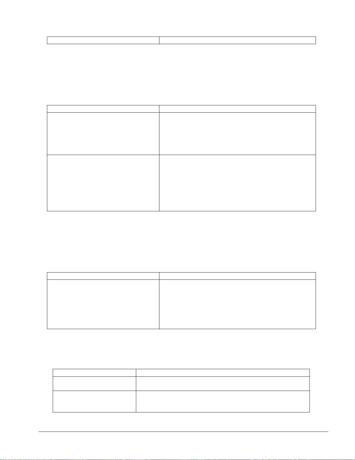
36
TRAK Machine Tools
Southwestern Industries, Inc.
TRAK TRL Lathe, ProtoTRAK RLX CNC Safety, Installation, Maintenance, Service & Parts List
If the problem returns, replace the Pendant Module
Possible Cause
Check This
E-Stop Switch Failure
Confirm E-Stop is not engaged.
Verify all cable connections to Pendant and Computer
Module are correct.
Confirm “E-Stop” LED is ON in the LED Status group on
the rear of the unit only when E-Stop is engaged.
Replace Pendant if the above does not resolve the issue
Wiring Faulting
For a constant E-Stop message and the LED’s on the
computer module are all off, check the remote E-stop
cable and connections. Take a cable like the door switch
cable and plug it into the remote E-Stop connector. If the
LED for this comes on and the 2 pendant E-Stop LEDs
come on, then the remote E-Stop cable or wiring is at
fault.
Possible Cause
Check This
Internal connection Issue
A “touch dot” should appear on the screen where contact
with the screen is made.
For touching the softkeys, a beep is generated by the
Pendant on touching the key. (The info area of the
screen does not generate a beep sound.)
Power cycle the Pendant. If the problem persists, replace
the Pendant
Possible Cause
Troubleshooting procedure and possible causes.
Device Driver Not Installed
Device driver not installed for USB device. Run service code 540
and load USB driver.
One single USB or all USB
connections are not working
with any device
For a previously working USB port, and no device functions using
the port, power cycle the control system.
If the problem persists, replace the Pendant Module
3.1.12 E-Stop Error (Machine Is Disabled)
The E-Stop turns the power off to the axis and spindle motors. On the RX control system, the
message that is displayed when a user presses the E-Stop button is as follows: “ Servos not enabled
– Please press power reset button on the front panel to enable the servos”.
3.1.13 Touchscreen Does Not Respond
This means when the user presses the screen, there is no feedback from the touchscreen. When
the touchscreen is working properly, every touch of the screen produces a noticeable “touch dot” on
the screen. When you see this touch dot, it means the operating system sees the touch. If this
touch dot is not present then the OS has not seen it nor has our software.
3.1.14 USB Not working on Pendant
When plugging in a USB device the control does not recognize it.
Page 43
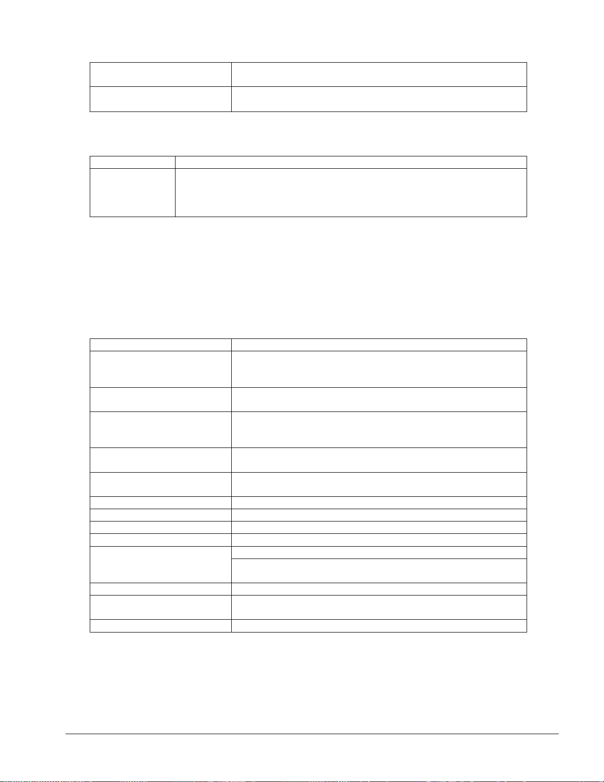
37
TRAK Machine Tools
Southwestern Industries, Inc.
TRAK TRL Lathe, ProtoTRAK RLX CNC Safety, Installation, Maintenance, Service & Parts List
USB Manufacturer
SWI recommends only the brand and model it offers to the
customer.
USB Drive Full
Check for free space remaining on the drive.
Symptom
Troubleshooting procedure and possible causes.
No network
connectivity
For either of the network ports not functioning, disconnect and reconnect
both ends of the cable. Reboot control and see if problem persists.
Repeat with a new, known good cable.
If the problem persists, replace the Pendant.
Symptom
Troubleshooting procedure and possible causes.
Servo cables at Computer
Module switched around.
Check cable connections, especially the encoder cable to the
motor, both ends of cable. If the cable was loose or had a poor
connection, fix problem and power cycle the machine.
X and Z-axis Gibs are
adjusted extremely tight
Check the adjustment of the X and Z-axis Gibs using the X and
Z-axis Gib adjustment procedures.
X and Z-axis Gibs are
adjusted extremely tight
Check the adjustment of the X and Z-axis Gibs using the X and
Z-axis Gib adjustment procedures. See X and Z-axis Gib
Adjustments Section 5.2.1
Excessive friction in the
slideways
See Machine Tool & Setup Section 4.1
Binding or looseness in the
Drive Train
See Mechanical Drive Train (X, Z) Section 4.2
Incoming electrical power
Incoming voltage. See Electrical Section 4.6
Servo Drive failure
See Servo Driver - Section 4.5
Motor failure
See Motor diagnostics, Section 4.4
Computer/Pendant failure
See Computer/Pendant diagnostics, Section 4.3
Error code 96(X-axis), 97(Y-axis) or 98(Z-axis)
(NFLT) LED on the computer module is for that particular axis is
OFF
Error occurs when going into DRO mode or Run mode
Error is displayed on the Drive all the time even after power
reset.
Solution
Failed Servo Drive
3.1.15 LAN Port Not working on Pendant
3.1.16 Axis Fault
Perform the following Service Codes and procedures:
Code 33 Software Identification. This is needed if you call SWI Customer Service.
The following symptom has to do with the servo drive showing a fault number on the digital LED.
See section 4.5 for a list of fault codes for the servos
3.1.17 Will Not Hold Calibration
The control will not hold calibration. Go to the "Configuration Values" screen and write down the
calibration values for the motor encoders. The calibration values are written in Hexadecimal.
Page 44
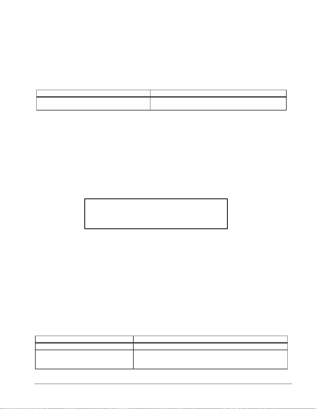
38
TRAK Machine Tools
Southwestern Industries, Inc.
TRAK TRL Lathe, ProtoTRAK RLX CNC Safety, Installation, Maintenance, Service & Parts List
Recalibrate the system and see if the values change. Turn the system off and on and see if the
Possible Cause
Check This
Not saving Calibration values
Replace the Computer Module.
See Computer/Pendant
Possible Cause
Check This
Limit Switches are triggered
Reset the Limit Switches using the procedures described above.
Poor Limit Switch Cable connection
Check for any pins that are loose, pushed in, or bent. Verify that
there is a good connection between the cable and the Auxiliary
Module.
Critical Error 5252: Limit Switch Active
The X-axis Limit Switch is activated.
Use the Handwheels to Move off the Switch.
values are held.
Perform the following service codes and procedures:
o Code 33 Software Identification. This is needed if you call SWI Customer Service.
o Code 313 Configuration Values.
o Code 123 Calibration Mode.
If calibration factors are being saved, but the measurements are not repeating or are not accurate:
See Measurements Are Not Repeating (Section 3.4.1)
See Measurements Are Not Accurate (Section 3.4.2)
3.1.18 Limit Switch Error
Limit switches are installed on the carriage and cross slide to prevent serious damage to the
machine in the event of a crash. The limit switch will trigger when carriage or cross slide moves
past the available travel. In the event a limit switch is triggered, the following error message will be
displayed.
When this happens, the control will not allow the operator to continue to manually move the
carriage or cross slide in the same direction.
To return the machine to its normal state of operation, perform the following procedure:
1. Use the electronic hand wheel to move the carriage or cross slide off the limit switch.
2. Press the "Mode" or "Return" key to reset the control.
3. Press the "DRO" key to enable the machine to once again jog.
Perform the following service code and procedure:
Code 312 Toggles limit switches on/off – this will turn the limit switches on or off. This is a
temporary fix for the problem and allows the user to run the machine until a replacement part
can be installed. If the limit switches are turned off and a problem occurs because of a crash,
this will not be covered under warranty.
Page 45

39
TRAK Machine Tools
Southwestern Industries, Inc.
TRAK TRL Lathe, ProtoTRAK RLX CNC Safety, Installation, Maintenance, Service & Parts List
Limit Switch failure
Try this
Switch 2 limit switch cables on the
auxiliary module in the electrics box.
Turn off all power to the machine. For the positive direction,
check for continuity between pins 1 and 6 on the Limit Switch
cable connector. You should hear a continuous beep from your
Multi-meter. By hand, manually depress the plunger on the limit
switch responsible for when the table, saddle, or ram is moving
in the positive direction. The beep from your Multi-meter should
stop beeping. This means the Limit Switch is triggering properly
for the positive direction. For the negative direction, repeat the
same procedure as described above using pins 5 and 9 on the
Limit Switch cable connector.
Does the limit switch problem move to the other axis? If it does
then the switch is most likely the problem. If it stays with the
original axis then it could be the auxiliary module or computer
module. See below.
Limit switch jumpers in cable breakout
box are making poor contact
Remove and reseat jumpers
3.2 Problems Relating to Machining Results
Possible Cause
Check This
Inadequate or no Lubrication to
Ballscrews and Way surfaces
Make sure all the Way surfaces are getting proper
lubrication. If not, check to make sure that the lube pump
is functioning properly. Also check for any pinched or
blocked oil lines.
X & Z-axis Drive Trains are loose
Check Repeatability using the Repeatability and Positional
Accuracy procedure. Step by step, carefully inspect the
Drive Train for any looseness. It may be necessary to
disassemble and then reassemble the Drive Train. See
Mechanical Drive Train (X, Z) Section 4.2
Way surfaces are pocked, scarred, or
excessively worn
Visually check the condition of all the Way surfaces. For
machines that may have excessively worn Way surfaces
you may need to adjust the Gibs in this area. This will
affect performance when using the machine outside of
this area. Check lubrication to affected areas.
Machine set-up problem
Machine’s feet are not equally supporting weight. See
Leveling, Section 2.9.
Verify the tool holder is correctly centered to the dead
center of the spindle as well as the tail stock.
Tooling problem
Improper tooling, Work piece not properly supported
speeds too fast, Feeds too slow.
3.2.1 Poor Finish
Poor finish can be caused by a number of variables including: speeds, feeds, tooling, machine setup
and chatter.
Perform the following Service Codes:
Code 33 Software Identification. This is needed if you call SWI Customer Service.
Code 131 Manual DRO. Used to move the axes to verify the encoders are counting.
Code 127 Measures backlash in the system.
Code 128 Enter backlash compensation.
Page 46
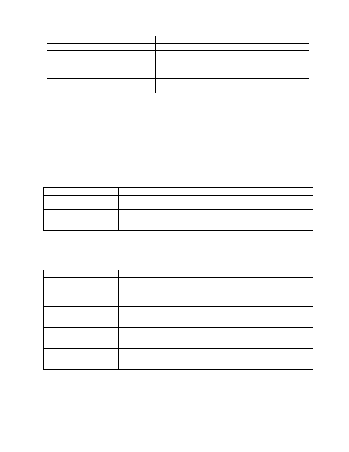
40
TRAK Machine Tools
Southwestern Industries, Inc.
TRAK TRL Lathe, ProtoTRAK RLX CNC Safety, Installation, Maintenance, Service & Parts List
See Machine Tool & Setup, Section 4.1
X gib too tight or loose
See Gib Adjustment, Section 5.2.1
Loose bearing problem
Looseness in the spindle bearings. Adjust spindle preload.
Ball screw misalignment,
See Mechanical Drive Train (X, Z), Section 4.2. See
Spindle Bearing Preload, Section 5.1.17
Poor Thread Finish
Use Service Code 510 to verify the encounter count
matches the RPM selected on the Pendant
Possible Cause
Check This
Tooling problem
Improper tooling, workpiece not properly supported.
See Machine Tool & Setup, Section 4.1
Loose bearing problem
Looseness in the spindle bearings. See Mechanical Drive Train (X, Z),
Section 4.2. Spindle bearing not preloaded correctly. Reseat bearing and
preload. See Adjust Spindle Bearing Preload, Section 5.1.17
Possible Cause
Check This
Machine set-up problem
Machine not leveled properly
See Leveling - Section 2.9
Tooling problem
Improper tooling; Work piece not properly supported. Use steady rest or
follow rest, reduce overhang from chuck headstock or tailstock.
Looseness in the gib or
misalignment of ball screw
Gib adjustment.
See Gib Adjustment - Section 5.2.1
See Z Ball screw Alignment - Section 5.1.15
Loose bearing problem
Looseness in the spindle bearings.
See Mechanical Drive Train (X, Z) - 4.2
See Spindle Bearing Preload - Section 5.1.17
Headstock and/or tailstock
not aligned
See Adjust Headstock for Taper - Section 5.1.16
To adjust tailstock from side to side, adjust grub screw. See Section
5.1.18
3.2.2 Turning Diameters Out of Round
Parts are not round within .0004” TIR for 2470, .0006” TIR for the 1630RX and 1845RX, and
0.0002” for the 1630HSRX. Runout for the spindle is best measured by using a .0001” dial indicator
and mounting to the inside taper of the spindle. Rotate the spindle and measure the indicator
movement.
NOTE: The typical geared head engine lathe is not capable of more precise diameters. Careful
adjustments to this turning machine will insure to maintain this accuracy. Better accuracy should
not be expected from a lathe of this class.
Perform the following service code and procedures:
3.2.3 Cutting Taper
Parts are considered to be cutting on a taper if there is a difference in diameter of more than .0008”
over 6 inches. This is best measured by using a .0001” micrometer.
3.2.4 Parts Have Incorrect Dimensions
Parts are being machined with dimensions that are different than those programmed. Typical
accuracy expectations should be:
Page 47

41
TRAK Machine Tools
Southwestern Industries, Inc.
TRAK TRL Lathe, ProtoTRAK RLX CNC Safety, Installation, Maintenance, Service & Parts List
Parts should be round within .0004” TIR on 2470RX, .0006” TIR on 1630RX and 1845RX,
0.0002” on 1630HSRX.
The acceptable measurement of parallelism of spindle axis to carriage movement is .0008” over
6 inches.
Page 48
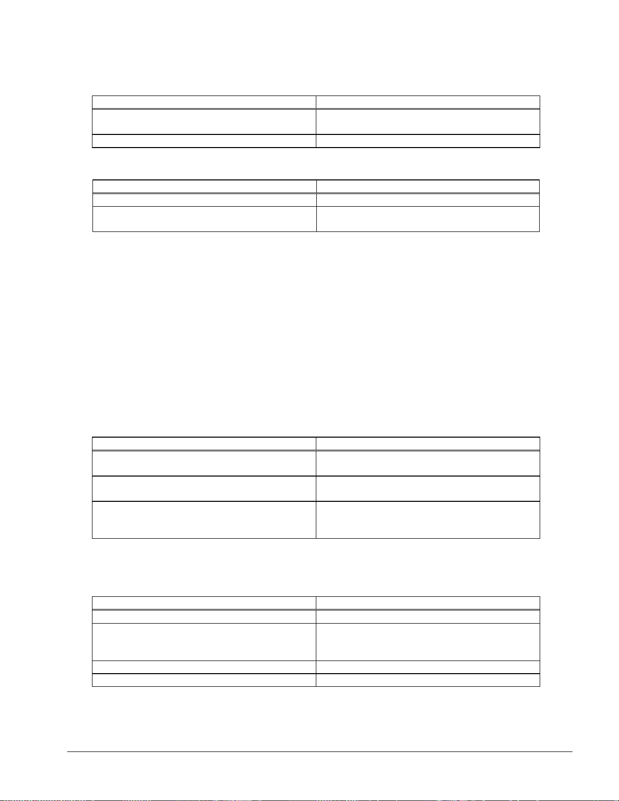
42
TRAK Machine Tools
Southwestern Industries, Inc.
TRAK TRL Lathe, ProtoTRAK RLX CNC Safety, Installation, Maintenance, Service & Parts List
3.2.4.1 Every Part Has the Same Error
Possible Cause
Check This
Programming Error
Programmed dimensions not correct. Check
absolute and incremental values.
Machine & Setup Related
See Machine Tool & Setup - 4.1
Possible Cause
Check This
Machining Setup
See Machine Tool & Setup - 4.1
Looseness in the Drive Train, ball nut loose in
yoke, split nut loose, yoke loose
See Mechanical Drive Train (X, Z) - 4.2
Possible Cause
Check This
Looseness in the Gib
Gib adjustment
See Gib Adjustment - Section 5.2.1
Looseness in the drive train
The drive train Diagnostics
See Mechanical Drive Train (X, Z) - Section 4.2
Failure of the spindle encoder
Run service code 133 to check if the encoder
counts.
Replace spindle encoder
See Spindle Encoder replacement - Section
5.1.9
Possible Cause
Check This
Spindle speed too fast
Slow down spindle speed.
Failure of the spindle encoder
Run service code 133 to check if the encoder
counts.
Replace spindle encoder
See Spindle Encoder replacement - Section
5.1.9
Broken or slipping encoder coupling
Check and replace as necessary
Broken or loose belt on 1630HSRX lathe only
Check belt tension
3.2.4.2 Errors are Random or Accumulate in Size over the Part Run
3.2.5 Threading Problems
Threads can be cut with and an unlimited number of pitches and up to 10 leads.
To reduce the relief area when threading up to a shoulder the spindle speed should be reduced as much
as possible. The slower the speed of the spindle, the closer the cutting tool can come to the end of the
programmed thread before it pulls out and retracts. If a nut must be turned all the way up to a
shoulder, machine a relief area behind the last thread.
NOTE: No machine can thread up to a shoulder and instantaneously pull out.
Perform the following service code and procedure:
Code 133 Spindle encoder test
3.2.5.1 Cross Threading
Threaded parts are cross-threaded after completion of the threading event.
3.2.5.2 Not Threading
The machine will not cut a thread at all.
3.3 Problems Regarding the Motion of the Machine
Page 49
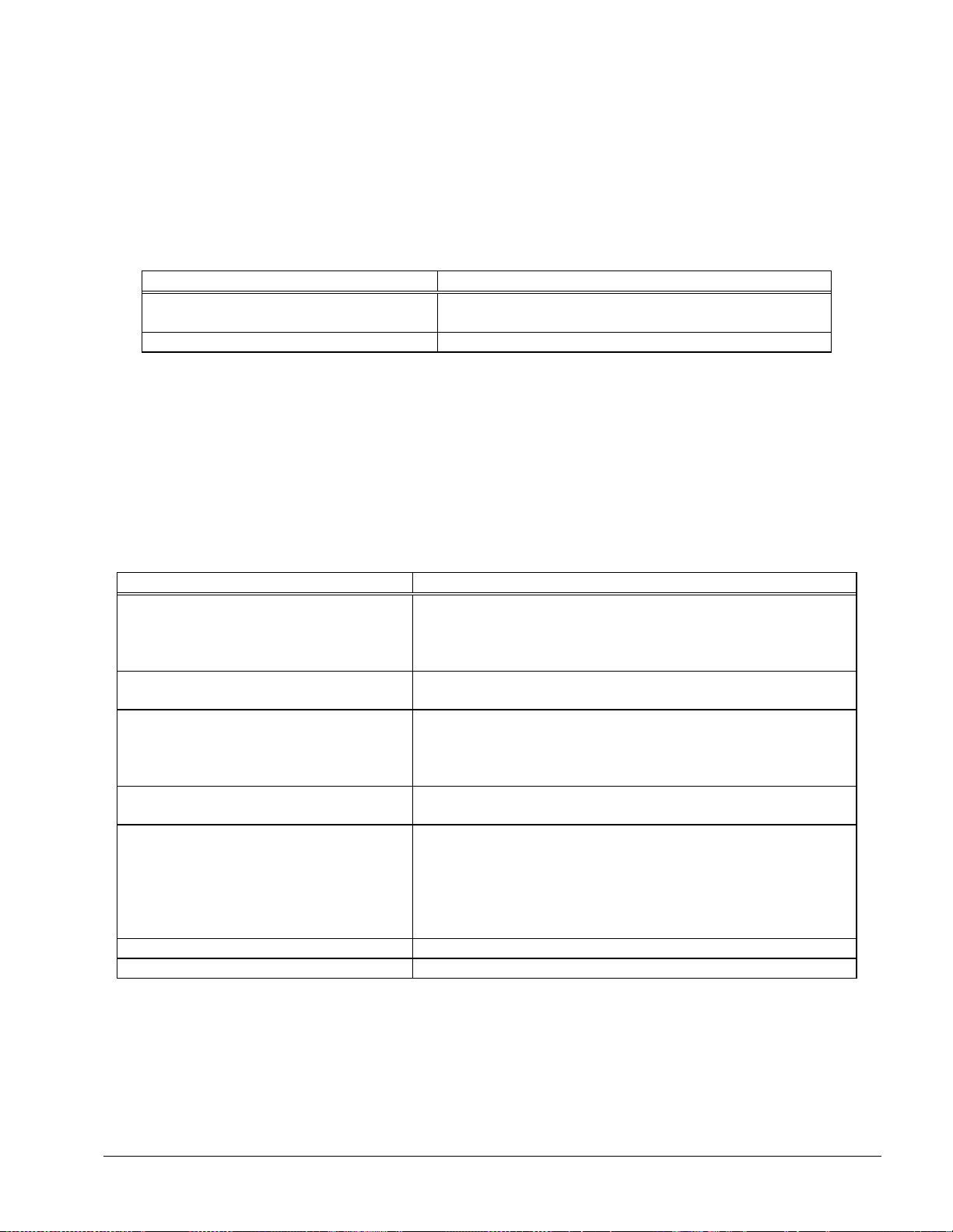
43
TRAK Machine Tools
Southwestern Industries, Inc.
TRAK TRL Lathe, ProtoTRAK RLX CNC Safety, Installation, Maintenance, Service & Parts List
3.3.1 Run Away Axis
Possible Cause
Check This
The home position or tools are not set
correctly
See the Controls Programming, Operations and Care
manual.
Bad Motor Encoder
See Motor diagnostics Section 4.4
Possible Cause
Check This
The maximum allowable Arc Accuracy is
set too low.
This value will only slow down the machine during arc moves.
The factory default is set at 0.005". Perform Code 129 to
check or change this value. See Service Codes section.
Values lower than 0.005” may reduce the feedrate.
Incoming AC voltage is inadequate
Perform Code 100. See Service Codes - Section 4.8 and
Electrical Section 4.6
Inadequate or no Lubrication to
Ballscrews and Way surfaces
Make sure all the Way surfaces are getting proper lubrication.
If not, check to make sure that the lube pump is functioning
properly. Also check for any pinched or blocked oil lines. See
Lubrication Section 4.1.3
X and Z-axis Gibs are not adjusted
properly
Check the adjustment of the X and Z-axis Gibs using the X
and Z-axis Gib adjustment procedures.
Binding in the Drive Train
Check Repeatability using the Repeatability and Positional
Accuracy procedure. Check the torque reading of the Drive
Train. Step by step, carefully inspect the Drive Train for any
binding. It may be necessary to disassemble and then
reassemble the Drive Train. See Mechanical Drive Train (X, Z)
Section 4.2
Servo Drive failure
See Servo Drive Section 4.5
Motor failure
See Motor Section 4.4
The axis makes an unwanted move at rapid speed in one direction and faults out. This is usually
caused by an encoder signal being interrupted.
Perform the following Service Codes:
Code 33 Software Identification. This is needed if you call SWI Customer Service.
Code 131 Manual DRO. Used to move the axes to verify the encoders are counting.
3.3.2 Slow Down Axis
The axis slows down and moves at a feedrate that is lower than rapid or than the programmed
feedrate.
Perform the following Service Codes:
Code 33 Software Identification. This is needed if you call SWI Customer Service.
Code 131 Used to check the maximum feedrate of an axis and if the encoders are counting.
Code 129 Set's the maximum allowable arc accuracy error. This applies to arcs only.
3.3.3 Axis Motor Motion Is Not Smooth
While under motor power, the motion is not smooth. The motion appears to be "rough" or jerky”.
Perform the following Service Codes and procedures:
Page 50
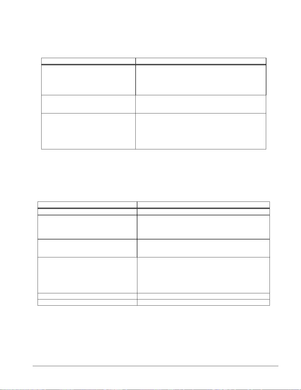
44
TRAK Machine Tools
Southwestern Industries, Inc.
TRAK TRL Lathe, ProtoTRAK RLX CNC Safety, Installation, Maintenance, Service & Parts List
Code 33 Software Identification. This is needed if you call SWI Customer Service.
Possible Cause
Check This
X and Z-axis Gibs are not adjusted
properly
Check the adjustment of the X and Z-axis Gibs using the
X and Z-axis Gib adjustment procedures. Ensure the
belts are not overtightened. Any abnormal sound from
the belts is an indication of misalignment or misadjustment.
Calibration or Backlash problem
Recalibrate the machine. Reset the Backlash. Check
Repeatability and Positional Accuracy. See Calibration &
Backlash Constants section.
Binding in the Drive Train
Check Repeatability using the Repeatability and Positional
Accuracy procedure. Check the torque reading of the
Drive Train. Step by step, carefully inspect the Drive
Train for any binding. It may be necessary to
disassemble and then reassemble the Drive Train. See
Mechanical Drive Train (X, Z) Section 4.2
Possible Cause
Check This
Too much backlash entered in Code 128.
Recheck the machines backlash.
Inadequate or no Lubrication to Ballscrews
and Way surfaces
Make sure all the Way surfaces are getting proper
lubrication. If not, check to make sure that the lube pump
is functioning properly. Also check for any pinched or
blocked oil lines. See Lubrication section
X Gib is not making good contact.
Pull gibs out and mark with a blue die to check where the
gibs are making contact. It is recommended that the gibs
uniformly contact at least 80% of the surface.
Binding or looseness in the Drive Train
Check Repeatability using the Repeatability and Positional
Accuracy procedure. Check the torque reading of the
Drive Train. Step by step, carefully inspect the Drive Train
for any binding or looseness. It may be necessary to
disassemble and then reassemble the Drive Train. See
Mechanical Drive Train (X, Z) Section 4.2
Axis Motor belt too tight.
Loosen belt.
Misalignment of ball screw
See Mechanical Drive Train (X, Z) Section 4.2
Code 127 Measure's the backlash in the system.
Code 128 Enter backlash compensation.
3.3.4 Vibration in Motion
While axis is moving there is vibration or noise coming from the X or Z-axis.
Perform the following Service Codes and procedures:
Code 127 Measure's the backlash in the system.
Code 128 Enter backlash compensation.
3.4 Problem with the Measurements
Page 51
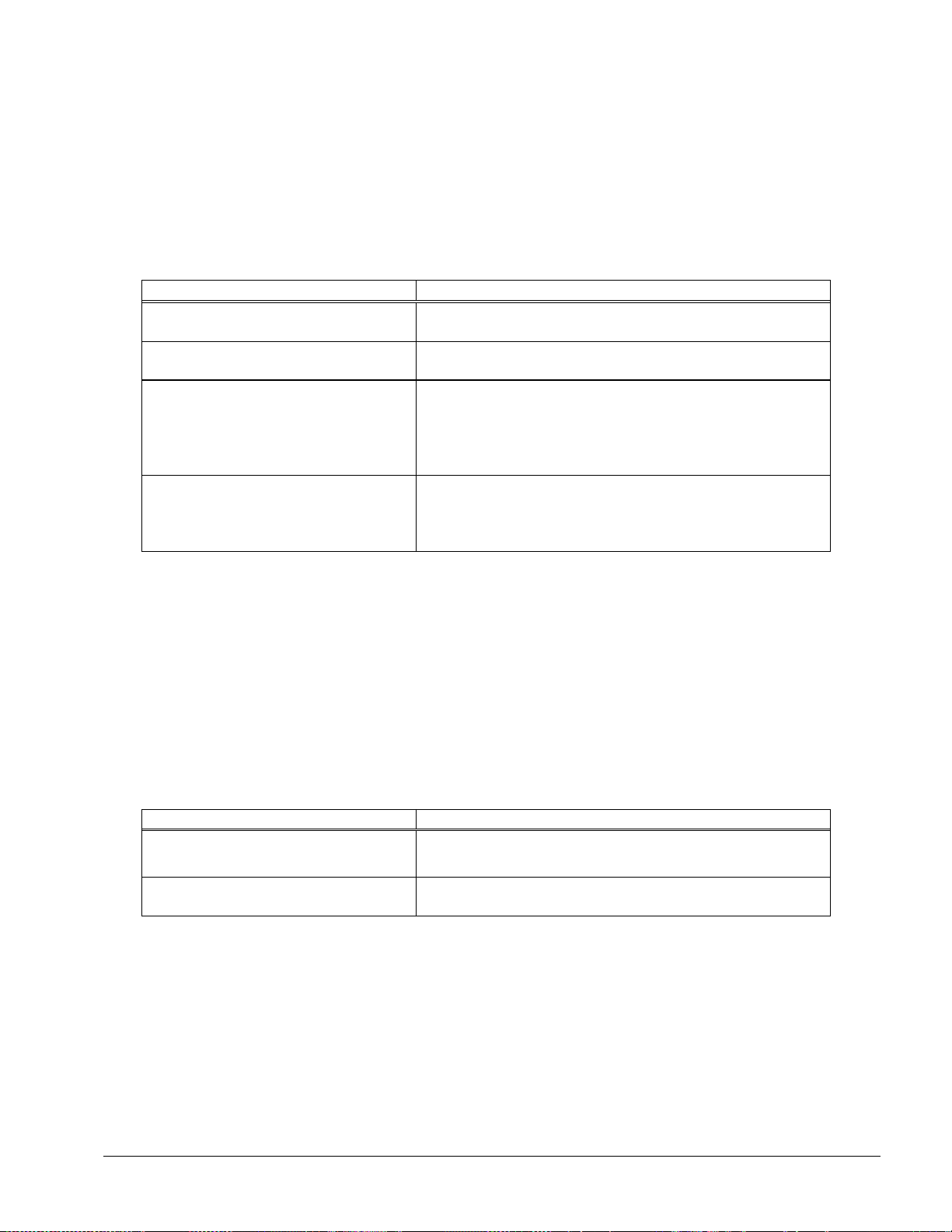
45
TRAK Machine Tools
Southwestern Industries, Inc.
TRAK TRL Lathe, ProtoTRAK RLX CNC Safety, Installation, Maintenance, Service & Parts List
3.4.1 X & Z-Axis Measurements Do Not Repeat
Possible Cause
Check This
Machine Tool & Setup problem
Check for any looseness in the setup. See Machine Tool
& Setup Section 4.1
X and Z-axis Gibs are loose
Check the adjustment of the X and Z-axis Gibs using the
X and Z-axis Gib adjustment procedures.
X and Z-axis Drive Trains are loose
Check Repeatability using the Repeatability and Positional
Accuracy procedure. Step by step, carefully inspect the
Drive Train for any looseness. It may be necessary to
disassemble and then reassemble the Drive Train. See
Mechanical Drive Train (X, Z) Section 4.2
Encoder Disk or Reader Head on
motor are loose
Swap the motor in question with a known good motor. If
the symptom stays with the motor in question, then
replace the motor. If not, then the motor is not at fault
and something else is causing the problem.
Possible Cause
Do This
The Calibration is incorrect
Recalibrate the machine.
See Calibration & Backlash Constants
Incorrect backlash values
If the machine does not repeat bi-directionally check the
backlash on the axis in question. See Section 5.2.2.
With a dial indicator mounted to the spindle, touch off a fixed surface either in the X or Z-axis
direction and then set the DRO equal to 0. Crank away several inches and then touch off again at
the same place. If the reading has not returned to 0 on the DRO, zero the display and repeat the
procedure. If the measurement does not repeat, you have a repeatability problem that must be
resolved.
Expected repeatability numbers should be 0.0005” or less.
3.4.2 X & Z-Axis Measurements Are Not Accurate
Measurements repeat, but with a dial indicator mounted to the spindle, traversing the length of a
gage block or some other measurement standard, the measurement is not accurate.
Note: If your part has incorrect dimensions, see Parts Have Incorrect Dimensions, Section 3.1.4.
Note: First check for repeatability of the DRO: With a dial indicator touch off a fixed surface either
in the X or Z-axis direction and set the DRO equal to 0. Crank away several inches and touch off
again at the same place. If the reading has not returned to 0 on the DRO, zero the display and
repeat the procedure. If the measurement does not repeat, you have a repeatability problem that
must be resolved before the accuracy problem can be resolved. See Measurements That Do Not
Repeat, Section 3.4.1.
Page 52

46
TRAK Machine Tools
Southwestern Industries, Inc.
TRAK TRL Lathe, ProtoTRAK RLX CNC Safety, Installation, Maintenance, Service & Parts List
3.4.3 The DRO Is Not Counting
Possible Cause
Check This
Electronic handwheel failure
Each handwheel should count 0.100” & 0.020” respectively for Z
and X in fine mode, and count 0.400” & 0.100” in course mode.
Servo driver failure
Check the LED status on the axis in question. See Servo driver
Section 4.5
Motor Encoder not counting
See Motor diagnostics
Computer/Pendant failure
See Computer/Pendant diagnostics
The DRO for one axis is not counting when an axis is moved. Often times if this is the case the axis
will fault. See Section 4.4.3.
Perform the following Service Codes:
Code 33 Software Identification. This is needed if you call SWI Customer Service.
Code 132 Electronic handwheel test.
Code 131 Manual DRO test.
3.4.4 X & Z-Axis DRO Counting in Wrong Direction
The DRO is counting in the wrong direction.
The positive directions for each axis are:
X-axis – cross slide moves toward the operator.
Z-axis – carriage moves toward tailstock.
Perform the following service codes and procedures:
Code 33 Software Identification. This is needed if you call SWI Customer Service.
If the product does not match the machine then the machine ID key will need to be replaced.
3.4.5 X & Z-Axis Electric Handwheels Count in Wrong Direction
The Electric Handwheels count in the wrong direction.
The positive directions for each Electric Handwheel are:
X-axis - Electric Handwheel turns counterclockwise
Z-axis - Electric Handwheel turns clockwise
Perform the following service codes and procedures:
Code 308 Reverse X-axis Handwheel Direction
Page 53

47
TRAK Machine Tools
Southwestern Industries, Inc.
TRAK TRL Lathe, ProtoTRAK RLX CNC Safety, Installation, Maintenance, Service & Parts List
3.5 Problems with the Machine Tool
Possible Cause
Check This
Machine Tool and Setup problem
Check the type of material being cut, type and size of cutting tool,
RPM, and Feed rate. Also check the condition of the cutter to verify
that the cutter is not dull. See Machine Tool & Setup Section 4.1
Motor drive Belt is slipping
Check the alignment, condition, and tension of the Drive Belt.
Cut more than the machine is capable
Check speeds, feeds and depth of cut
Spindle Drive Thermal Overload Relay
has tripped
IOUT - Current Out (located on the Spindle Drive). When the Overload
Relay is enabled, an "oL1" error occurs shutting off the Spindle Drive.
The harder the Spindle Motor works trying to make heavy cuts, the
more current the Spindle Motor utilizes. This can be caused by a cut so
large that it exceeds the machine capability, or a problem with the
spindle motor or AC drive.
Spindle Drive parameters are not
correct
May need to re-download the Spindle Drive parameters. Contact
Customer Service for assistance.
Possible Cause
Check This
Wrong voltage
Check the 208V voltage to the machine
Poor wiring connections
Check all the wiring connections to the electric’s box.
Defective cable connections
Check all cable connections
Spindle Motor is bad
Check the resistance of the Spindle Motor windings on the Spindle
Motor between L1 & L2, L2 & L3, and L1 & L3, using an Ohmmeter.
The resistance should range from ".7 to 1.8 Ohm". If the Ohmmeter
reads "0 Ohms" or "OL", then replace Spindle Motor. Next, check the
resistance between L1 & Ground, L2 & Ground, and L3 & Ground,
using an Ohmmeter. The resistance should read "OL". If not then
replace Spindle Motor.
Possible Cause
Check This
3-Phase wires backwards
Need to switch any 2 of the 3 wires either coming out of the
Spindle Drive (T1, T2, and T3) or going into the Spindle Motor (U,
V, and W). Caution: Be sure to shut off all power to the machine
before attempting to switch any wires.
3.5.1 Spindle Stalls or Turns-Off During Machining
During machining, the spindle turns off and loses power. First check incoming voltage and
connections.
3.5.2 Spindle Motor Hums or Will Not Run
The spindle motor makes a constant humming noise during operation or will not turn on.
3.5.3 Spindle Runs Backwards
The spindle motor runs in the opposite direction. The spindle should always spin in the counter
clockwise direction as viewed from the tailstock end of the lathe when the forward key on the
pendant is pressed.
Page 54
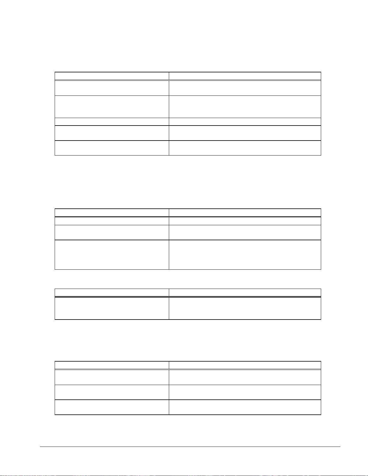
48
TRAK Machine Tools
Southwestern Industries, Inc.
TRAK TRL Lathe, ProtoTRAK RLX CNC Safety, Installation, Maintenance, Service & Parts List
3.5.4 Excess Gearbox Noise
Possible Cause
Check This
Headstock manual oil pump failure
Make sure oil is flowing in the site glass. The oil
pump is run off a gear in the headstock.
Shift level out of position. Gears are not
mating properly.
Move the shift lever in and out. Turn off spindle and
put back in gear. Adjust the gear cluster in question
to make sure it is mating properly.
Lack of lubrication to gear train
Check level of oil in gearbox
Spindle bearing not being lubricated
properly, worn bearing
Check to make sure oil is finding its way to the
bearings.
Spindle preload loose
Tighten spindle preload on bearing. The spindle
preload should be approximately 10-15 in/lbs.
Possible Cause
Check This
Leaking from behind belt drive pulley
Replace shaft seal - o-rings or gaskets.
Oil leaking from behind the spindle
encoder.
Remove spindle encoder and check seal.
Oil leaking from the rear bearing
assembly.
Make sure the rear backing plate is mounted correctly.
There should be a tapped hole located at the 12
o’clock position. If the tapped hole is located at the 6
o’clock position the seal will leak.
Possible Cause
Check This
Oil leaking from seal between lid and
gearbox
Remove gearbox lid and reseal. Thoroughly clean lid
before resealing. Make sure the front backing plate
matches up with the seal behind the cover.
Possible Cause
Check This
Misalignment of tailstock housing
Realign bearing housing and tailstock screw. Loosen
screw support and realign.
Too much grease.
Disassemble and remove excess grease. Add oil to the
tailstock barrel.
Vernier Dial is binding or rubbing on
screw support.
Remove dial and machine off a couple of thousandths
or shim.
Gearbox noise is louder than normal. Take note of the gear where the noise is most noticeable.
Remove the gearbox lid and try to isolate where the noise is coming from.
3.5.5 Headstock is Leaking Oil
A Form-A-Gasket sealant should be use to seal any leaking areas. Make sure the sealant fills the
leaking area thoroughly. Sealant must cure for 24 hours for best results.
3.5.5.1 Leaking Oil from Rear of Gearbox
3.5.5.2 Leaking Oil From Front of Gearbox
3.5.6 Tailstock Barrel is Stiff
The tailstock barrel is stiff or not smooth moving through its travel. The tailstock barrel
subassembly jams inside the tailstock
Page 55

49
TRAK Machine Tools
Southwestern Industries, Inc.
TRAK TRL Lathe, ProtoTRAK RLX CNC Safety, Installation, Maintenance, Service & Parts List
4.0 Diagnostics
Problems With
Can Contribute To:
This section explains the diagnostic procedures used to isolate service problems.
4.1 The Machine Tool & Set-Up
4.1.1 Leveling
Leveling is one of the most important aspects of setting up the machine properly. Improper leveling
can lead to a variety of machining problems.
The machine should be level to within .0008” longitudinally and .0005” transversely. See Leveling
Procedures, Section 2.9.
4.1.2 A Special Word About the X & Z Gib
The X gib is vital to the performance of your lathe.
Gibs should be:
flat
free of twist
free of burrs
free of blockages in the oil passages and channels
Defective or scarred gibs must be replaced. Shimming of gibs will not yield acceptable results.
It is good machining practice to avoid the use of shop air to clean the chips off a machine. This
risks blowing chips into the sliding way surfaces and compromising the performance of the machine.
The Z gib is used to keep the carriage firmly planted down to the ways. There are two Z gibs, one
located on each way.
See Gib Adjustments, Section 5.2.1.
4.1.3 Lubrication
Lubrication is one of the single, most important maintenance issues and plays a key role in assuring
the performance and durability of the lathe. At the beginning of each day manually supply oil to the
way surfaces by doing Service Code 300.
Lack of lubrication can lead to a variety of problems with your machine motion due to increased
friction in the sliding ways. This increased friction may lead to part inaccuracies and decreased life
expectancies of your ball screws and way surfaces.
Make sure the oil pump for the headstock is working properly at the start of each day. Check
periodically the site glass for the headstock oil. The site glass is located under the spindle cover or
under the shift lever on the nameplate. Lack of lubrication in the headstock can lead to increased
wear of the gear train as well as premature wearing or failure of the spindle bearings. For the 1630,
1845 and 2470 oil flows to the site glass only when the spindle is on. For the 1845 oil should be
flowing to the site glass whenever the 208-volt power is on. Not applicable to the 1630HS.
4.1.4 Machining Set-Up
The machining set-up itself is always something that can greatly influence the performance of the
lathe. The following are some things to keep in mind.
Page 56

50
TRAK Machine Tools
Southwestern Industries, Inc.
TRAK TRL Lathe, ProtoTRAK RLX CNC Safety, Installation, Maintenance, Service & Parts List
Feed and Speeds (spindle rpm)
See below
Poor finish
Excessive speeds and feeds can break cutting tools
or wear out too fast.
Tooling
Using the wrong cutter for an application
Poor finish
Parts incorrect
Cutting too deep
Part dimensions incorrect
Driving and cutting forces cause deflections, since no
material is totally rigid
No coolant
Poor finish, decrease the life of the cutter
Problem
Check or Try This
Poor surface finish
Dull tool
Reduce feedrate
Increase spindle speed
Use a higher rake angle tool
Make sure tool is not dull or chipped
Use proper grade of cutting tool
Use coolant
Check to see if tools are on the centerline
Long workpieces out of round
Use a follow or steady rest
Workpiece out of taper
Check headstock alignment
Excessive chatter
Tool bit improperly ground or not on center
Avoid extreme negative rake inserts
Tool overhang too great, tool deflection
Improper feeds and speeds
X gib loose. See
Gib Adjustment,
Section 5.2.1.
Work improperly supported
Machine tool out of level - See
Leveling Procedures,
Section 2.9.
The following is a list of common machining problems and some possible solutions.
4.1.4.1 Spindle Speeds
Spindle speeds are influenced by a number of variables:
Material
Rigidity of the Machine Setup
Coolant
Insert, geometry and material of insert
Depth of cut
4.1.4.2 Feedrates
Factors that affect feedrates:
Depth of cut
Design or type of insert
Sharpness of the insert
Workpiece material
Type of finish or accuracy required
Page 57

51
TRAK Machine Tools
Southwestern Industries, Inc.
TRAK TRL Lathe, ProtoTRAK RLX CNC Safety, Installation, Maintenance, Service & Parts List
4.2 The Mechanical Drive Train (X,Z)
CAUTION!
Unlike a leadscrew, do not unscrew the ball screw from its nut. This will destroy the
ball screw!
Potential Problem:
Check By:
Bad ball screw
Visual inspection of the ball nut - if the nylon seal is broken or deformed, if
contamination has visibly entered the ball nut or if balls are out of the ball nut,
replace the ball screw.
Cranking the ball screw through a significant part of its travel. If it jams, feel loose or
has rough spots, replace the ball screw.
Dial indicator on a vertical flat of the ball screw indicates backlash between the ball
screw and ball nut.
Ball nut not
tightened to the
Inspection for space between the head of the bolt and the ball nut i.e. the retaining
bolt has bottomed out in its thread and is not securing the ball nut to the yoke
Indications:
Troubleshooting instructions indicate that the drive train is potentially the problem and other, more
easily checked, variables have been exhausted.
Roughness, looseness, tightness or jamming movement in the carriage or cross slide.
Carriage walk-up due to Z ball screw misalignment.
1. Check for machine considerations, especially X gib adjustments and leveling. See Gib Adjustments,
Section 5.2.1.
2. The torque required to manual turn the X and Z-axis ballscrews should be between 10 to 15 in-lbs.
These values should be consistent in both directions and along all areas of the axis travel. Values that
differ from that of above may correspond to misaligned ball screws.
The following steps take you in logical sequence through the assemblies. If the step doesn’t isolate or
resolve the problem, it will be necessary to disassemble the indicated item and move to the next step.
See Figures 17 through 22 in Section 5.0. The drawings for the 1845 can be found in the rear of the
manual.
1. Ensure that the screws that hold the bearing housing in place are not loose.
2. Ensure that the Clamp Nut is secured. The following applies to the clamp nut: When loosening, make
sure to back out the 10-32 screw from the clamp nut.
3. When tightening, drag the 10-32 screw to keep the clamp nut from spreading, tighten it again after the
clamp nut is tight. Torque the 10-32 screw to 90 in-lbs. Torque the clamp nut to 50 ft-lbs.
4. Take out the angular contact bearings in the X & Z-axis and inspect them. They should roll smoothly
and be lightly greased. If not, replace them. The Z-axis has 2 bearing housings. One housing is on the
drive train side with the other on the support housing.
NOTE: The bearing housing and spacer rings are matched sets - keep them together.
1. With the motor and drives removed, inspect the ball screw, ball nut and yoke for the potential problems
shown in the chart below.
Page 58

52
TRAK Machine Tools
Southwestern Industries, Inc.
TRAK TRL Lathe, ProtoTRAK RLX CNC Safety, Installation, Maintenance, Service & Parts List
yoke
properly.
Yoke loose in the
carriage
Inspection for any motion of the yoke or looseness in the Yoke mounting screws.
Oil lines sheared
Visual inspection.
Oil line blockage
Pump the oil and ensure that it flows evenly to the ways, ball screws and cross-slide.
Z Ball screws not
aligned properly
Manually turn the ball screw through the length of its travel. Pay particular attention
to the movement near the headstock, the middle and the tailstock.
NOTE: Ball screws are inspected throughout their entire travel for backlash and consistent torque. A ball
Possible problems
Can lead to
Poor cable connections
There are 2 cable connections on the rear of the
pendant. This is the Ethernet cable and I/O cable
(ends with a DB25 connector). Make sure both cables
are properly fastened on both the Pendant and the
Computer Module
Pendant locks up
On the rear of the Pendant, identify the “Key Press”
LED (third from the top of the right LED group). Press
a numerical key and confirm the LED turns on when
the key is pressed. Turns off when the key is no
longer pressed. This confirms the software is running.
Press the E-stop button and see if lock up clears if not
then do the following:
Turn the pendant off (remove power from the
computer module), wait at least 30 seconds, and
connect power back to the computer module. Check
to see if the malfunction has been remedied.
Low voltage or power problem for the
pendant.
Can cause the system to lock up, RSG to fail and the
flash drive to act abnormally.
Refer to the diagnostic LEDs on the rear of the
Pendant. The three power LEDs (+5VDC, +12VDC
and +24VDC) should be on.
If not, ensure the cables on the rear of the pendant
are securely connected to both the pendant and
computer module. Ensure power is supplied to the
computer module.
Possible problems
Can lead to
Flash drive failure
If the flash drive fails, all programs and machine
screw should be good for millions of inches of travel if installed properly. Do not be too quick to replace a
ball screw if there is insufficient indication that it is bad; this will just be a costly delay to resolving the real
problem.
See:
Z Ball Screw Removal,
X Ball Screw Removal,
Aligning Z Ball Screw,
Section 5.1.14
Section 5.1.12
Section 5.1.15
4.3 Pendant and Computer Module Diagnostics
The following table lists some problems and what these problems can lead to.
Page 59

53
TRAK Machine Tools
Southwestern Industries, Inc.
TRAK TRL Lathe, ProtoTRAK RLX CNC Safety, Installation, Maintenance, Service & Parts List
configurations will be lost. Make sure to back up your
flash drive from time to time. Only the flash drive
module will need to be replaced.
LCD backlight burns out
If the LCD appears to be blank with no light showing,
shine a light onto the LCD. If characters can be seen
on the LCD, the LCD backlight is not functioning.
Faulty E-stop switch
Refer to the diagnostic LEDs on the rear of the
pendant. When the E-Stop is not engaged (ie out), the
“E-STOP1-OUT” LED will be on. Push the E-stop
button in (engaged), the LED will go out.
It can be stuck open or closed (pressed). If it is stuck
closed the pendant will need to be replaced because
the user will have no way to get rid of the message. If
it is open it will allow the machine to still operate but it
will be unsafe for the user. The pendant will still need
to be replaced.
Overlay failure (keys on pendant)
Certain buttons on overlay do not work. Do code 81 to
verify each key beeps.
Page 60

54
TRAK Machine Tools
Southwestern Industries, Inc.
TRAK TRL Lathe, ProtoTRAK RLX CNC Safety, Installation, Maintenance, Service & Parts List
4.4 Motor Diagnostics
WARNING!
Do not work with the motors unless the power is disconnected from the machine.
The motors are run by 208 VAC. There is possibility of death by electrocution!
The Motor subsystem is comprised of 2 parts: The Motor Encoder and the Motor. The motors are blushless
powered by 200 to 240 volt single phase power input. The servo driver is also an integral part of servo
system, which is discussed in the next section.
Rarely do both the X and Z motor/servo systems fail at the same time and in the same way. So, if your problem
is occurring on both axes, its source is probably somewhere else.
4.4.1 Cable Connections
Check the motor cable connections on the cable breakout box and from the servo to motor. Verify there
are no pushed in pins on the connector.
4.5 Servo Drivers
The servo drivers are used to control the motors. They are run on single phase 200 to 240 volt power. The
two (2) servo drivers are located in the electrical cabinet. There are two power sources: one for the control
circuit which powers the LED display and the main terminals used for the power circuit.
The computer module outputs a command to each servo drive via a signal with a voltage which is between 10 and +10 volts. The + and – voltage dictates the motor rotation direction and the magnitude sets the
speed of rotation.
Indications:
Problems moving just one axis. The axis faults out on the screen.
Servo Types:
X is a light duty driver
Z is a heavy duty driver
When the AC servo drive has a fault, the LCD will display “ALnnn”. :AL” indicates the alarm and “nnn”
indicates the drive fault code. The following is a list of the fault codes:
Page 61
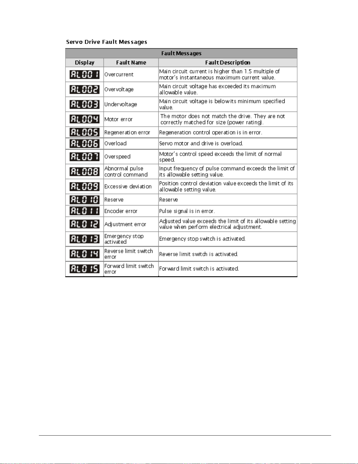
55
TRAK Machine Tools
Southwestern Industries, Inc.
TRAK TRL Lathe, ProtoTRAK RLX CNC Safety, Installation, Maintenance, Service & Parts List
Figure 4.5a Motor Servo Driver Fault Errors
Page 62
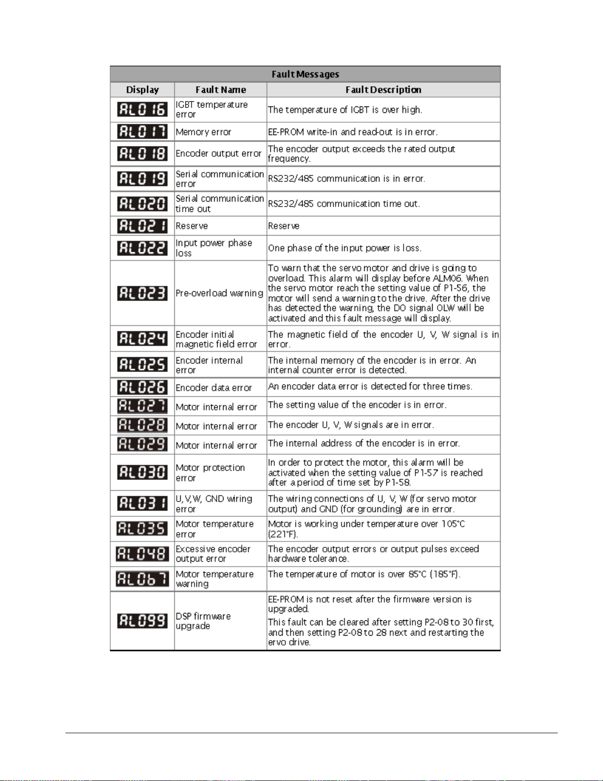
56
TRAK Machine Tools
Southwestern Industries, Inc.
TRAK TRL Lathe, ProtoTRAK RLX CNC Safety, Installation, Maintenance, Service & Parts List
Figure 4.5b Motor Servo Driver Fault Errors
4.6 Electrical
Page 63

57
TRAK Machine Tools
Southwestern Industries, Inc.
TRAK TRL Lathe, ProtoTRAK RLX CNC Safety, Installation, Maintenance, Service & Parts List
For layout and connectivity of the Electrical Cabinets, refer the drawings 29103-x in Section 7.
4.6.1 Checking A/C Voltage
This procedure tests for the 208 VAC for the control. Check the power input to the computer
module.
Use a Voltmeter, reading A/C volts
Acceptable range is 200V to 240V
Note: systems running consistently close to the high or low values may have problems when normal
voltage fluctuations push the voltage out of the acceptable range.
4.6.2 Checking Fuses
To locate the fuses and their sizes, refer to the Electrical Cabinet drawing 29103-x found in Section
7.
To check fuses:
1. Use a Mulitmeter (Volt/Ohmmeter); select “OHM” or “”.
2. Remove the fuse completely from the pendant display or computer module.
3. Place a lead of the meter on each end of the fuse.
A good fuse reads 0 (zero) or close to it.
A bad fuse reads Open or Infinity or OL (overload).
4.6.3 Main Electrical Box
The electrical box is made up of the following main components:
1. AC drive – used to control the spindle motor.
2. Spindle Motor Braking Resistors: 3 braking resistors – used to brake the spindle motor. To
verify the resistors are good, measure the resistance across B1 and B2 of the AC drive. For the
1630, these connected resistors should measure 20 ohms (+-2 ohms). The 1845 and 2470
should read 10 ohms (+- 1 ohm) when the resistors are good. Values lower or higher than this
could be one or both resistors are bad. The 1630 uses (3) 500 watt 60 ohm resistors. The
1845 uses (3) 500 watt 30 ohm resistors. The 2470 uses (3) 1000 watt 30 ohm resistors.
When good your meter should read approximately 10 ohms.
3. Computer Module – see section 4.6.4.
4. Servo drivers – servo drivers for the X and Z-axis motors.
4.6.4 Computer Module Connections
The list below describes what takes place through each connection. Power reaches the AC IN
directly on the Computer Module. From there power is distributed through the system. This power
is used to send power to the Pendant through the I/O cable.
The following is the set of connections for the Computer Module:
Spindle Encoder input – CPC14
2 USB ports – not for users
Com ports – 1 and 2. COM1 for looking at the computer module BIOS and COM2 is a spare.
Page 64

58
TRAK Machine Tools
Southwestern Industries, Inc.
TRAK TRL Lathe, ProtoTRAK RLX CNC Safety, Installation, Maintenance, Service & Parts List
Ethernet connector – master and slave communicate via an Ethernet cable between pendant
and computer module
AC power input – 200 to 240 volt for USA
Machine ID key – DB25
Pendant I/O – DB25 – Carries E stop and run panel buttons back and forth from pendant to
computer module
Handwheel/Jog connector – DB25
Motor and Spindle axis connectors – DB25 – spindle, X, Turret, and Z axis.
14 inputs, the following inputs are all 24VDC
IN-GRD2 – not used on USA, can be used for chuck in future
IN-GRD3 – Door guard
IN-X Limit – X limit switch input
IN-Z Limit – Z limit switch input
IN-AIR PRES – monitors the air pressure of the CNC Turret
IN-GEAR 1 - low gear input - (for example low gear on 1845 and 2470 lathe)
IN-GEAR 2 – monitors gear switch (not used on USA lathe at moment)
IN-GEAR 3 – high gear input (for example high gear on 1845 and 2470 lathe)
IN-GEAR PRESS – monitors oil pressure to spindle (not used on USA machines at
moment)
IN LUBE OIL PRESSURE/LOW – input from lube pump to signal low pressure or low
oil in reservoir (Not Used at this Time)
IN-SPARE 1 and 2 – extra inputs
IN-SPARE 3 and 4 – extra inputs
IN-REMOTE ESTOP – the E stop on the apron on each lathe plugs into here.
IN-TURRET
Clamp – LED on when turret is clamped
Unclamp – LED on when turret is unclamped
Home – LED on when at home or tool postion 1
spare
9 outputs, the following outputs are all 24VDC
OUT-TURRET-INDEX –
OUT GRD LOCK – output to add a door lock (used on Euro only)
OUT-TURRET UNCLMP
Page 65

59
TRAK Machine Tools
Southwestern Industries, Inc.
TRAK TRL Lathe, ProtoTRAK RLX CNC Safety, Installation, Maintenance, Service & Parts List
OUT LUBE PUMP – output to run lube pump. Software controls frequency and
WARNING!
Do not plug and unplug connectors with the system power on. This may cause
damage to the connector board and harm to the technician.
discharge time
OUT COOLANT PUMP – output to run coolant pump
OUT LIGHTS – output to run work lamp
OUT 24DC - Used as part Aux I/O and spare voltage output
OUT SPARE 1 – extra output
OUT SPARE 2 – extra output
4.6.5 Cable Connections
The lathe machines use several cables to communicate between systems. It is often the case that
what appears to be the failure of an electrical component is actually attributable to a poor
connection.
Indications:
Control problems, chronic or intermittent.
Motor problems.
Measurement problems.
Explanation:
1. Turn off and
2. Visually inspect the connections for excessive debris, moisture, or obvious damage.
3. Carefully clean any chips away from the connectors.
4. One-by-one, take out each connector and then plug them back in. Do the same at the
computer/display.
5. Make sure the screws are tightened on each of the connectors.
unplug
the system from the wall.
4.7 Door & Gear
All TRAK lathes use a door interlock switch to verify to the control that the door is closed in various modes of
operation. This switch is wired normally open but is forced closed when the door is closed during CNC run
mode. There should be continuity between pins 1 and 6 when the switch is forced closed and no continuity
when the switch is in the open position. Gear switches in all lathes are electrically the same, however there
exist a difference how they are actuated mechanically.
In 1840SX & 2460SX the gear shifter turns OFF the opposite gear switch, when the 1845SX & 2470SX turns
the corresponding gear switch ON. It is explained below:
Gear Switch – 1845RX & 2470RX
The switches are mounted on the rear of the headstock (see drawing 27945 for 1845) under the sheet metal
belt cover. The switch closest to the headstock casting controls low gear and the other one controls high
gear. In HIGH SPEED handle position high speed switch is released. In LOW SPEED handle position low
speed switch is released. Both switches are wired normally closed. This means the contact is open when the
switch is pushed. If the gear shifter is in the middle of both gears, both switches will be pushed, contacts
will open and the spindle will be in neutral. There should be no continuity between pins 1 and 6 when the
high gear switch is pushed and continuity when the switch is released in “High speed” handle position. There
Page 66

60
TRAK Machine Tools
Southwestern Industries, Inc.
TRAK TRL Lathe, ProtoTRAK RLX CNC Safety, Installation, Maintenance, Service & Parts List
should be no continuity between pins 2 and 7 when the low gear switch is pushed and continuity when the
switch is released in “Low speed” handle position. The spindle control electrical box gear LEDs will indicate
GEAR1 for High Speed and GEAR2 for Low Speed and in neutral position both LEDs will remain OFF.
4.8 Service Codes
Service codes are broken down into the 5 following categories: software, machine setup, diagnostics, user
options/defaults and lubrication pump control.
All Service Codes are accessed in the SET-UP Mode by pressing the soft key for “SERV CODES”. The service
codes can be found under one of the headings listed on the main screen. Press the heading you want to
access the code in question. If you know the code #, press the CODE # softkey and it will take you directly
to the code in question. Press CODE #, enter the number you want, press SET.
4.8.1 Software Codes
The following codes pertain to software functions in the control. To get to any of these codes go to
Service Codes, press “A” and press the code you wish to view.
Note - If you are working with the SWI Customer Service Group, write the values down for Code 33.
These values will be valuable for troubleshooting.
4.8.1.1 CODE 33: Software ID
The Code 33 is the software identification procedure. The two types of software in the control
include:
Software Version - the version of the system you have installed
Firmware Version - the version of firmware software that is responsible for control to servo
interface.
Converter Version – the version of software that is responsible for converters and options.
Operating System Version – shows the version of the XP operating system
4.8.1.2 CODE 141: Load Configuration File to the Computer
This code allows you to load your configuration file from a selected drive to your hard drive. The
configuration file consists of items such as calibration and backlash constants. This code is used
when a computer module or hard drive has been replaced.
4.8.1.3 CODE 142: Save Configuration File from the Computer
This code allows you to save your configuration file to an external thumb drive. The configuration
file consists of items such as calibration and backlash constants. This code is used when a computer
module or hard drive needs to be replaced. This stores the configuration file from the hard drive to
an external thumb drive. It is a good idea to do this code after the machine is initially setup so
these values can be saved and used in the future. If the computer or hard drive fails, then you will
not have the ability to save the configuration file and the machine will need to be re-setup when the
computer or hard drive is replaced.
4.8.1.5 CODE 316: Update Master Software
Load upgrade disk in an external drive and press this service code. New software will automatically
download and control will reboot.
Page 67

61
TRAK Machine Tools
Southwestern Industries, Inc.
TRAK TRL Lathe, ProtoTRAK RLX CNC Safety, Installation, Maintenance, Service & Parts List
4.8.1.6 CODE 317: Update Slave Software
Load upgrade disk in an external thumb drive and press this service code. New software will
automatically download.
4.8.1.7 CODE 318: Activate Converters or Options
See programming and operating manual.
4.8.2 Machine Set-Up Codes
The following codes are used primarily when setting up a new machine. To get to any of these
codes go to Service Codes, press “B” and press the code you wish to view.
4.8.2.3 CODE 123: Calibration
See Section 5.22 for a further explanation of this code.
4.8.2.4 CODE 127 - Set X or Z Backlash Constant
See Section 5.22 for a further explanation of this code.
4.8.2.5 CODE 128: Input Backlash Constant
Code 128 allows you to enter the backlash values for each axis. It displays the value after it enters.
This code is only used on machines with motor encoders only.
4.8.2.6 Code 308: Reverse X Hand Wheel Direction
This service code reverses the direction of the X hand wheel.
4.8.2.8 Code 311: Run Machine with Spindle Off
This service code toggles this function on or off. It defaults to off from the factory, which means
the spindle must be on for a program to run. If it is on and you forget to turn the spindle on, the
tool will move to Z rapid and wait for the spindle to come on. This function will be needed if you are
running a repeatability program with an indicator in the spindle. Make sure this feature is on when
cutting parts.
WARNING!
Use only chucks which are rated to the maximum RPM of the lathe.
4.8.2.9 Code 312: Toggle Limit Switches On/Off
This service code toggles the limit switches on or off. Code 313 also displays which state the limit
switches are in.
4.8.2.10 Code 510: Spindle RPM Calibration
This service code calibrates the spindle using its encoder, simply follow the on screen instructions.
Please note that when installing new machine, or replacing computer module, that if no
configuration is present, spindle may not run properly. Press the F4 button to load spindle
calibration defaults, if needed. This has no effect on other settings such as calibration, backlash,
etc.
Page 68

62
TRAK Machine Tools
Southwestern Industries, Inc.
TRAK TRL Lathe, ProtoTRAK RLX CNC Safety, Installation, Maintenance, Service & Parts List
4.8.3 Diagnostic Codes
The following codes are used primarily when diagnosing a problem with the machine. To get to any
of these codes go to Service Codes, press “C” and press the code you wish to view.
4.8.3.1 Code 1: Program, Configuration File, Log Back up
This service code captures all important data from the RX machine. This includes the users
program, master and slave configuration files, master and slave message logs, master and slave
fault logs etc. This is meant to be used to help solve problems that may pertain to the software.
This file can then be emailed to the SWI service department. The files are saved to a Zip file.
4.8.3.2 Code 54: Program Continuous Run
This Code runs a program continuously without stopping for tool change commands. It is helpful in
running a long period to identify an intermittent problem.
1. Prepare a program as you normally would.
2. Press MODE, SET UP, “C”, Code 54, INC SET. The program run will start automatically.
3. Press STOP to stop, and GO to continue.
4.8.3.3 Code 81: Keyboard Test
This code is used to check if the keyboard is functioning correctly. It allows you to test each key on
the pendant individually. When you press the keys, the corresponding box for that key will highlight
on the screen. The pendant will also beep, indicating that the key is working correctly. If one of
the keys does not work the pendant assembly may need to be replaced. If none of the keys are
working chances are that the computer module will need to be replaced.
4.8.3.4 Code 131: Manual DRO
A manual diagnostic routine to check the motor encoder and table encoders. Turn the X hand wheel
to display the encoder readings. This code will display the actual DRO counts and the raw encoder
counts before the calibration and backlash factors have been factors into the counts.
4.8.3.5 Code 132 - Electronic Hand Wheel Test
Turn the X or Z-axis electronic hand wheel. The display should show movement as the hand wheel
is being turned. There should be no skipping and it should count smoothly while the hand wheel is
being turned. One revolution of hand wheel should read 0.4000” for Z and 0.1000” for X in course,
and 0.100” & 0.020” for fine mode.
4.8.3.6 Code 314: Toggle Test Lights ‘On’ in Status Line
This code toggles on and off 2 test lights that appear in status line. The top light signifies if the
master software is working. If functioning it should flash a green light. The bottom light signifies if
the slave firmware is functioning. It will appear orange in run mode when it is processing
information. Pressing the mode key will change this orange box to black. The orange box will also
change to black when the program you are running reaches the 3rd event from the end of the
program. If the firmware is locked up no keys will work. This code is useful for diagnosing
intermittent problems with the control locking up.
4.8.3.7 Code 319: Error Log
This code when turned on captures the commands that were sent to the servo system. It includes
items such as positioning commands, errors, stop and go commands, etc. It may be helpful for
identifying problems between programmed commands and executed commands. To turn on the
Page 69

63
TRAK Machine Tools
Southwestern Industries, Inc.
TRAK TRL Lathe, ProtoTRAK RLX CNC Safety, Installation, Maintenance, Service & Parts List
error log press the F6 softkey. The page forward and backward keys allow you to scroll through the
file one page at a time. The data forward and data backward keys allow you to scroll through the
file one line at a time. The data bottom key takes you to the bottom of the file and then changes to
data top which will take you back to the top. The file will capture data until the file reaches a size of
approximately 600 KB. At this time the file is saved to a backup file and the original file is cleared
and data is once again captured. Once again as the file reaches a size of 600 KB it copies over the
previous backup file. From here the user can save the file to an external thumb drive by pressing
the F8 softkey. Once this in done it prompts for which file you want to save to disk. The F1 key
saves the current file to disk and the F2 key saves the backup file to disk. To clear the files press
the F7 softkey.
4.8.3.8 Code 326: Look Up Message
Allows user to display safety flashing messages, master messages and slave error messages on
screen. Often used by translators converting English language to some other language.
4.8.3.9 Code 327: Display Memory Check
Displays memory availability of various devices.
4.8.4 Operator Defaults/Options Codes
The following codes allow the user to set programming defaults or turn features on or off. To get
to any of these codes go to Service Codes, press “D” and press the code you wish to view.
4.8.4.1 Code 79: Beeper On
This turns on the beeper to the control keys.
4.8.4.2 Code 80: Beeper Off
This turns off the beeper to the control keys.
4.8.4.3 Code 143: Toggle Tool Change Spindle Mode
This code allows the spindle to stay on at tool changes when turned to the ON position.
4.8.4.4 Code 328: EPA On/Off
Turn the EPA feature on or off
4.8.5 Lube Pump Codes
The following codes are used for programming and operating the lube pump. To get to any of
these codes go to Service Codes, press “E” and press the code you wish to view.
4.8.5.1 Code 300: Lube Pump Switch
This code acts as a switch to turn the lube pump on for the programmed time set in Code 302.
4.8.5.2 Code 301: Set Lube Pump cycle time
This code sets the interval time between lube cycles.
4.8.5.3 Code 302: Set Lube Pump discharge time
This code sets the lube pumps discharge time.
Page 70

64
TRAK Machine Tools
Southwestern Industries, Inc.
TRAK TRL Lathe, ProtoTRAK RLX CNC Safety, Installation, Maintenance, Service & Parts List
5.0 Procedures for Replacements & Maintenance
WARNING!
Do not work with the brushless motors unless the power is disconnected from the
machine. The motors are run by 208 VAC. There is possibility of death by electrocution!
WARNING!
Do not remove the Servo Drives unless the power is disconnected from the machine.
The servo drives are run by 208 VAC. There is possibility of death by electrocution!
DANGER!
Always engage (push in) the Emergency Stop switch, turn the ProtoTRAK RX Control
off, and disconnect the servo motor/driver cable at the cable breakout box.
5.1 Replacements
5.1.1 Brushless Motor Replacement
1. Turn off power to the machine.
2. Each X (750Watts) is mounted by the use of (4) M6-25 cap screws. The Z axis motor (2KW) is
mounted by the use of (4) M8-25 screws. Be careful not to over- tighten these bolts and strip
the threads.
5.1.2 Servo Drive Replacement
The Servo Drive for each axis is mounted in the electrical cabinet using (2) M5-30 cap screws.
1. Press in the Emergency Stop.
2. Remove power from the machine.
3. Disconnect the two digital cables with DB connectors (CN1 and CN2).
4. Disconnect the incoming motor power 8 individual wires with lug termination from the drive
(labelled L1-6, L2-6, L1-7, L2-8, L3-7, U, V, W). Do not pull on the wires.
5. Remove the green ground wire by removing the green screw on the bottom left corner of the
unit.
6. Mount the new servo drive in the cabinet. The servo drive is programmed for either X or Z axis.
7. Reconnect the green ground wire followed by the two digital cables and 8 power wires.
Page 71
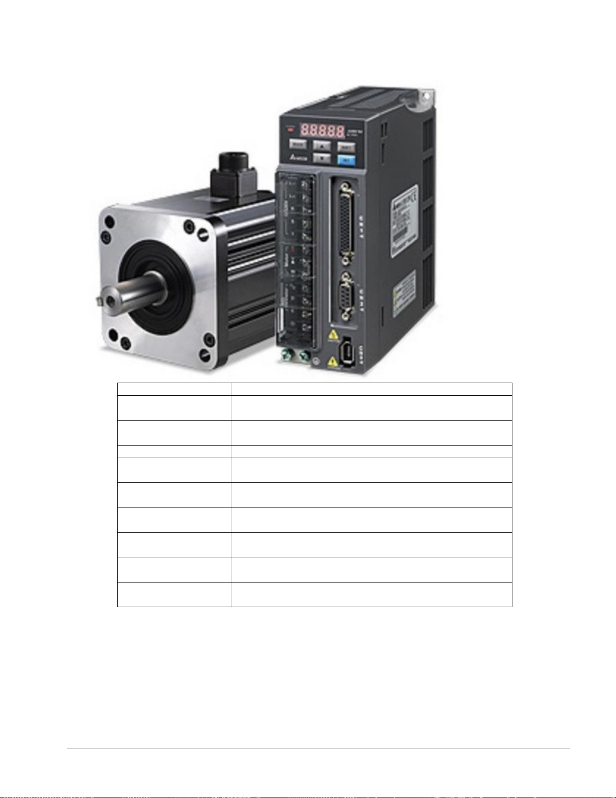
65
TRAK Machine Tools
Southwestern Industries, Inc.
TRAK TRL Lathe, ProtoTRAK RLX CNC Safety, Installation, Maintenance, Service & Parts List
P/N
Description
28164
Motor-Brushless-Delta-750W
(1630RX/1630HSRX/1845RX/2470RX: X Axis)
28164-2
Motor-Brushless-Delta-2KW (1630RX/1630HSRX/1845RX Z
Axis)
28164-3
Motor-Brushless-Delta-2KW (2470RX Z-Axis)
29980-1630US-X
1630RX X-Axis Servo Drive – Delta – Programmed – RX750W
29980-1630US-Z
1630RX/1630HSRX Z-Axis Servo Drive – Delta –
Programmed – RX-2KW
29980-1845-X
1845RX X-Axis Servo Drive – Delta – Programmed – RX750W
29980-1845-Z
1845RX Z-Axis Servo Drive – Delta – Programmed – RX2KW
29980-2470RX-X
2470RX X-Axis Servo Drive – Delta – Programmed – RX750W
29980-2470RX-Z
2470RX Z-Axis Servo Drive – Delta – Programmed – RX2KW
Figure 5.1.2 - Servo Drive and Motor Replacement & Part List
5.1.3 Pendant and Computer Module Replacement
5.1.3.1 Pendant Replacement
1. Turn power off to the machine and control.
Page 72
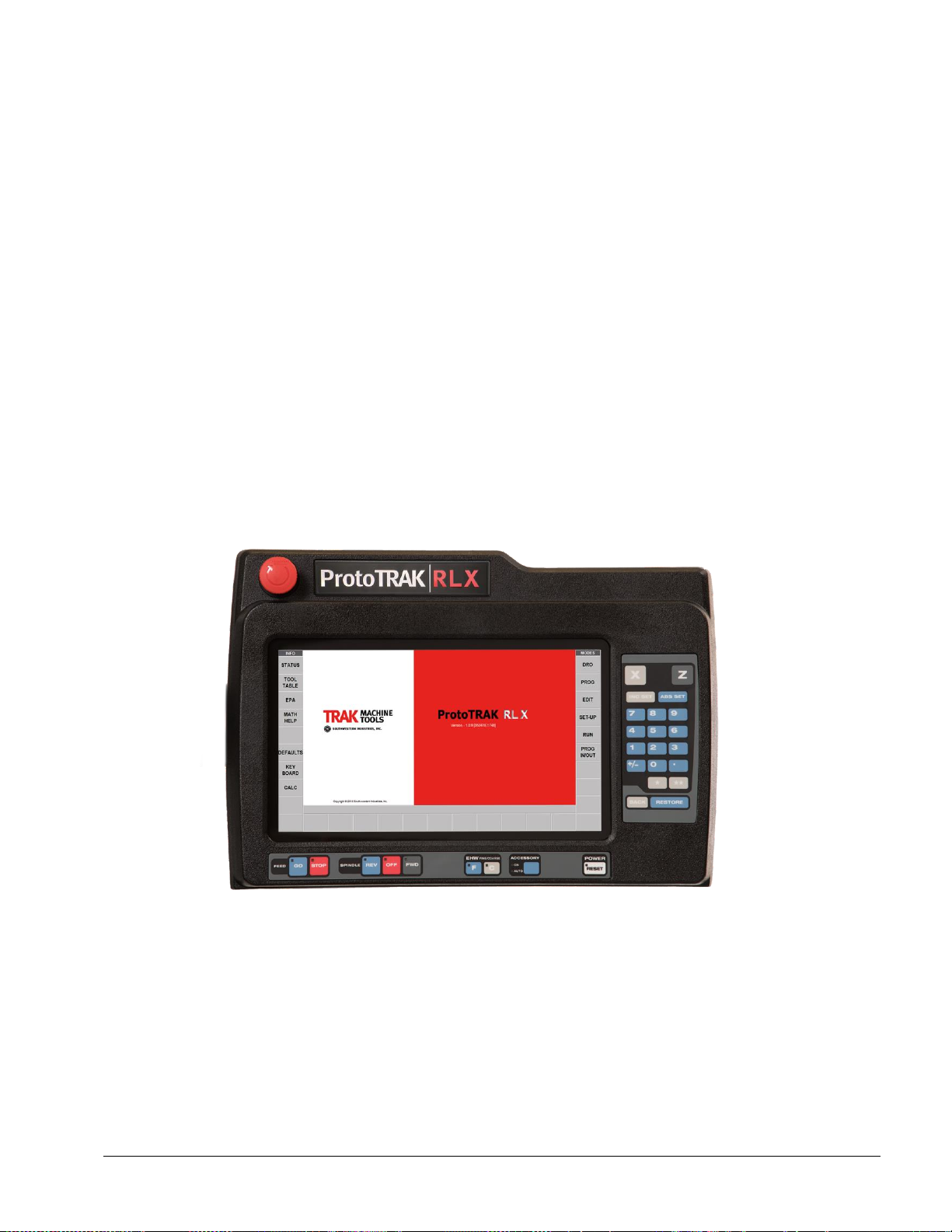
66
TRAK Machine Tools
Southwestern Industries, Inc.
TRAK TRL Lathe, ProtoTRAK RLX CNC Safety, Installation, Maintenance, Service & Parts List
2. Unplug all the connectors on the back side of the pendant.
3. Remove the pendant from the pendant arm by removing the (4) M6-1.0x25 25B screws that
secure it in place.
4. Mount the replacement pendant on the arm with the (4) mounting screws.
5. Reconnect all the previously removed cable connections.
5.1.3.2 Computer Module Replacement
1. Turn power off to the machine and control.
2. Unplug all the connectors connected to the Computer Module.
3. Remove the Computer Module from the Electric Box by removing the (6) M5-0.8x12 SHCS that
secure it in place.
4. Replace the Computer Module and reinstall by mounting with the screws used to mount the
previous unit.
5. Reconnect all the previously removed cable connections.
Figure 5.1.3.2 - Pendant & Computer Module Replacement
Page 73
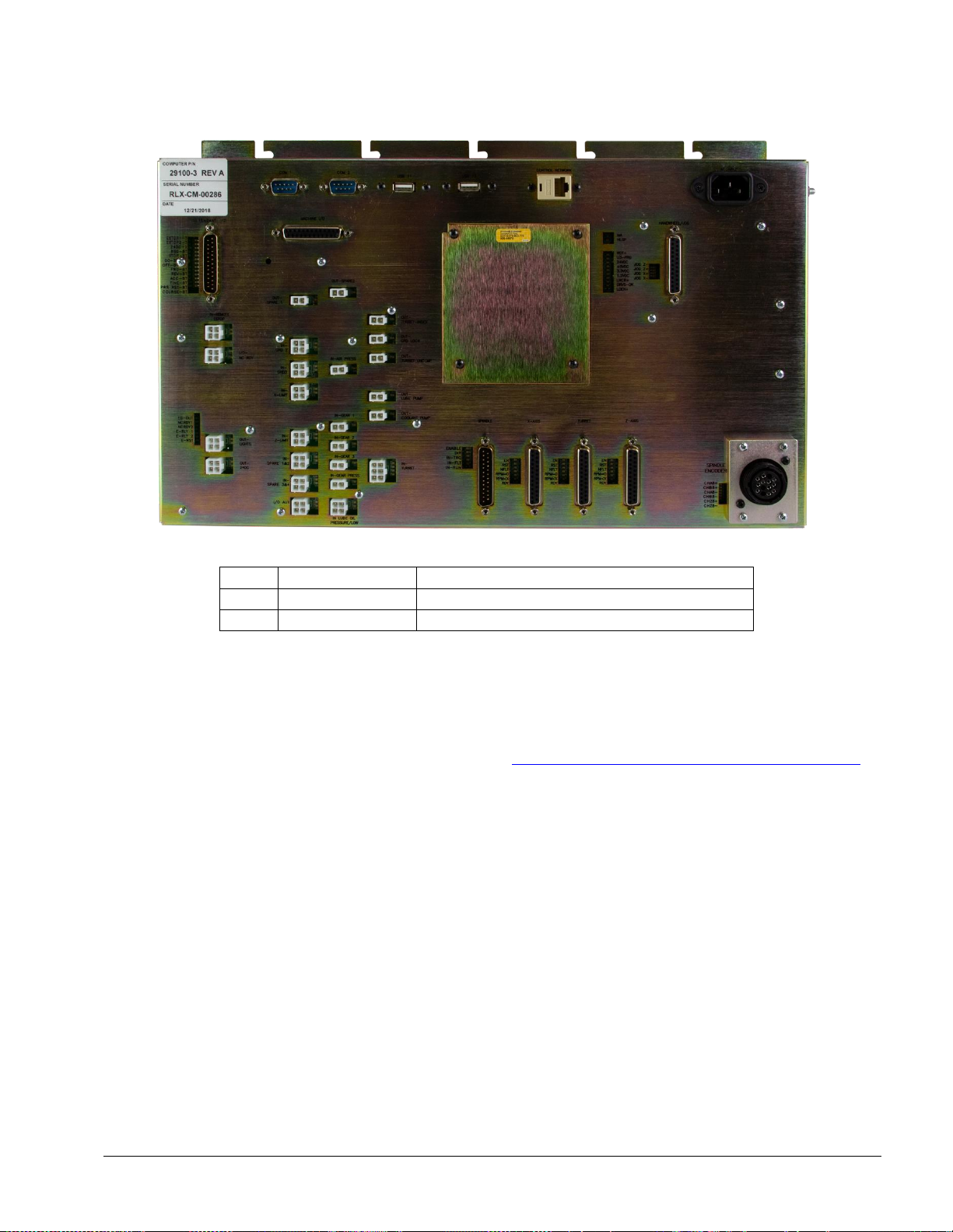
67
TRAK Machine Tools
Southwestern Industries, Inc.
TRAK TRL Lathe, ProtoTRAK RLX CNC Safety, Installation, Maintenance, Service & Parts List
Item
P/N
Description
1
29006-2
RLX PENDANT
2
29100-3
RLX COMPUTER MODULE
Figure 5.1.3.2 - Pendant & Computer Module Replacement
5.1.4 Updating the Pendant and Computer Module Software
1. On the pendant, touch the “Status” soft key on the upper left portion of the touch screen. This
will display the pendant and CM software version.
2. To verify the current software versions, go to https://www.southwesternindustries.com/software
Click on the “Current ProtoTRAK CNCs Software” tag. Find the RX section and refer to the
software versions list.
3. To update to a more current version, first download the software from the website onto a USB
Flash Drive.
4. Plug the USB Flash Drive into one of the pendant USB ports.
5. On the Pendant, select the soft key “Service Codes”. Type in “316” and press the ABS Set
key. Follow the instructions on the screen.
NOTE: Your configuration/calibration settings will not be changed by this procedure.
If you wish to store your settings on a USB Flash drive, install a drive in one of the ports and use
Service Code 142 to save the values. Service Code 141 can be used to restore the values on your
Flash Drive back onto the pendant.
5.1.5 Cable Routing on Machine & In Electrical Cabinet
Whenever you replace a cable or reroute a cable it is very important to keep the power cables and
logic cables separated from each other. The power cables consist of the (2) 208-volt motor cables
Page 74
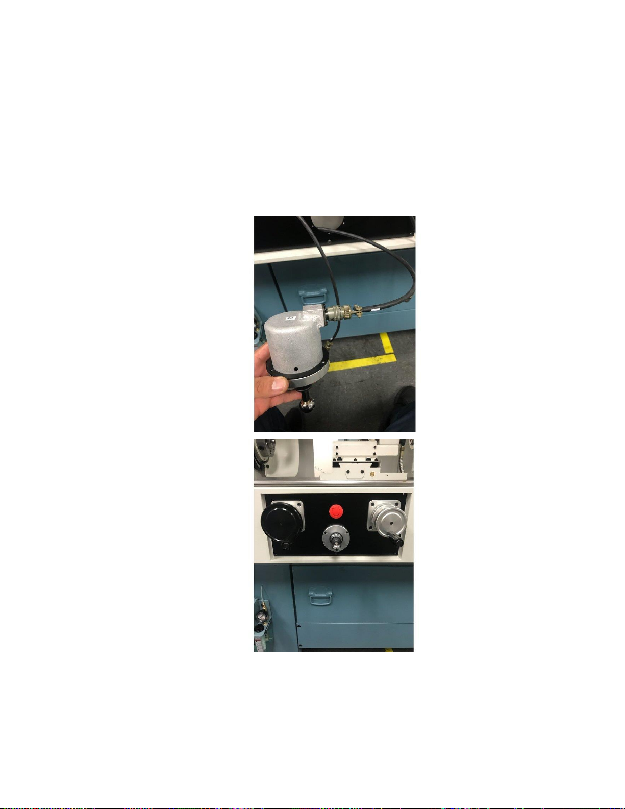
68
TRAK Machine Tools
Southwestern Industries, Inc.
TRAK TRL Lathe, ProtoTRAK RLX CNC Safety, Installation, Maintenance, Service & Parts List
and (2) 208-volt power cables for the Computer Module and a coolant pump or lube pump cable.
The logic cables are used to carry encoder signals between the servos and computer module.
Mixing of the power and logic cables may cause noise from the power cables to interrupt the signals
in the logic cables. This can lead to intermittent axis faults or repeatability problems.
5.1.6 Electronic Handwheels & Jogstick
There are 2 electronic handwheels on the lathes and 1 jogstick to move the carriage quickly into
position. Each unit is replaced as an assembly. Disconnect the handwheels and jogstick from the
apron cable. Replace the part and reinstall as the original was connected and mounted.
Figure 5.1.6 - Electronic Handwheels & Jogstick
5.1.7 Spindle Drive Belt Replacement
The spindle drive motor is located inside the base pedestal, underneath the headstock gearbox.
Access is gained by opening the upper door on the headstock and removing the lower access panel
Page 75
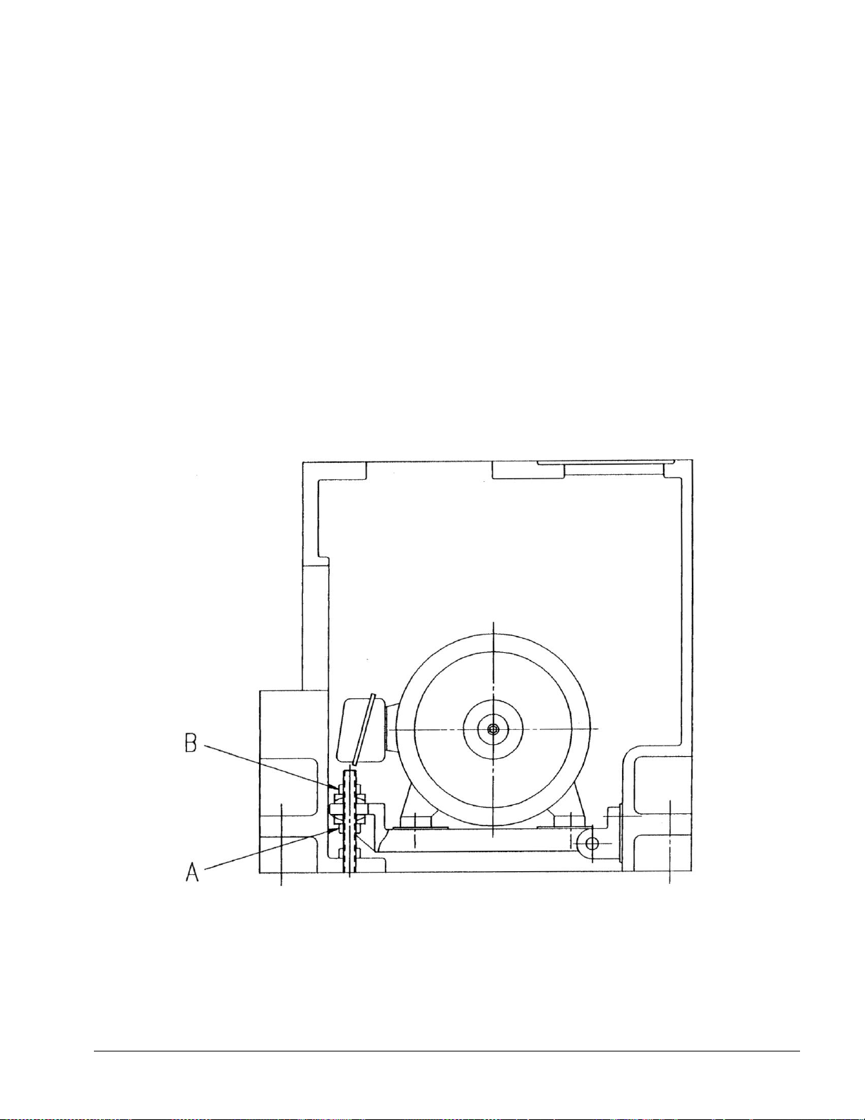
69
TRAK Machine Tools
Southwestern Industries, Inc.
TRAK TRL Lathe, ProtoTRAK RLX CNC Safety, Installation, Maintenance, Service & Parts List
on the pedestal. When removing the belt, loosen nut “G” and advance nut “H” until the belt has
i00491
sufficient slack to be removed from the pulleys.
When installing the belt, retract nut “H” and tighten nut “G”. Initially, tension the belt such that
there is no slippage when the lathe is started at its maximum speed.
Belt tension should be checked frequently during the first days of operation, and periodically
thereafter. Keep the pulleys and belt clean and free of any foreign material to ensure long life and
maximum traction.
Adjust the belt tensions using the “Pencil Tester” approach. For the 1630RX/1630HSRX, the
specification is 3.5 to 4.0 lbs using a ½ deflection. For the 1845RX and 2470, use 3.0-3.5 lbs.
5.1.8 Spindle Encoder Replacement
1. Unplug or remove all power from the lathe.
2. Remove the spindle cover to gain access to the encoder.
3. Loosen setscrews on flexible coupling and the bolts that hold the encoder on.
4. Slide the encoder off.
5. The spindle encoder assembly is only available as a complete unit. Do not disassemble.
Figure 5.1.8 – 1630RX, 1630HSRX, 1845RX, & 2470RX - Spindle Motor Belt Adjustment
5.1.9 Spindle Motor Removal
1. Unplug or remove all power from the lathe.
2. Loosen the belt tension. See section 5.1.8.
Page 76
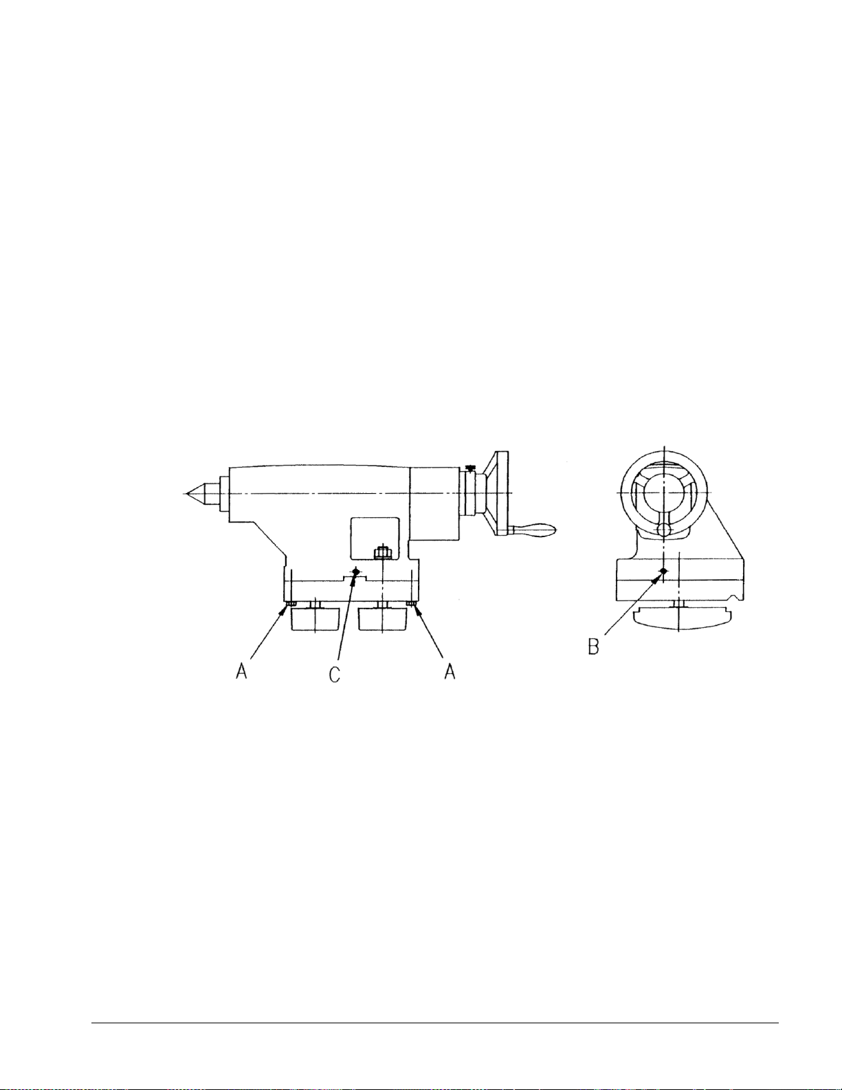
70
TRAK Machine Tools
Southwestern Industries, Inc.
TRAK TRL Lathe, ProtoTRAK RLX CNC Safety, Installation, Maintenance, Service & Parts List
3. Mark and remove motor electrical leads.
4. The motor is secured with four screws to a flange plate. See Figure 5.1.8
5. Because of the weight and size of the spindle motor, and the restricted working space, extreme
caution should be used in sliding the motor from its mounting plate.
5.1.10 Aligning Tailstock to Spindle
If there is taper appearing on the workpiece while machining when using the tailstock, the tailstock
will need to be realigned to the spindle. Follow the steps below.
1. Insert a gage bar between the spindle and tailstock, attach a base of a dial indicator to the
saddle, apply the needle of the indicator to the surface of the bar, then move the saddle
through the longitudinal travel. Document the measurement of its maximum difference from
end to end for later adjustment.
2. Release the 4 bolts labeled “A” in the drawing.
3. Release the screw labeled “B”.
4. Adjust screw “C” until the tailstock is aligned with the spindle.
5. Tighten up the locking nuts “A”.
Figure 5.1.10 - All RX Lathes - Tailstock Adjustment
5.1.11 Spindle Motor Wiring
The TRAK Lathe spindle motors are wired for 208 volts (low voltage configuration). The wiring
consists of 3-phase power for the motor and 208 volt power for the spindle motor fan. Please see
the motor junction box diagram for wiring information.
Each junction box contains 6 terminals. Make sure to hook up the wires to the same terminals after
the replacement motor is installed. Failure to do so may cause the motor to run in the wrong
direction.
The spindle motor fan wires are also found in the junction box. There is 1 hot wire, 1 neutral wire
and 1 ground wire. It does not matter which wires are connected to the hot and neutral wires. All
grounds from each cable are connected to either of the screws in the junction box.
00515
Page 77
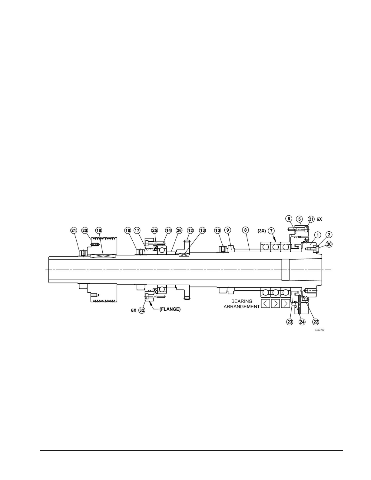
71
TRAK Machine Tools
Southwestern Industries, Inc.
TRAK TRL Lathe, ProtoTRAK RLX CNC Safety, Installation, Maintenance, Service & Parts List
5.1.12 Spindle Removal – 1630HSRX only (See Figure 5.1.2)
The following procedure is to remove the spindle for the 1630HS lathe.
1. Remove both spindle pulley belts.
2. Loosen three set screws on locknut item #21. Remove locknut.
3. Remove belt pulley item #20. Mark orientation of pulley to spindle shaft
4. Remove two keys item #19.
5. Loosen three set screws on locknut item 18. Remove locknut.
6. Remove six M6 socket head cap screws item #4
7. Cover end of spindle with aluminum or brass drift to prevent damage. Strike to remove spindle.
Carefully remove seal ring item #17 and encoder drive gear item #12 as spindle is driven
forward. Remove O-ring item #6.
8. Remove two bearings item #14
Note: the initial design of the spindle was different from what is reflected in Figure 5.1.12a and in
the parts list below. The spindle bearings are a 7013 bearing, p/n 24747.
Figure 5.1.12a - 1630HSRX – Spindle Assy P/N 24785 & Parts List Shown
Page 78

72
TRAK Machine Tools
Southwestern Industries, Inc.
TRAK TRL Lathe, ProtoTRAK RLX CNC Safety, Installation, Maintenance, Service & Parts List
Item
P/N
Title
Qty
1
24751
SPINDLE - 1630HS
1 2 24750
KEY 1 5
24752
COVER, FRONT
1 6 24753
O-RING
1 7 24754
BEARING-ANGULAR CONTACT U/ SET (3)-7014 P4
1 8 24755
SPACER SET
1 9 24756
COLLAR
1
10
24757
NUT-LOCK
1
12
24758
GEAR
1
13
24759
KEY 1 14
24760
BEARING-DEEP GROOVE-6012ZZ
1
17
24762
COLLAR
1
18
24763
NUT-LOCK
1
19
24764
KEY 1 20
24765
PULLEY, SPINDLE
1
21
24766
NUT-LOCK
1
22
24767
COLLAR
1
23
24770
CLAMP RING
1
24
24771
O-RING
1
25
25014
WASHER-WAVE SPRING
1
26
25015
SPACER-REAR BEARING-SPINDLE
1
30
M5-0.8X16 25B
SCREW-SHCS-STL-BO
1
31
M6-1.0X30 25B
SCREW-SHCS-STL-BO
6
32
M6-1.0X20 25B
SCREW-SHCS-STL-BO
6
i24785
Figure 5.1.12b - 1630HSRX – Spindle Assy P/N 24785 & Parts List Shown
5.2 Maintenance
5.2.1 Gib Adjustments
The objective of adjusting the gibs is to eliminate as much play in the cross slide and carriage sliding
surfaces as possible without having the tightness of the gib interfere with their free movement and
cause a decrease in the accuracy and/or performance of the machine due to excessive friction.
5.2.1.1 Cross Slide Gib Adjustment
1. Remove the yoke bolts from the top of the cross slide and slide it back and forth and feel for
any looseness in the system. If it is loose tighten up the adjusting screws.
NOTE: Adjustments should be made where the gibs are worn the worst.
2. Turn the X-axis ball screw with a torque wrench and measure the torque. The torque should be
less than 15 in/lb. and consistent over the travel of the X-axis. If the measurement is higher
than this then loosen the gib. Make sure the cross slide is aligned properly. One easy way to
check for this is to remove the yoke bolts and see if the yoke springs back into position.
Misalignment is also evident if the torque is higher when the yoke is up against the rear bearing
housing.
Page 79
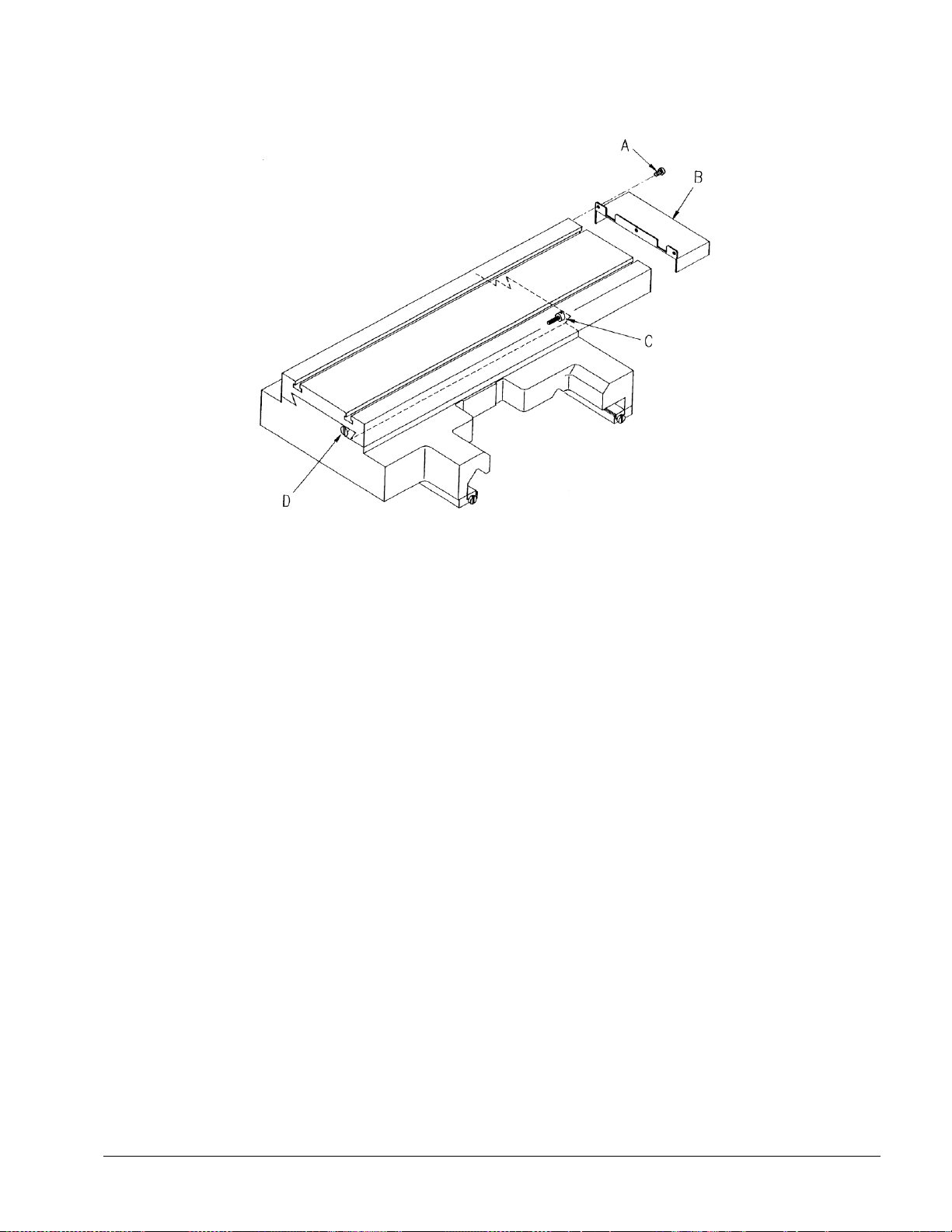
73
TRAK Machine Tools
Southwestern Industries, Inc.
TRAK TRL Lathe, ProtoTRAK RLX CNC Safety, Installation, Maintenance, Service & Parts List
Figure 5.2.1.1 - All RX Lathes - X Axis Gib
5.2.1.2 Z-Axis Gib Adjustment
1. Mount a dial indicator on the Z-axis ways and locate on top of the carriage.
2. Lift the carriage up to measure the amount of play. The dial indicator should not move more
than 0.001”. If it moves more, tighten the gibs. Make sure not to over tighten the gibs.
Page 80
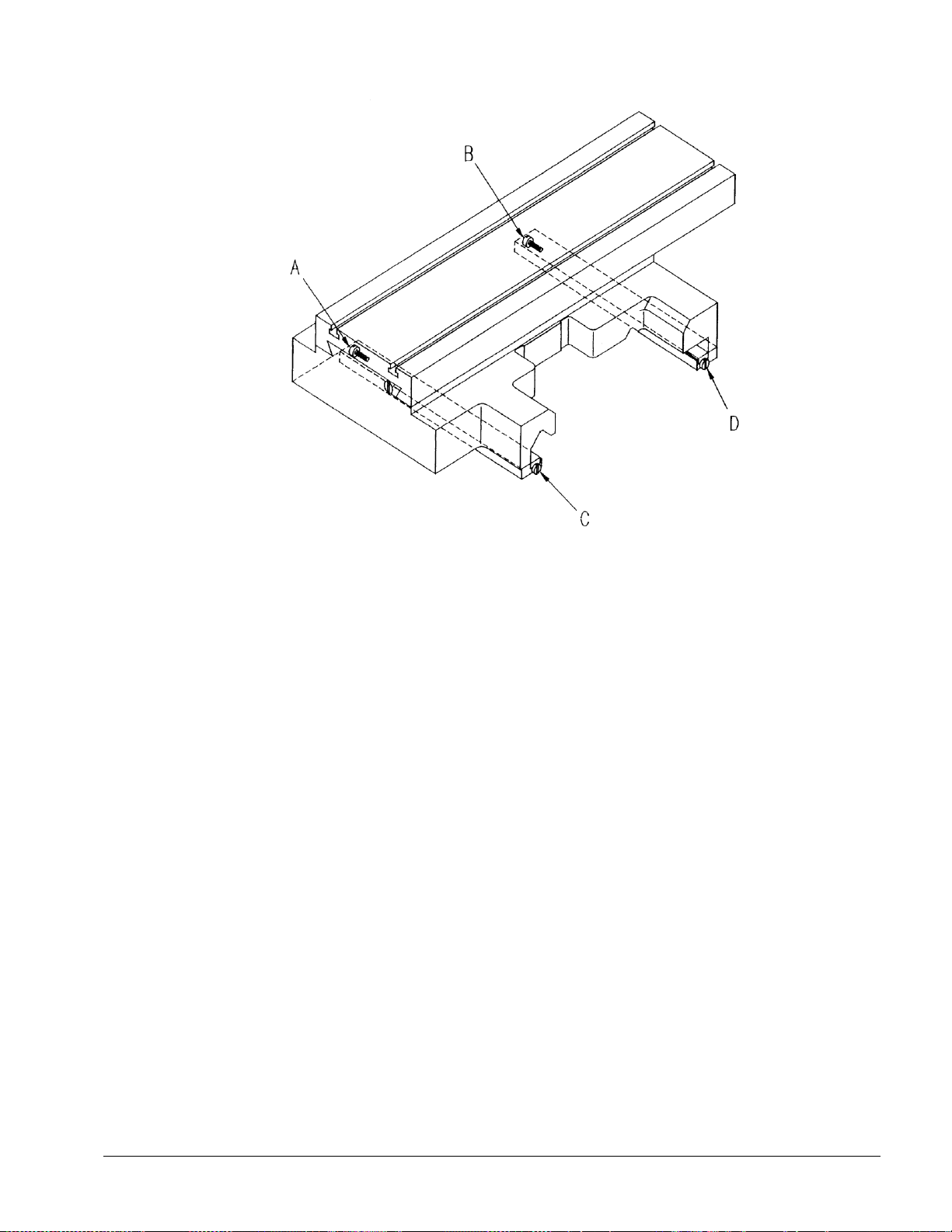
74
TRAK Machine Tools
Southwestern Industries, Inc.
TRAK TRL Lathe, ProtoTRAK RLX CNC Safety, Installation, Maintenance, Service & Parts List
Figure 5.2.1.2 - All RX Lathes - Z Axis Gib
5.2.2 Calibration & Backlash Constants
Calibration and backlash constants were set as part of the installation and set-up of your system.
They should be re-set when indicated in the Troubleshooting section or after the replacement of the
computer module, or any parts of the drive train.
Calibration is used to teach the machine a known distance. We typically calibrate our machines over
a 150 mm distance. There is no limit to how far you can calibrate the machine.
5.2.2.1 Calibration
NOTE: Calibration usually is only done after replacing a computer module or adjusting the drive train.
1. Recheck machine level and adjust as necessary.
2. Press the “SERV CODE” soft key.
3. Input 123 on the keyboard, then press the “INC SET” key.
4. Input the “X” key to tell the control the x-axis is being calibrated.
5. Place the .0001 indicator in the spindle and set up the metric standard on the cross slide.
Make sure the standard is parallel to the cross slide by using a combination square. Ensure
that the standard is set up so that the readings will be taken with the cross slide extended
towards the operator and moving in towards the motor end of the X-axis.
6. When the indicator is zeroed at the beginning of the standard press the “INC SET” key.
7. Move the cross slide towards the motor side of the x-axis until the indicator zeros on the end
of the standard. Input 300 on the keyboard.
8. If the calibration was successful the screen will return to the set up screen.
Page 81
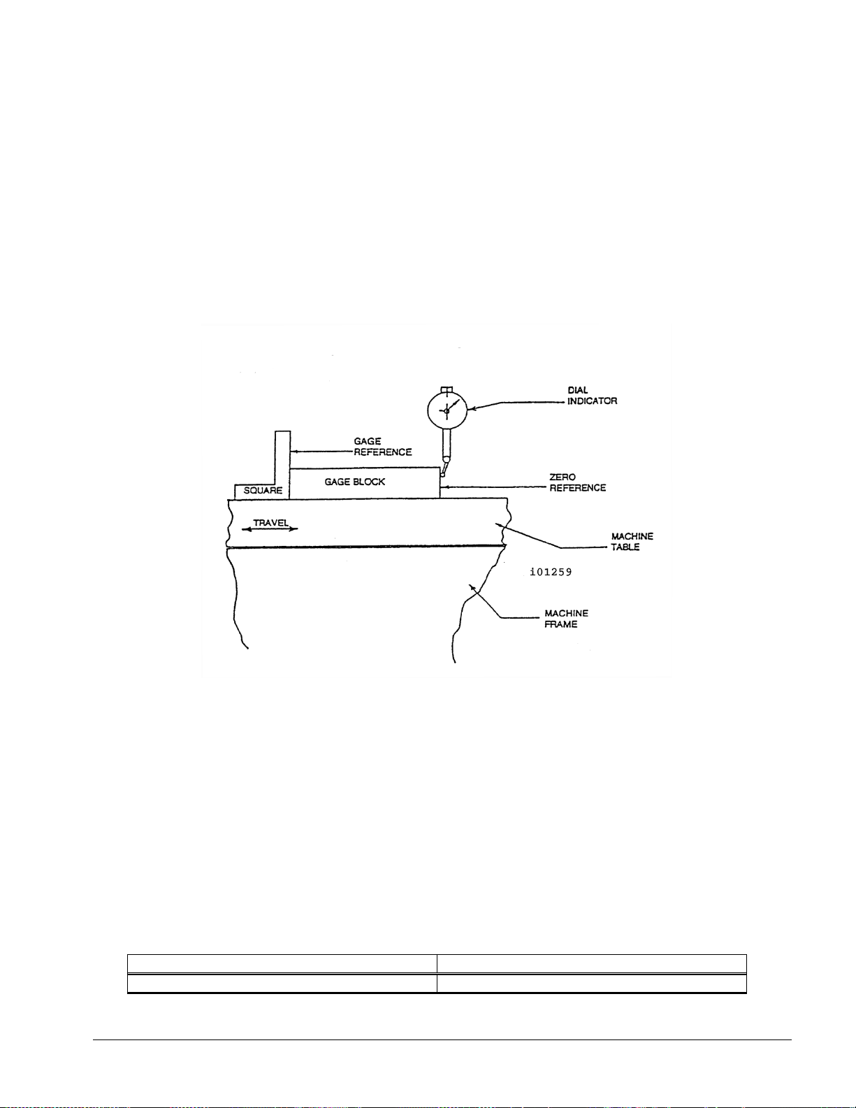
75
TRAK Machine Tools
Southwestern Industries, Inc.
TRAK TRL Lathe, ProtoTRAK RLX CNC Safety, Installation, Maintenance, Service & Parts List
9. Press the “SERV CODE” soft key.
Conversation Says
You Do
a. ---
a. Press MODE
10. Input 123 on the keyboard, then press the “INC SET” key.
11. Press the “Z” key to tell the control that the z-axis is being calibrated.
12. Set up the metric standard on the Z-axis ways.
13. Set up the magnetic base and .0001 indicator on the cross slide.
14. When the indicator is zeroed at the beginning of the standard press the “INC SET” key.
15. Move the saddle towards the chuck until the indicator zeros on the end of the standard, then
press the “INC SET” key.
16. Input 150 on the keyboard.
17. If the calibration is successful the screen will change to the set up screen.
Figure 5.2.2.1 - All RX Lathes - Calibration Set-Up
5.2.2.2 Backlash Compensation
Code 127: Calculate X or Z Backlash Constant
Every mechanical system has at least a little backlash or lost motion. It is produced by the small
amount of play between the gibs and ways, and mostly by the accumulative bending or elasticity of
all the parts of the drive train under load. The backlash constant is factory set, but may need to be
adjusted periodically.
1. Set a .0001-inch dial indicator in the spindle, and touch off on a block or the vise along the
direction (X or Z) you wish to check, or set the backlash constant.
2. Turn on the ProtoTRAK and at the Main Menu, follow the procedure below precisely:
Page 82

76
TRAK Machine Tools
Southwestern Industries, Inc.
TRAK TRL Lathe, ProtoTRAK RLX CNC Safety, Installation, Maintenance, Service & Parts List
b. Select Mode
b. Press SET UP
c. Select
c. Press SERV CODES
d. Select
d. Press “B”
e. Select Code 127
e. Press X or Z
f. Backlash Value = _ _ _ _
f. What is shown is the current value.
Follow the instruction on the screen and
press the appropriate soft keys.
Wait a few seconds between each
press of INCR VALUE or DECR VALUE.
g. The following is an example of what you
might see when running this code.
For example, if the up and down "Oscillation
Value" shown in the conversation line is .00278
inch, and the dial indicator is moving back and
forth .0012, then the true backlash value is
.00278 -.0012 = .00158 inch. Input this by
pressing MODE, SET UP, SERV CODE, 128, SET
and then .00158, SET, RETURN.
3. The X backlash identified and stored in Step 2 should be less than 0.003” on a new machine. If
it is appreciably larger, inspect the drive train for loose bolts, brackets, bearings, etc.
The backlash can also be found manually with a 0.0001” indicator using the following method.
Load the indicator to zero from one direction and zero out the DRO.
Move the indicator to 0.002” and then back to zero. Do not over shoot 0, otherwise
start over.
Whatever number appears on the screen is the backlash value.
Enter this value into service code 128.
After entering this number redo the process. The DRO and indicator should now both
read 0.
CODE 128: Input Backlash Constant
Code 128 allows you to enter the backlash values for each axis. It displays the value after it
enters.
Be sure not to enter too much backlash on any given axis. Too much backlash in the system
may cause bi-directional repeatability problems or axis motor searching.
5.2.3 Lubrication
5.2.3.1 Headstock Lubrication
1630, 1845, 2470: The pump needs to be primed if left unused for a couple days.
Priming the pump entails turning the spindle on at 1000 RPM for a few seconds.
An oil pump provides lubrication for an even distribution of oil to all the gears and bearings in the
headstock. One of the oil lines pumps oil to a site glass located on the headstock. Periodically
check to see that oil is flowing. Oil flows to this site glass only when the spindle is running for the
1630, 1845 and 2470. The 1630HS does not require headstock oil.
The plug to drain the headstock is located under the spindle cover towards the bottom of the casting. See
the figure below. Oil can be added to the reservoir by a plug in the top of the headstock cover or by
removing the cover and pouring it into the headstock. There is a level site glass located under the spindle
cover. The headstock reservoir holds different amounts depending on the machine. See Section 2.2. Fill
the headstock with Mobil DTE 24 oil or an equivalent grade.
The headstock gearbox oil must be drained and flushed after the first 150 hours of operation. A small
percentage of kerosene may be added to the gearbox to flush out dirt and sediment. Operate the machine
Page 83
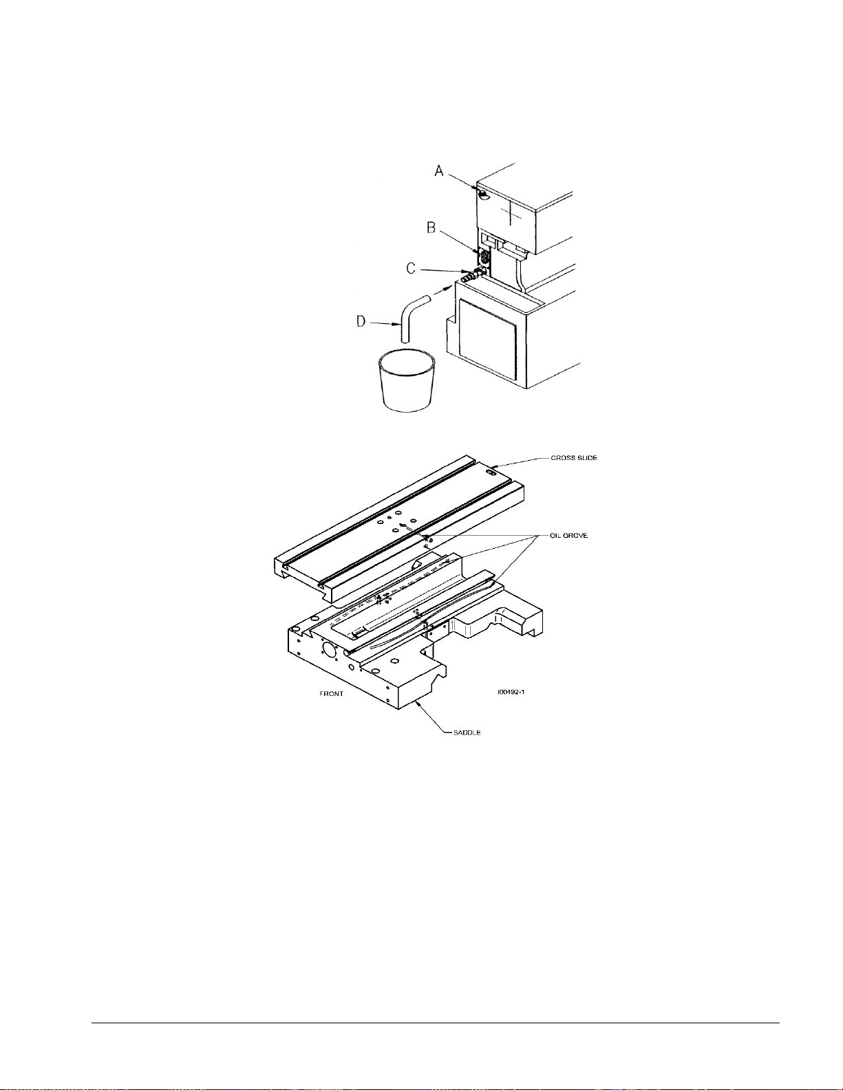
77
TRAK Machine Tools
Southwestern Industries, Inc.
TRAK TRL Lathe, ProtoTRAK RLX CNC Safety, Installation, Maintenance, Service & Parts List
for several minutes without load so that the flushing oil can circulate through the reservoir and remove the
dirt. The flushing oil must then be drained and new oil added. Do not flush with solvents, as that will
soften the paint. Thereafter, the oil should be flushed and drained every 1500-2000 hours of operation.
Figure 5.2.3.1a - Headstock Oil Removal
i00514
Page 84
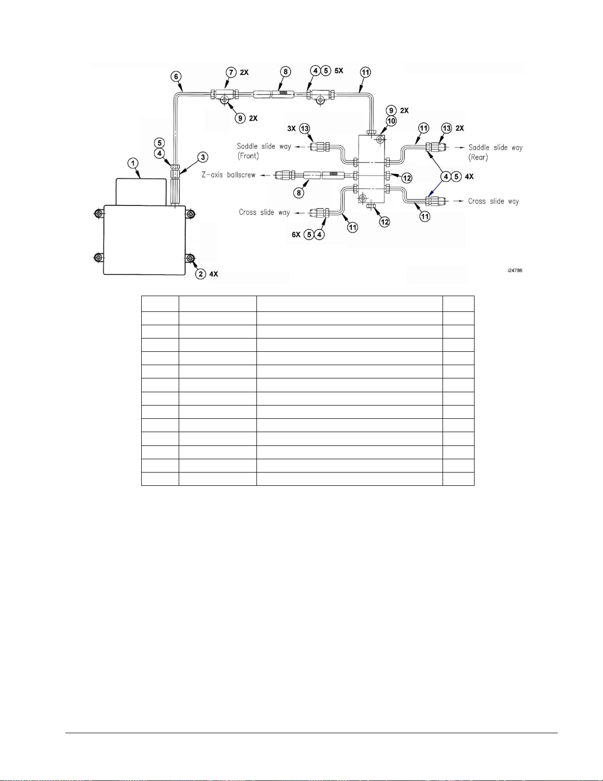
78
TRAK Machine Tools
Southwestern Industries, Inc.
TRAK TRL Lathe, ProtoTRAK RLX CNC Safety, Installation, Maintenance, Service & Parts List
Item
P/N
Title
Qty
1
22291
LUBRICATION PUMP-WITH CABLE
1
2
M6-1.0X12 25B
SCREW-SHCS-STL-BO
4
3
PC4
VALVE-CKECK 1/8"
1 4 PA4
NUT-COMPRESSION 4mm
16
5
PB4
SLEEVE-COMPRESSION 4mm
16
6
16386
TUBING NYLON 4MM DIA #5N25C
A/R 7 PN-6
UNION-FEMALE
2
8
106711
HOSE- FLEXIBLE 4MM
A/R
9
M5-0.8X20 25B
SCREW-SHCS-STL-BO
4
10
D12
OIL DISTRIBUTION JUNCTION
1
11
A4
TUBING-4MM ALUM
A/R
12
PG004
PLUG- M8 X 1.0
2
13
PD-401
ADAPTER-STRAIGHT
5
i24786
Figure 5.2.3.1b - 1630RX & 1630HSRX – System Lubrication – P/N 24786 & Parts List
For the 1845 and 2470 lathes, see section 8 for a way lubrication diagram.
5.2.3.2 Tailstock
Three oilers located on top of the spindle housing lubricate the spindle and screw. The bedways on
which the tailstock slides should be cleaned and oiled frequently.
Page 85
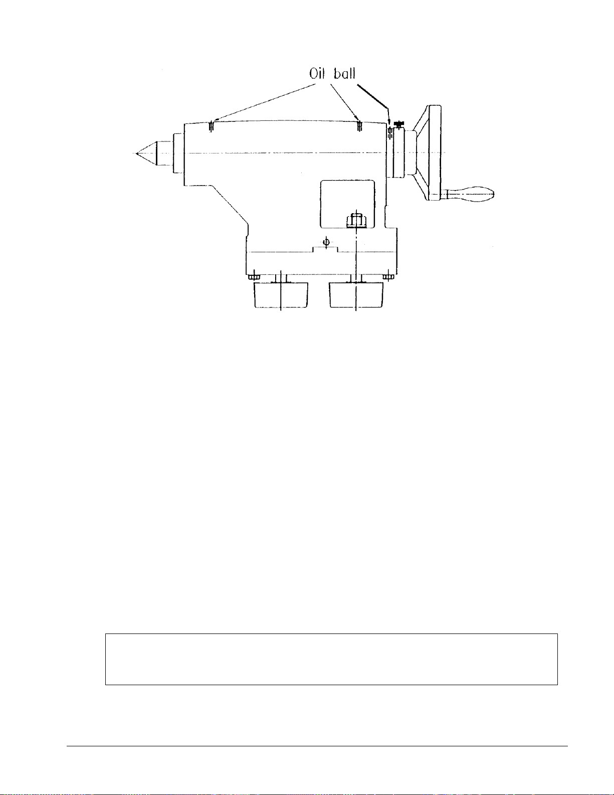
79
TRAK Machine Tools
Southwestern Industries, Inc.
TRAK TRL Lathe, ProtoTRAK RLX CNC Safety, Installation, Maintenance, Service & Parts List
Figure 5.2.3.2 - All RX Lathes - Tailstock Lubrication
5.2.3.3 Miscellaneous Information
For all oilers on the machine, use medium S.A.E. NO. 30 machine oil. Before filling reservoirs or oil
cups, always wipe off with a clean rag any accumulation of old oil, grease or dirt that might get into
a part being lubricated.
Do not mix detergent type automotive oil, or multi-purpose oils with the regular grade of S.A.E. No.
30 lubricating oil.
5.2.4 X & Z Limit Switch Adjustments
5.2.4.1 X-Axis Limit Switch-Stop Installation & Adjustment
The limit switch-stops for the X-axis are mounted to the side of the crosslide. They are slotted for
adjustment front to back. Each limit switch-stop must be set to a specific distance from the end of
the crosslide in order to maximize travel and simultaneously prevent serious damage to the machine
in the event of a crash. All limit switches are set at the factory for maximum travel. The switch is
mounted to the carriage. The switch and the stops are covered by a sheet metal cover.
Procedure for setting X limit switch:
1. Loosen the stops on each side of the crosslide.
2. Slowly move the crosslide to the extremes of travel.
3. In DRO mode set X = 0 ABS.
CAUTION!
The limit switch must be triggered a minimum of ½” before the machine reaches its
travel limits in both directions. This allows sufficient room for the servomotors to stop
when the limit switch is hit at 250 ipm.
4. Using the DRO display, back the table off 1/2".
5. Tighten the stops in place.
Page 86

80
TRAK Machine Tools
Southwestern Industries, Inc.
TRAK TRL Lathe, ProtoTRAK RLX CNC Safety, Installation, Maintenance, Service & Parts List
6. Jog the table at 250ipm to each side and verify that the limit switches are working properly.
Also, make sure that the table does not exceed its travel and crash.
5.2.4.2 Z-Axis Limit Switch-Stop Installation & Adjustment
The limit switch-stops for the Z-axis are mounted on the side of the bed at the headstock side and
attached by a bracket to the tailstock for the positive direction. Each limit switch-stop must be set
to a specific distance from the headstock and tailstock to maximize travel and simultaneously
prevent serious damage to the machine in the event of a crash. The limit switch bracket and stops
contains slotted holes, which allow for side-to-side positioning adjustments of the limit switch
assembly.
Procedure for setting Z limit switch:
1. Slowly move the carriage to the front of the spindle with the handwheel until you are
approximately ¾” from the spindle.
CAUTION!
The limit switch must be triggered a minimum of ½” before the machine reaches its
travel limits in both directions. This allows sufficient room for the servomotors to stop
when the limit switch is hit at 250 ipm.
2. Lock the stop in place and make sure when you hit the stop the switch is triggered and the
carriage comes to rest before hitting the spindle. Make sure you have adjusted the stop far
enough away to prevent a crash.
WARNING!
The Z-axis limit switch at the headstock end is set to prevent crashes into the spindle.
It is not adjusted for the various chuck or collet closer combinations.
3. Perform a similar adjustment at the tailstock end of the bed. Make sure the carriage does not
hit the tailstock when the limit switch is triggered at maximum feedrate. At the tailstock end
there is slight adjustment up and down and more adjustment side to side.
Page 87

81
TRAK Machine Tools
Southwestern Industries, Inc.
TRAK TRL Lathe, ProtoTRAK RLX CNC Safety, Installation, Maintenance, Service & Parts List
6.0 SWI Turret Options
6.1 4 & 8 Tool Turret Option
Due to the turret weight, special handling is required. Personal injury or damage to the turret
and/or lathe may occur if not handled properly.
6.1.1 Field Installation Instructions
1. Refer to the Turret Option Drawings in Section 7 for the 4 or 8 tool Turret to be installed on the
1630, 1856 or 2470 lathes.
2. The turret and cabling is installed as per the Turret Option Drawing for the specific lathe.
3. Note that the center line of the turret must be shimmed.
4. Note the connections from the turret and air regulator to the Computer Module as shown in the
referenced drawing.
5. Verify air has been hooked up to the machine. The air regulator is mounted to the bottom left
of the electrical cabinet. Refer to the Turret Option Drawings in Section 7.
6. Ensure the turret work area is clear and ready to be used.
7. To verify the turret is working properly, run a program with all 4/8 tools. To run the program,
enter a home position in Setup Mode. Make sure you set the X and Z absolute zero position 12
to 18 inches from the chuck. Set the home position to X = 3 and Z = 3. Run a program and
make sure the turret moves to the correct tool stations programmed. Verify that the turret
positions to each tool station.
WARNING!
8. Turn power on to the machine.
9. On the Pendant, press the “POWER RESET” key. Wait for the wait LED to turn ON.
10. You may load a program using the “PROG IN/OUT” key followed by selecting the desired
program. Press “OK”.
11. Press the “DRO” key. For the tools set up, select the tool number to use.
12. Press the “SET-UP” key followed by the “HOME TURRET” key. Enter the desired Tool # followed
by pressing the “ABS SET” key.
13. The message “Turret is now homed and ready to use.” should appear. You are ready to run
your program.
6.1.2 Removing the 4 Tool Turret from the Lathe
1. Turn the main power off to the machine.
2. Unhook the air line from the air regulator.
3. Disconnect the air lines and electrical lines to the Computer Module. The 2 air lines need to be
disconnected at the Air Regulator. Refer to the Turret Option Drawings in Section 8 for the 4 or 8 tool
Turret to be installed on the 1630, 1845 or 2470 lathes.
Page 88
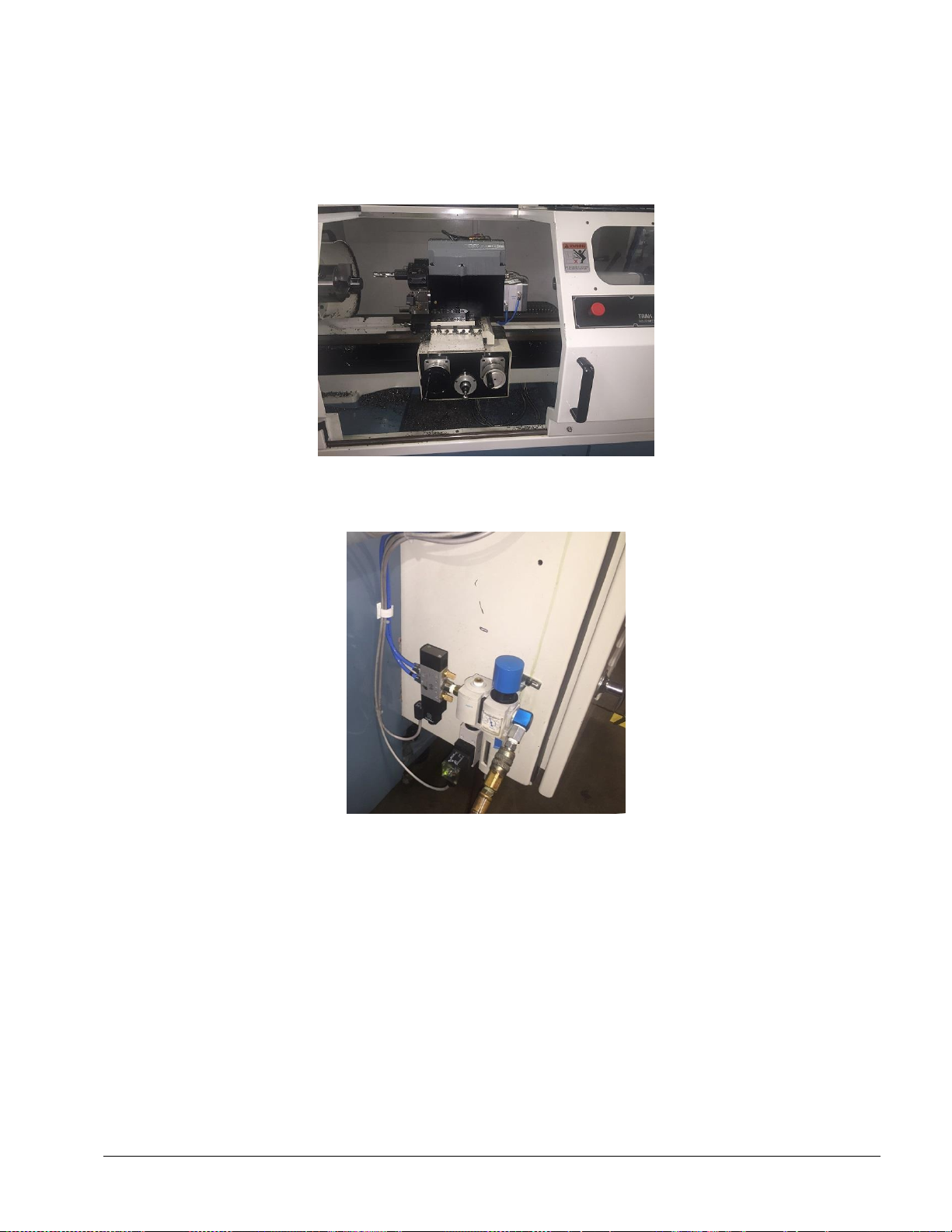
82
TRAK Machine Tools
Southwestern Industries, Inc.
TRAK TRL Lathe, ProtoTRAK RLX CNC Safety, Installation, Maintenance, Service & Parts List
6.1.3 Removing the 8 Tool Turret from a Lathe
1. To remove the TRAK CNC Turret from a Lathe, position the Z Axis in about the middle of its
travel, position the X Axis cross slide to max travel closest to the operator. E-Stop machine for
safety. This will also remove power from the turret and turret control box.
2. Disconnect the main air, then, disconnect the air lines from the solenoid valves. Cut any tie-
wraps attaching the airlines to the solenoid wiring and remove from the cable clamps.
Page 89
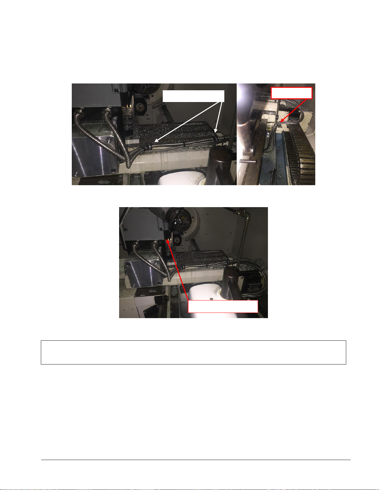
83
TRAK Machine Tools
Southwestern Industries, Inc.
TRAK TRL Lathe, ProtoTRAK RLX CNC Safety, Installation, Maintenance, Service & Parts List
3. Disconnect the 2 cables from the turret to the Computer Module. Remove cables from cable
Remove Cable Clamps
Cut Ty-Wraps
Remove coolant line.
clamps mounted to the sheet metal cabinet. Cut any tie-wraps attaching cables to cabinet.
Remove cables and cable clamps from the cross slide, cut any ty-wraps attaching cables to the
cross slide. Once cables and airlines are detached from machine, coil up in preparation of
removing the turret.
4. Close coolant valve and remove coolant line from the turret.
5. Insert the eye bolt that came with the turret into the top cover.
CAUTION!
Heavy! The 1” turret weighs 110 lbs without the mounting base. Use proper lifting equipment
to avoid injury and or damage to the turret.
Page 90
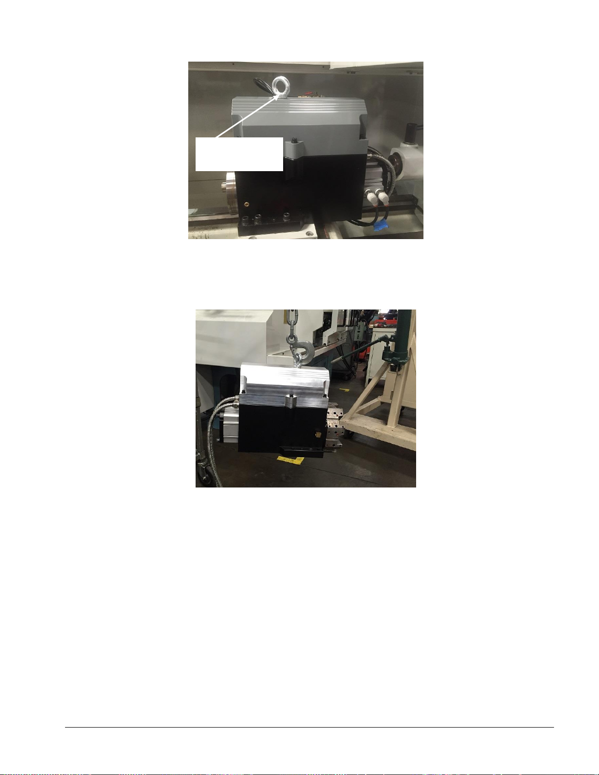
84
TRAK Machine Tools
Southwestern Industries, Inc.
TRAK TRL Lathe, ProtoTRAK RLX CNC Safety, Installation, Maintenance, Service & Parts List
Eye bolt used for
lifting turret.
6. Using an engine hoist or chain hoist, attach it to the eye bolt. Remove the 6 screws that mount
the turret to the mounting base. Slowly raise the hoist until the turret is clear of the mounting
base. Slowly move the hoist away from the machine. Lower the turret onto a cart, pallet or the
shipping crate the unit was shipped in.
7. To reinstall reverse the above steps. Insure all mounting surfaces are clean and free of chips or
debris before mounting the turret. Turret is not pinned so it will need to be aligned for maximum
accuracy.
6.1.4 Troubleshooting the Turret
The following fault messages will appear on the screen when there is a problem with the turret.
Fault 85 – Impossible Tool Position
This message will appear if the turret goes to a tool number that you did not select. For
example, the operator chose Tool 2 and the turret went to Tool Station 6. To fix this problem,
re-initialize the system by choosing Service Code 147. Contact Southwestern Industries
Customer Service.
Page 91

85
TRAK Machine Tools
Southwestern Industries, Inc.
TRAK TRL Lathe, ProtoTRAK RLX CNC Safety, Installation, Maintenance, Service & Parts List
Fault 86 – Turret Power Problem
This message will appear if the power is interrupted to the turret. It could indicate that no
power or low power is getting to the turret. Check that the Computer Module and AC
Drive/Motor (for the 8 Tool Turret) is receiving power.
Fault 87 – Turret Air Pressure Problem
This message will appear if the air pressure sensor senses low air or no air pressure. The
recommended air pressure for the turret is 90 psi. The air pressure should be 90 psi and no
more than 100 psi for the turret to work correctly. Do not exceed 100 psi. This will void
the warranty on the turret.
Fault 88 – Turret Not Initialized
This message will appear if the turret does not know its present position. An example of this
would be if the turret stops in the middle of a tool change. An interruption of power or air may
cause this fault. Pressing the E-stop button can also cause this problem if the tool is not in a
known position. In order to initialize the turret, go to SETUP, TOOL GROUP, 4 or 8 TOOL,
followed by HOME turret.
Note: The air flow control fitting for the Turret clamp also plays a part in how long it
takes for the turret to finish the initialization routine. Thus the air flow control clamp
should be set to 2.5 turns from full open.
Fault 89 – Turret Time Out
This message appears if the turret does not get to position after a few seconds. This may be
caused by an internal problem inside the turret such as a broken gear or jammed component.
Very low air pressure may also cause this fault. It should take no longer than 2 or 3 seconds for
the turret to move between positions.
6.1.5 Turret Maintenance
It is recommended that the turret be lubricated twice a year after the first year. The worm and
worm gear should be lubricated with quality lithium based grease every 6 months after the first
year. Remove the side cover, top cover and stepper motor and grease the gears. When remounting, ensure that the O-ring and side seal are intact so that no coolant can enter the turret.
6.1.6 Warranty Issues
The SWI turret is warranty for 1 year. If it is determined that there is a problem with the turret it
will need to be returned for repair. Control problems are warranted by Southwestern Industries,
Inc. for 1 year.
Page 92

86
TRAK Machine Tools
Southwestern Industries, Inc.
TRAK TRL Lathe, ProtoTRAK RLX CNC Safety, Installation, Maintenance, Service & Parts List
7.0 Introduction to Self-Service
The objective of this section of the manual is to allow the user of the ProtoTRAK Control to resolve the
majority of potential service problems.
This manual assumes that the user is not experienced with CNC troubleshooting and repairs. Special tools
are not required for the procedures described in the manual.
Please see Sections 3 for basic troubleshooting sections of the manual.
7.1 When You Have a Service Problem
SWI recommends that you consult this manual or our web site first. We also have a Dozuki site with
detailed troubleshooting procedures https://trakmtsupport.dozuki.com/ Often it will be possible for you to
resolve the problem yourself or isolate the problem to a particular cause.
Your next step is to contact the SWI Customer Service Group for assistance.
7.1.1 Communication with the SWI Customer Service Group
SWI Service Department Direct Line: (800) 367-3165
Web Address – www.trakmt.com
This phone line rings directly into the SWI Customer Service Group. If a Customer Service
Representative (CSR) is not available within the first few of minutes, your call is transferred into our
voice mail system.
Our voice mail is continuously monitored. If you have an emergency, indicate this in your message.
Our Service Voice Mail box number is 555.
SWI Service Department Direct Fax number (310) 886-8029
Customer Service Group hours:
Monday - Friday 7:00 AM to 4:30 PM Pacific Time.
SWI observes a normal holiday schedule.
7.2 Replacements
7.2.1 Exchange Program
SWI keeps in stock the major subassemblies required to resolve service problems. With very few
exceptions, the part needed to resolve any given service problem is on the shelf and ready to ship.
A little bit of troubleshooting on your part means that we can get the right part to you fast.
After replacing the failed unit with the replacement unit, simply put the failed unit in the same box
that the replacement part came in and ship it back to us via UPS ground service.
This unique Exchange program gives our customers access to refurbished “like-new” subassemblies
that have been brought up to current design revisions and go through the same QC procedures as
our new products. These high-quality replacement units are available at a fraction of the price of a
new subassembly.
7.2.2 Return Material Authorization (RMA) Number
All shipments of replacement parts are accomplished through our Return Material Authorization
(RMA) system. At the same time the CSR is diagnosing the problem and ordering the part, they will
issue an RMA number that will allow us to efficiently process the return part.
Page 93

87
TRAK Machine Tools
Southwestern Industries, Inc.
TRAK TRL Lathe, ProtoTRAK RLX CNC Safety, Installation, Maintenance, Service & Parts List
8.0 Drawings & Parts Lists
8.1 29531 - DRIVE ASSY - X AXIS - 1630RX
8.2 29533 - DRIVE ASSY - X AXIS - 1845RX
8.3 29535 - DRIVE ASSY - X AXIS - 2470RX
8.4 29532 - DRIVE ASSY - Z AXIS - 1630RX
8.5 29534 - DRIVE ASSY - Z AXIS - 1845RX
8.6 29536 - DRIVE ASSY - Z AXIS - 2470RX
Page 94
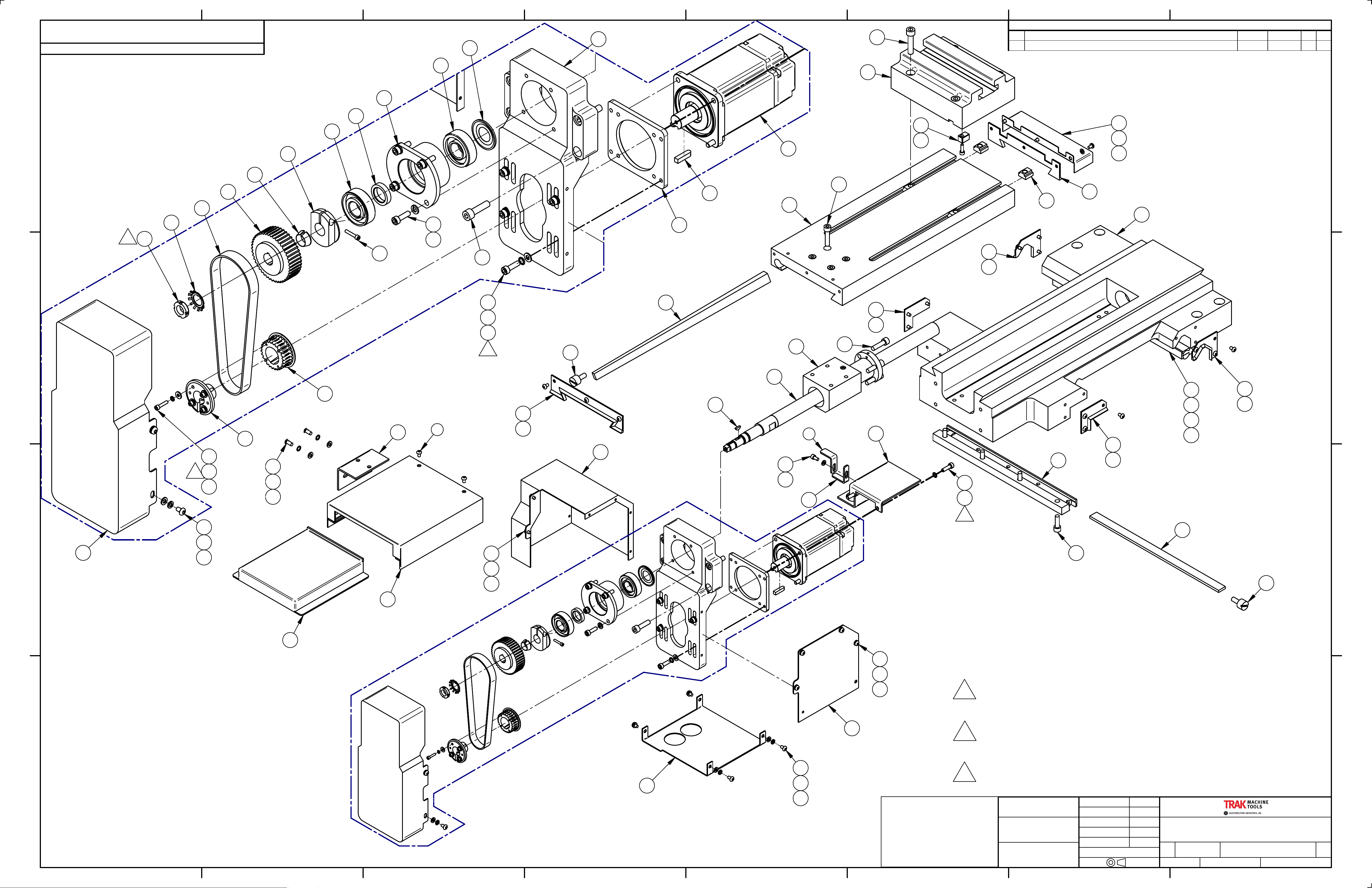
NOTICE: THIS DESIGN WAS ORIGINATED BY AND EMBODIES A CONFIDENTIAL PROPRIETARY DESIGN
OWNED BY SOUTHWESTERN INDUSTRIES. IT IS DISCLOSED IN CONFIDENCE FOR A SPECIFIC PURPOSE
AND THE RECIPIENT HEREOF AGREES NOT TO MAKE ANY REPRODUCTION, DISCLOSURE OR OTHER USE
OF THIS INFORMATION WITHOUT THE WRITTEN CONSENT OF SOUTHWESTERN INDUSTRIES.
© SOUTHWESTERN INDUSTRIES, INC. 2018 ALL RIGHT RESERVED
D
10
12345678
REVISIONS
1 REF
83(4X)
6REF
REV
PRODUCTION RELEASE
A
ECN DATE DFTDESCRIPTION
14959
02/06/19
8REF
63REF
7REF
7REF
64(2X)
34 REF
8REF
76(2X)
86 (3X)
21 REF
9REF
75 (3X)
AC
ENG
LG
D
C
3
14
13
15
12
79 (4X)
89 (4X)
99 REF
DETAIL A
81 (4X)
794X
954X
884X
2
82 (4X)
24 REF
33REF
65 (4X)
59 REF
32 REF
20 REF
56REF
75(3X)
45REF
57REF
75(3X)
C
5REF
62(2X)
81(4X)
100 4X
106 4X
1
105 4X
75 (4X)
26
2REF
25
11
61 (2X)
51 REF
55 REF
75 (3X)
60REF
44 REF
70
75 (2X)
75(3X)
27
23REF
80 (4X)
58 REF
35 REF
742X
952X
882X
77
86
28
79 4X
95 4X
50 REF
75 (3X)
2
44 REF
B
87 (4X)
36REF
86 (4X)
75(2X)
80 (4X)
B
87(2X)
86(2X)
61 (2X)
66REF
67REF
75 (4X)
87 (4X)
86 (4X)
NOTES: (UNLESS OTHERWISE SPECIFIED).
1 TORQUE 6-32X5/8 25B SCREWS (ITEM 100) TO 22 IN-LBS IN A CROSSING
A
A
PATTERN (B7).
38 REF
2 TORQUE M6-1.0X20 25B SCREWS (ITEM 84) THAT FASTENS TO MOTOR
ADAPTER (ITEM 79) TO 5 FT LBS OR 60 IN LBS (B3,C5).
A
75 (4X)
3 TORQUE N02 LOCKNUT (ITEM 14) TO 20 FT-LBS (C8)
37REF
87 (4X)
86 (4X)
DIMENSIONS ARE IN INCHES
DEC. .X = ±.1, .XX = ±.01, .XXX =
±.005,
ANGLES .XX = ±0°30'
FRACTIONS = ±1/8
FINISH = 125 RMS
REMOVE ALL SHARP EDGES
MASK ALL TAPPED HOLES
DIMENSIONING PER ASME Y14.5
MATERIAL
FINISH
DRAWN BY
ENGINEER
CHECKER
FE
THIRD ANGLE PROJECTION
AC
LG
DATEAPPROVALS
02/13/18
02/13/18
TITLE
DRIVE ASSY - X AXIS - 1630RX
SIZE
SCALE:
CODE IDENT. NO. DWG NO. REV
D
06238
29531
SHEET OF
1
A
2
12345678
Page 95
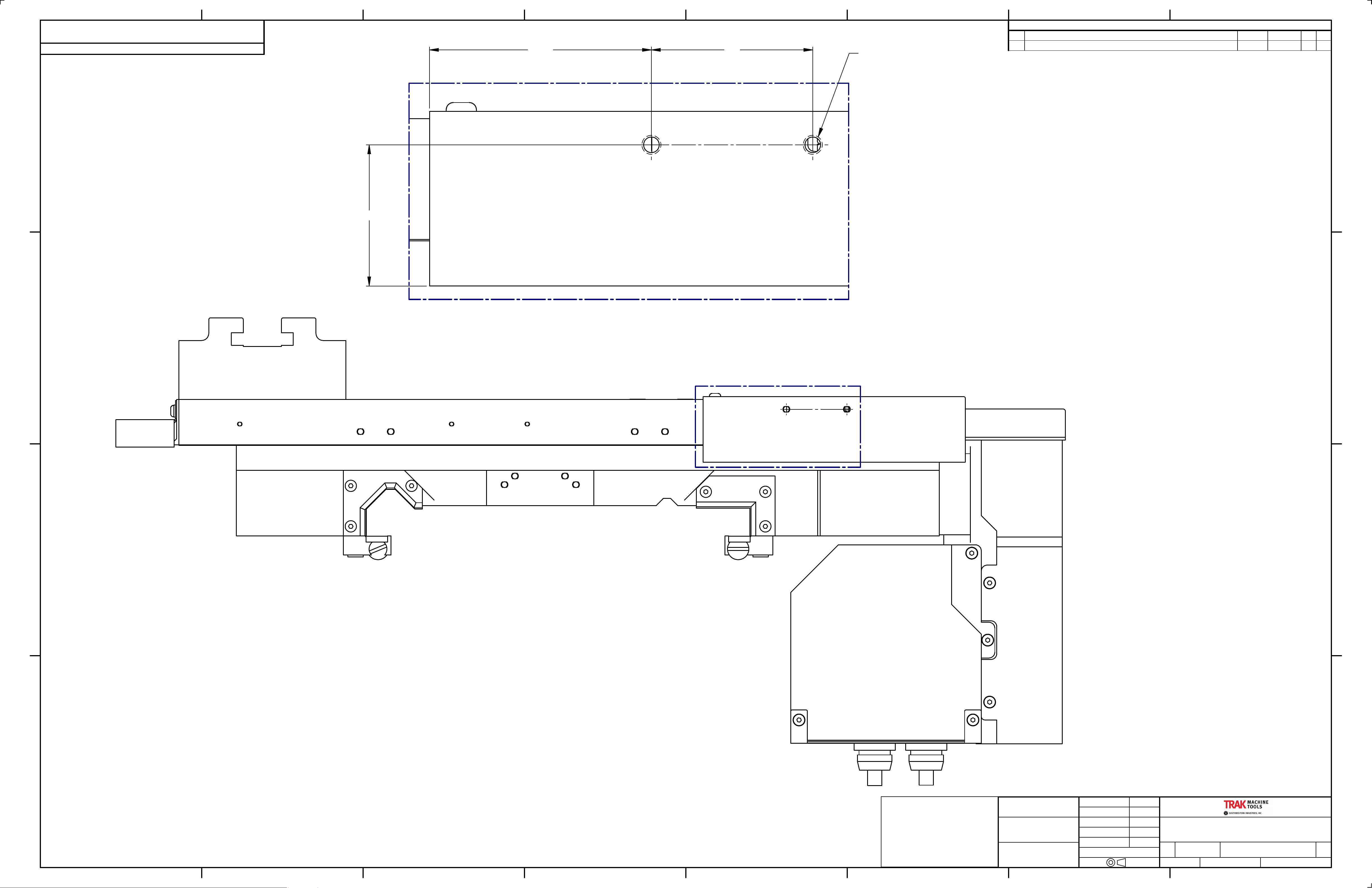
NOTICE: THIS DESIGN WAS ORIGINATED BY AND EMBODIES A CONFIDENTIAL PROPRIETARY DESIGN
OWNED BY SOUTHWESTERN INDUSTRIES. IT IS DISCLOSED IN CONFIDENCE FOR A SPECIFIC PURPOSE
AND THE RECIPIENT HEREOF AGREES NOT TO MAKE ANY REPRODUCTION, DISCLOSURE OR OTHER USE
OF THIS INFORMATION WITHOUT THE WRITTEN CONSENT OF SOUTHWESTERN INDUSTRIES.
© SOUTHWESTERN INDUSTRIES, INC. 2018 ALL RIGHT RESERVED
12345678
REVISIONS
REV
PRODUCTION RELEASE
2.02.750
M6-1.0 TAP
A
ECN DATE DFTDESCRIPTION
14959
02/06/19
2X THRU
AC
ENG
LG
D
D
1.750
C
DETAIL Z
C
B
Z
B
A
DIMENSIONS ARE IN INCHES
DEC. .X = ±.1, .XX = ±.01, .XXX =
±.005,
ANGLES .XX = ±0°30'
FRACTIONS = ±1/8
FINISH = 125 RMS
REMOVE ALL SHARP EDGES
MASK ALL TAPPED HOLES
DIMENSIONING PER ASME Y14.5
MATERIAL
FINISH
DRAWN BY
ENGINEER
CHECKER
FE
THIRD ANGLE PROJECTION
AC
LG
DATEAPPROVALS
02/13/18
02/13/18
TITLE
DRIVE ASSY - X AXIS - 1630RX
SIZE
SCALE:
CODE IDENT. NO. DWG NO. REV
D
06238
29531
SHEET OF
2
12345678
A
A
2
Page 96
Parts List for Assembly P/N: 29531
Printed 1/31/2019
29531
DRIVE ASSY-X AXIS-1630RX
Type
Revision
Status
Date
By
PL
A
R
2/17/2017
DSM
Dwg Size
Product
Engineer
Planner Code
Comm Code
1630/1630HS
DSM
Item P/N Title Detail Reference(t) Qty UseAs Rev Stat Type
1 29525 BRACKET - MOTOR MOUNT - X AXIS - 1630RX (1) EA A R DWG
2 20984 BALLSCREW ASSY. X-AXIS (1) EA A R DWG
5 25-0212 SEAT-NUT (1) EA - R PS
6 7204-AVH NILOS RING-7204 (1) EA R PS
7 16300 BEARING HOUSING ASSY-X AXIS (1) EA A R PL
8 23930 BEARING SET (2)-ANGULAR CONTACT-7204 BECBP (1) EA - R PL
9 16314 NUT CLAMP-X, Y, Z AXIZ (1) EA F R DWG
10 16350 FERRULE-SPROCKET-DRIVE KIT 1 EA - R DWG
11 98481A090 KEY WOODRUFF #404-1/8 X 1/2 1 EA - R PS
12 16983-1 PULLEY-SOLID 44 TEETH 1 EA D R DWG
13 W02 LOCKWASHER 1 EA R PS
14 NT02 NUT-LOCK 1 EA R PS
15 475-5M-15 BELT-TIMING 5MM POWERGRIP 1 EA - R PS
20 29421-2 ADAPTER PLATE-750W BRUSHLESS MOTOR (80MM) 1630 (1) EA A R DWG
21 28164 MOTOR-BRUSHLESS-DELTA-750W ECMA-C20807RS (1) EA D R PL
23 29440-4 BRACKET-CLAMP-MOTOR CONNECTOR 1630 (1) EA A R DWG
24 29433-1 KEY-80MM FRAME MOTOR (1) EA A R PS
25 29430 PULLEY ASSY-26 TOOTH-15MM WIDE-19MM BORE 1 EA A R PL
26 29431-1 TAPER LOCK-19MM BORE 1 EA A R DWG
27 29440-5 CLAMP-UPPER-MOTOR CONNECTOR 1 EA A R DWG
28 29440-6 CLAMP-LOWER-MOTOR CONNECTOR 1 EA A R DWG
SOUTHWESTERN INDUSTRIES, INC.
29531
2615 HOMESTEAD PLACE, RANCHO DOMINGUEZ, CA. 90220
1-310-608-4422 Fax 1-310-764-2668
3Page 1 of
Page 97

Parts List for Assembly P/N: 29531
DRIVE ASSY-X AXIS-1630RX
Printed 1/31/2019
Item P/N Title Detail Reference(t) Qty UseAs Rev Stat Type
32 25-0201 SADDLE-FC25 (1) EA - R PS
33 25-0215 CROSS SLIDE (1) EA - R PS
34 25-0223 COVER PLATE-FRONT (1) EA - R PS
35 29562-1 COVER-X AXIS MOTOR-1630 (1) EA A R DWG
36 29562-2 COVER-X AXIS BELT-1630 (1) EA A R DWG
37 29562-4 COVER-X AXIS MOTOR BOTTOM-1630 (1) EA A R DWG
38 29562-3 COVER-X AXIS MOTOR SIDE-1630 (1) EA A R PS
44 23337-28 GIB-Z AXIS-1630 & BED/CARRIAGE-1540 (2) EA A R PS
45 24714 GIB-X AXIS-1630 (1) EA A R PS
50 24-0315 CLAMPING BLOCK-REAR (1) EA - R PS
51 24-0314 CLAMPING BLOCK-FRONT (1) EA - R PS
55 23337-81 WIPER-V WAY-LEFT SIDE-1540 (1) EA A R PS
56 23337-82 WIPER-V WAY-REAR-RIGHT SIDE-1540 (1) EA A R PS
29531
Rev A
57 23337-72 WIPER-FLAT WAY-REAR-RIGHT SIDE-1540/1630 (1) EA A R PS
58 23337-73 WIPER-FLAT WAY-REAR-LEFT SIDE-1540/1630 (1) EA A R PS
59 24698 WIPER-CROSSLIDE-FRONT-TURCITE SADDLE-1630 (1) EA A R PS
60 24699 WIPER-CROSSLIDE-REAR-TURCITE SADDLE-1630 (1) EA A R PS
61 50-0325-00 ADJUSTMENT SCREW (4) EA - R PS
62 17-0321-00 ADJUSTMENT SCREW (2) EA - R PS
63 24576 BASE-TOOL POST-1630 (1) EA - R DWG
64 21128-2 KEY- TOOL INDEXER (2) EA - R DWG
65 27983 DOG-NUT-T (4) EA - R PS
66 24703 COVER-REAR-CARRIAGE-UPPER (1) EA - R DWG
67 24703-1 COVER-REAR-CARRIAGE-LOWER (1) EA - R DWG
SOUTHWESTERN INDUSTRIES, INC.
2615 HOMESTEAD PLACE, RANCHO DOMINGUEZ, CA. 90220
1-310-608-4422 Fax 1-310-764-2668
29531
3Page 2 of
Page 98

Parts List for Assembly P/N: 29531
DRIVE ASSY-X AXIS-1630RX
Printed 1/31/2019
Item P/N Title Detail Reference(t) Qty UseAs Rev Stat Type
70 29211 BRACKET-COOLANT MANIFOLD 1 EA A R DWG
74 M6-1.0X10 27B SCREW-BHCS-STL-BO 2 EA - R PS
75 M5-0.8X8 27B SCREW-BHCS-STL-BO (40) EA - R PS
76 M5-0.8X16 25B SCREW-SHCS-STL-BO (2) EA A R PS
77 M5-0.8X10 25B SCREW-SHCS-STL-BO 1 EA - R PS
79 M6-1.0X20 25B SCREW-SHCS-STL-BO 8 EA - R PS
80 M8-1.25X25 25B SCREW-SHCS-STL-BO (12) EA R PS
81 M8-1.25X30 25B SCREW-SHCS-STL-BO (8) EA R PS
82 M8-1.25X35 25B SCREW-SHCS-STL-BO (4) EA R PS
83 M10-1.5X45 25B SCREW-SHCS-STL-BO (4) EA - R PS
86 M5 70B WASHER-FLAT USS-STL-BO 1 EA - R PS
87 M5 73B WASHER-SPLIT LOCK-STL-BO (14) EA - R PS
88 M6 70B WASHER-FLAT USS-STL-BO 6 EA - R PS
29531
Rev A
90 M8 73B WASHER-SPLIT LOCK-STL-BO (4) EA R PS
95 24009-3 WASHER-BELLEVILLE SPRING LK-SERRATED
99 10-32X3/4 25B SCREW-SHCS-STL-BO (1) EA R PS
100 6-32X5/8 25B SCREW-SHCS-STL-BO 4 EA R PS
105 6 71B WASHER-FLAT SAE-STL-BO 4 EA A R PS
106 6 73B WASHER-SPLIT LOCK-STL-BO 4 EA R PS
SOUTHWESTERN INDUSTRIES, INC.
2615 HOMESTEAD PLACE, RANCHO DOMINGUEZ, CA. 90220
1-310-608-4422 Fax 1-310-764-2668
.264 ID x .374 OD x .024 THK-1/4 or
M6
10 EA D R DWG
29531
3Page 3 of
Page 99
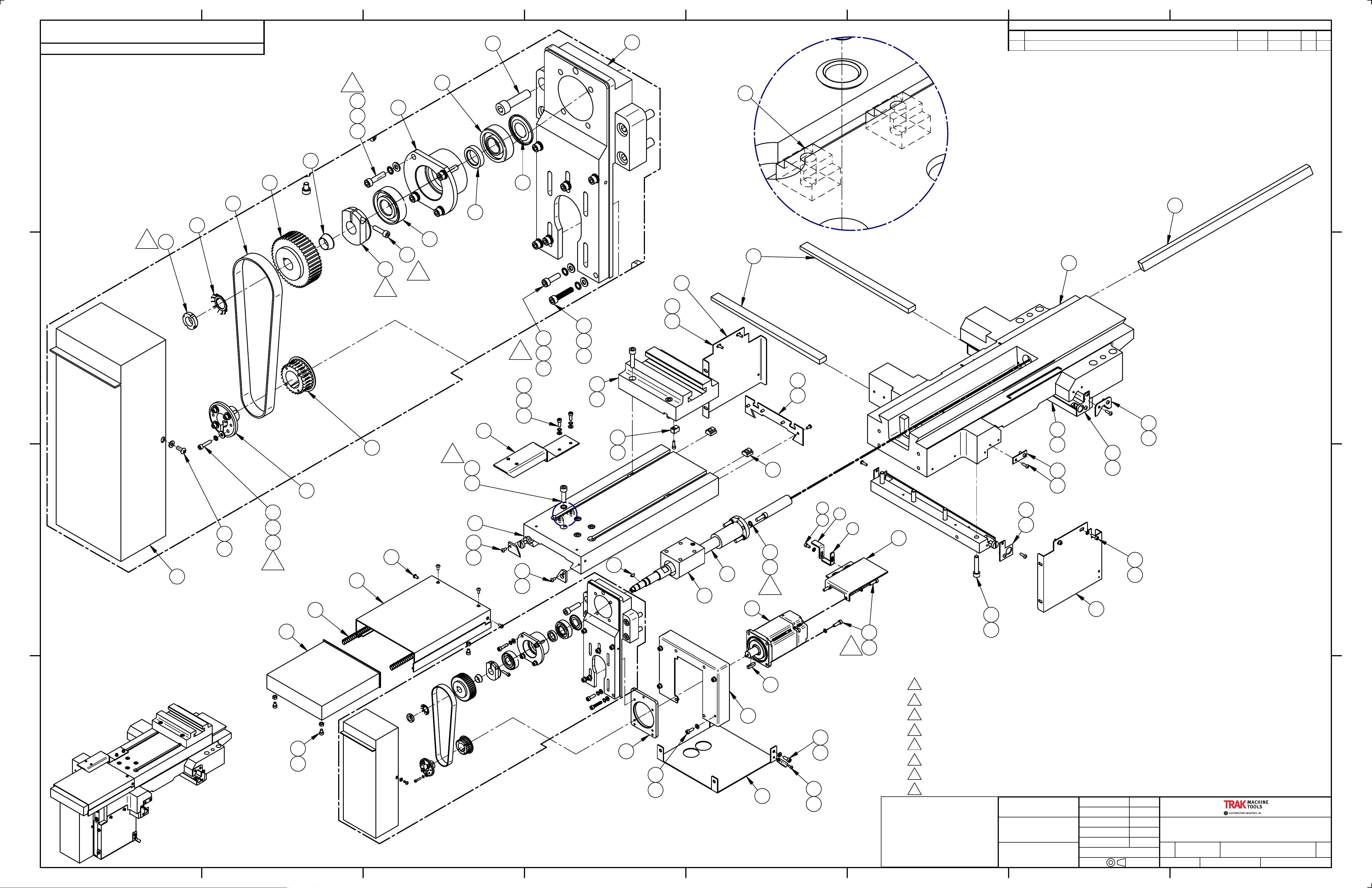
NOTICE: THIS DESIGN WAS ORIGINATED BY AND EMBODIES A CONFIDENTIAL PROPRIETARY DESIGN
OWNED BY SOUTHWESTERN INDUSTRIES. IT IS DISCLOSED IN CONFIDENCE FOR A SPECIFIC PURPOSE
AND THE RECIPIENT HEREOF AGREES NOT TO MAKE ANY REPRODUCTION, DISCLOSURE OR OTHER USE
OF THIS INFORMATION WITHOUT THE WRITTEN CONSENT OF SOUTHWESTERN INDUSTRIES.
© SOUTHWESTERN INDUSTRIES, INC. 2018 ALL RIGHT RESERVED
12345678
REVISIONS
REV
88(4X)
1 REF
PRODUCTION RELEASE
A
ECN DATE DFTDESCRIPTION
14959
02/06/19
AC
ENG
LG
D
6
15
14
13
12
11
7
7
692X
794X
6
1054X
984X
D
5
45REF
6 REF
DETAIL B
7
C
26
8
1
112
2
8
68
44(2X)
35REF
40REF
81(2X)
96(2X)
C
4
84 3X
105 3X
85 (4X)
105 (4X)
98 (4X)
98 3X
772X
1052X
64REF
89(4X)
56 REF
80 (4X)
982X
58 (2X)
90 (4X)
65(2X)
82 (4X)
42 REF
81(2X)
53 (2X)
B
DETAIL A
37 REF
76 2X
95 2X
111 4X
118 4X
117 4X
3
60REF
27
87(4X)
104(4X)
B
36REF
80REF
62 (4X)
83
96
28
29
57 (2X)
82 (4X)
52 (2X)
82 (4X)
24 REF
86 4X
80REF
54REF
10
80REF
2
103 4X
82 (4X)
B
81 (2X)
96 (2X)
59REF
55REF
5
3 REF
61(2X)
22REF
39 REF
90 (4X)
84 4X
43 REF
A
ISO VIEW
105 4X
4
NOTES: (UNLESS OTHERWISE SPECIFIED).
25 REF
38 REF
1 TORQUE CLAMP NUT (ITEM 8) TO 50 FT-LBS (C6)
2 TORQUE 10-32X3/4 25B SCREW (ITEM 112) TO 7.5 FT-LBS OR 90 IN-LBS (C6).
3 TORQUE 6-32X5/8 25B SCREWS (ITEM 111) TO 22 IN-LBS IN A CROSSING PATTERN (B7).
4 TORQUE M6-1.0X20 25B SCREWS (ITEM 84) THAT FASTENS TO MOTOR ADAPTER (ITEM 21) TO 5 FT LBS OR 60 IN LBS (B4, C6).
77 (2X)
5 TORQUE M8-1.25X25 25B SCREWS (ITEM 86) TO 25 FT-LBS (B4)
78(4X)
21REF
96 (2X)
101(4X)
77(4X)
76
66
DIMENSIONS ARE IN INCHES
DEC. .X = ±.1, .XX = ±.01, .XXX =
REMOVE ALL SHARP EDGES
MASK ALL TAPPED HOLES
DIMENSIONING PER ASME Y14.5
A
98(4X)
41 REF
6 TORQUE N02 LOCKNUT (ITEM 15) TO 20 FT-LBS (A8)
7 TORQUE M6-1.0X25 25B SCREWS (ITEM 79) TO 10 FT-LBS OR 120 IN-LBS (D7)
8 TORQUE M10-1.5X35 25B SCREWS (ITEM 87) TO 25 FT-LBS (B5)
DATEAPPROVALS
±.005,
ANGLES .XX = ±0°30'
FRACTIONS = ±1/8
FINISH = 125 RMS
MATERIAL
FINISH
DRAWN BY
ENGINEER
CHECKER
FE
THIRD ANGLE PROJECTION
AC
LG
JJ
01/31/18
01/31/18
TITLE
DRIVE ASSY - X AXIS - 1845RX
SIZE
SCALE:
CODE IDENT. NO. DWG NO. REV
D
06238
29533
SHEET 1 OF 1
A
A
12345678
Page 100
Parts List for Assembly P/N: 29533
Printed 1/31/2019
29533
DRIVE ASSY - X AXIS - 1845RX
1845
Type
Revision
Status
Date
By
PL
A
R
2/23/2017
DSM
Dwg Size
Product
Engineer
Planner Code
Comm Code
1845
DSM
Item P/N Title Detail Reference(t) Qty UseAs Rev Stat Type
1 29527
BRACKET - MOTOR MOUNT - X AXIS -
(1) EA A R DWG
1845RX/2470RX
2 20984 BALLSCREW ASSY. X-AXIS (1) EA A R DWG
3 27985 YOKE-X AXIS (1) EA - R PS
5 7204-AVH NILOS RING-7204 1 EA R PS
6 16300 BEARING HOUSING ASSY-X AXIS 1 EA A R PL
7 23930 BEARING SET (2)-ANGULAR CONTACT-7204 BECBP 1 EA - R PL
8 16314 NUT CLAMP-X, Y, Z AXIZ 1 EA F R DWG
10 98481A090 KEY WOODRUFF #404-1/8 X 1/2 1 EA - R PS
11 16350 FERRULE-SPROCKET-DRIVE KIT 1 EA - R DWG
12 16983-1 PULLEY-SOLID 44 TEETH 1 EA D R DWG
13 535-5M-15 BELT - TIMING 5MM POWERGRIP 1 EA - R PS
14 W02 LOCKWASHER 1 EA R PS
15 N02 LOCKNUT 1 EA R PS
21 29421-1 ADAPTER PLATE-750W BRUSHLESS MOTOR (80MM) 1845/2470 (1) EA A R DWG
22 28164 MOTOR-BRUSHLESS-DELTA-750W ECMA-C20807RS (1) EA D R PL
24 29440-3 BRACKET-CLAMP-MOTOR CONNECTOR 1845 (1) EA A R DWG
25 29433-1 KEY-80MM FRAME MOTOR (1) EA A R PS
26 29430 PULLEY ASSY-26 TOOTH-15MM WIDE-19MM BORE 1 EA A R PL
27 29431-1 TAPER LOCK-19MM BORE 1 EA A R DWG
28 29440-5 CLAMP-UPPER-MOTOR CONNECTOR 1 EA A R DWG
SOUTHWESTERN INDUSTRIES, INC.
29533
2615 HOMESTEAD PLACE, RANCHO DOMINGUEZ, CA. 90220
1-310-608-4422 Fax 1-310-764-2668
4Page 1 of
 Loading...