

Page 1
TRAK® 3ntr 3D Printers
SPFU Installation Quick Start Guide
Covers Current Models:
• 3ntr A2
• 3ntr A4
2615 Homestead Place
Rancho Dominguez, CA 90220-5610 USA
T | 310.608.4422 | F | 310.764.2668
Service Department: 800.367.3165
e-mail: [email protected] | [email protected] | web: www.trakmt.com
Document: P/N 32230
Version: 111919
Page 2

Copyright © 2019, Southwestern Industries, Inc. All rights are reserved. No part of this publication may
be reproduced, stored in a retrieval system, or transmitted, in any form or by any means, mechanical,
photocopying, recording or otherwise, without the prior written permission of Southwestern Industries,
Inc.
While every effort has been made to include all the information required for the purposes of this guide,
Southwestern Industries, Inc. assumes no responsibility for inaccuracies or omission and accepts no
liability for damages resulting from the use of the information contained in this guide.
All brand names and products are trademarks or registered trademarks of their respective holders.
Southwestern Industries, Inc.
2615 Homestead Place
Rancho Dominguez, CA 90220
Phone 310-608-4422 Fax 310-764-2668
Service Department
Phone 800-367-3165 Fax 310-886-8029
Page 3

i
TRAK Machine Tools
Southwestern Industries, Inc.
TRAK 3ntr 3D Printers – SPFU Installation Quick Start Guide
Table of Contents
1 Introduction ............................................................... 1
2 Clean Nozzle Procedure .............................................. 1
2.1 Clean Nozzle Procedure Overview: ....................................................... 1
2.2 Unload Filament Using Change Filament Function ............................... 1
2.3 Load Cleaning Filament ........................................................................ 5
2.4 Nozzle Cleaning (Automated Function) ................................................ 7
3 Install SPFU to Nozzle #1 .........................................11
4 TRAK Warranty Policy ...............................................20
Page 4

1
TRAK Machine Tools
Southwestern Industries, Inc.
TRAK 3ntr 3D Printers – SPFU Installation Quick Start Guide
1 Introduction
This guide outlines the process to install the Soft Polymer Feeder Unit (SPFU) to Nozzle #1 of your TRAK
3ntr A2 or A4 printer. Before you can install the SPFU, you must complete the Clean Nozzle procedure
(also outlined within this guide).
2 Clean Nozzle Procedure
This section details all the steps to clean extruder nozzles. The nozzle cleaning procedure must ALWAYS
be performed BEFORE changing to a new polymer type filament. A nozzle cleaning procedure should
always be performed any time there are unacceptable nozzle flow conditions that cannot be cleared with
several purge cycles.
2.1 Clean Nozzle Procedure Overview:
There are three steps to cleaning nozzles;
1) Remove existing filament(s) using the change filament function
2) Feed cleaning filament (nylon) to the extruder(s)
3) Clean nozzle(s) using the front panel control Clean Nozzle function
CAUTION - Only load factory recommended (nylon or equivalent) filament for cleaning procedures.
NOTE - Before using the Clean Nozzle function from the front panel, you must use the Change/Load
Cleaning Filament procedure to remove build/support filament and feed the nylon cleaning filament to the
extruders to be cleaned.
2.2 Unload Filament Using Change Filament Function
In this section, you will change filament removing existing spools before installing the cleaning filament
(instead of a new build/support material filament spool). It should always be performed before a nozzle
cleaning procedure.
NOTE - If you are using an MMS unit or PolyBox (humidity-controlled container) the process is different.
If feeding material directly from a PolyBox or equivalent container, follow the instructions as applicable
1) Check that there is enough clearance (20-30mm) between nozzle and plate before starting. If
not, move printer plate following instructions for “Move Z axis function”
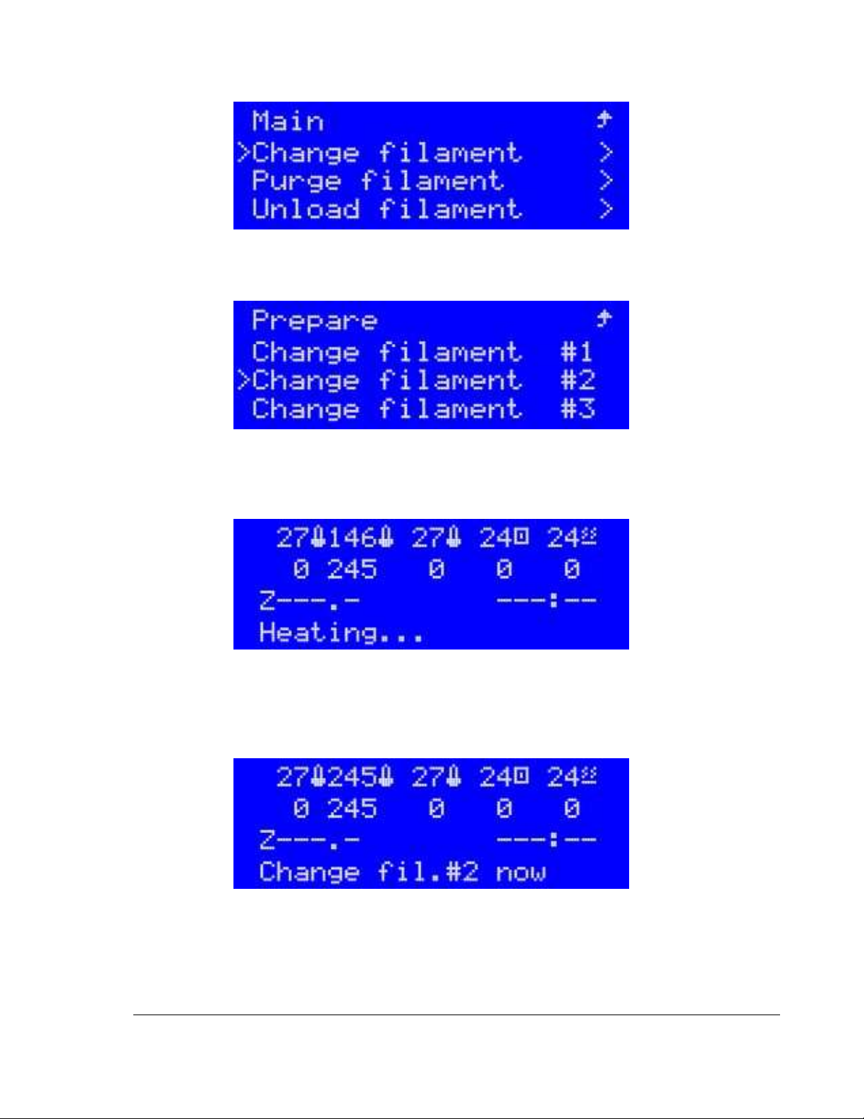
2) Navigate to the Prepare menu. From the Prepare menu select “Change filament”
Page 5
2
TRAK Machine Tools
Southwestern Industries, Inc.
TRAK 3ntr 3D Printers – SPFU Installation Quick Start Guide
Figure 2.2.1 Selecting Change Filament from Prepare Menu
3) Assuming filament has been previously loaded, Select Change Filament “Extruder #1”
Figure 2.2.2 Selecting Extruder for Change Filament
4) The selected extruder will begin heating up and the LCD will display Heating… Observe the
temperature readout for the selected extruder and see it increasing.
Figure 2.2.3 Info Display During Change Filament
5) Once the set temperature is reached, the machine will purge some filament. Once this automatic
purging is completed, the display will indicate “Unload Filament Now”. At this time, you can now
reach to the back of the cabinet to unload the filament.
Figure 2.2.4 Printer Readiness Signal to Change Filament Spool
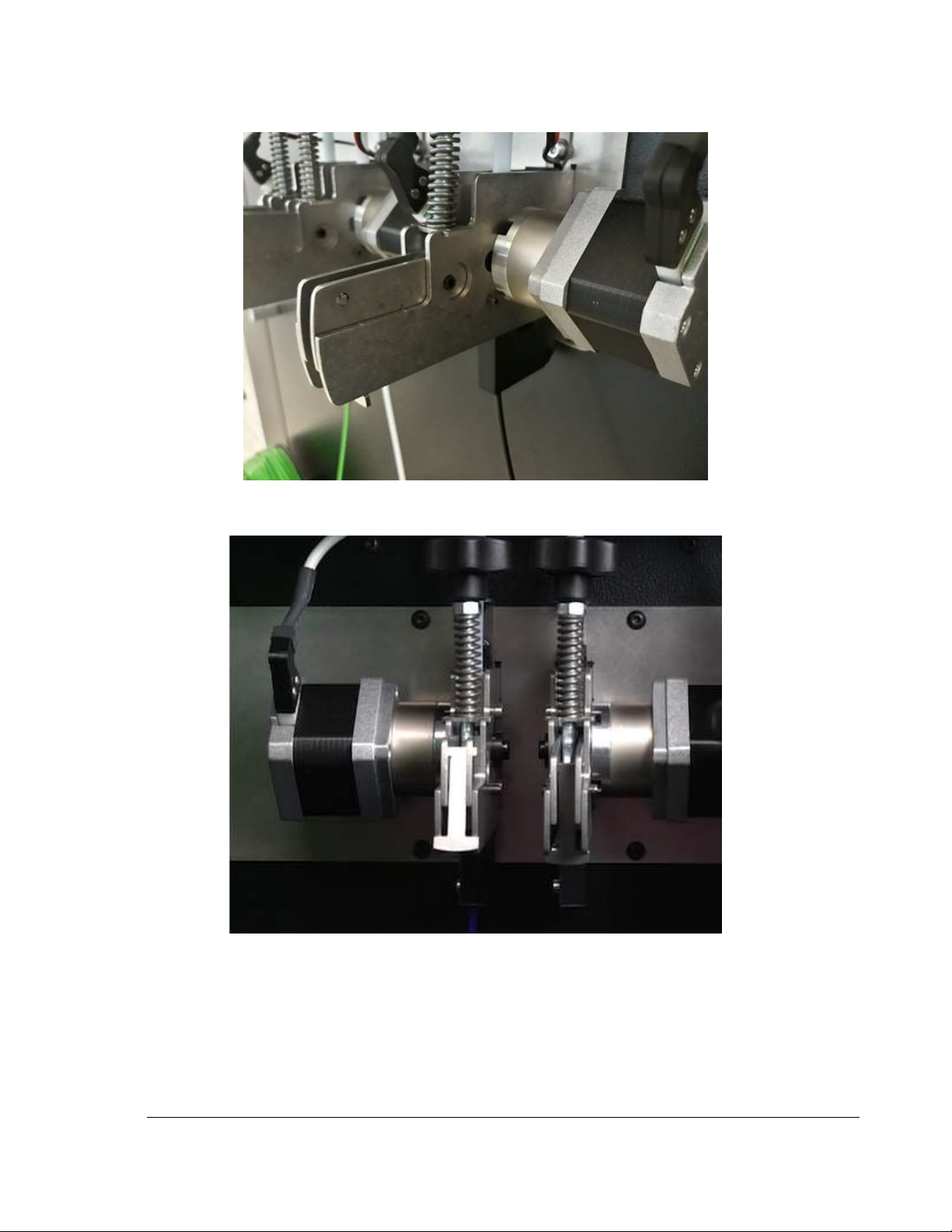
6) Locate the feeder handle on the selected extruder. Grab the feeder handle of the selected
extruder, push it down and secure it into position with the provided lock “lip” This way the feeder
mechanism will be disengaged. Looking at the feeders from the rear of the printer, the rightmost
is the #1 feeder, and leftmost is #3.
Page 6
3
TRAK Machine Tools
Southwestern Industries, Inc.
TRAK 3ntr 3D Printers – SPFU Installation Quick Start Guide
Figure 2.2.5 Disengage filament feeder
Figure 2.2.6 Latched & Unlatched Filament Feeders
Page 7
4
TRAK Machine Tools
Southwestern Industries, Inc.
TRAK 3ntr 3D Printers – SPFU Installation Quick Start Guide
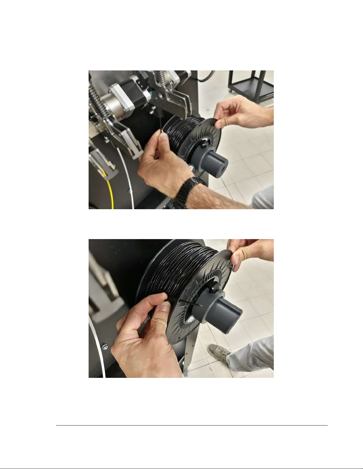
7) Pull the filament from the feeder, rewinding the filament onto the spool.
Figure 2.2.7 Pulling old filament out of feeder unit
8) Thread the end through the opening on the spool to keep it from de-coiling.
Figure 2.2.8 Secure filament end to spool
9) Unlock and remove collar from filament spool spindle of selected extruder on back of printer.
Remove filament spool and place in a dry and clean container (with desiccant package) away
from heat and sunlight.
Page 8
5
TRAK Machine Tools
Southwestern Industries, Inc.
TRAK 3ntr 3D Printers – SPFU Installation Quick Start Guide
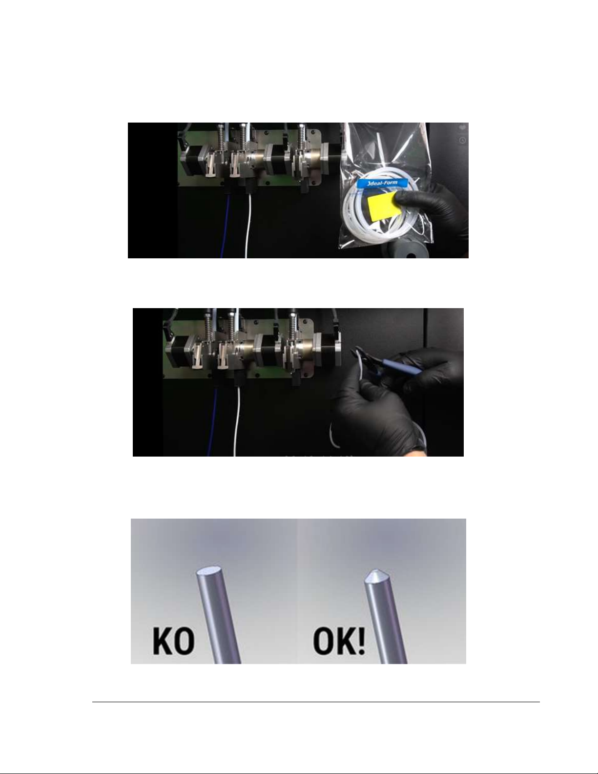
2.3 Load Cleaning Filament
1) Obtain the cleaning filament (Hollow nylon filament specially for nozzle cleaning).
Figure 2.3.1 Nozzle Cleaning Filament (Nylon)
2) Trim off several mm to remove bends, dirt, tape, or damage. Straighten as needed.
Figure 2.3.2 Trim off the end of new filament
3) Use scissors, knife, or a pencil sharpener to point the filament end for easy feeding to the
extruder.
Figure 2.3.3 Illustration of correct and incorrect filament tip sharpening
Page 9
6
TRAK Machine Tools
Southwestern Industries, Inc.
TRAK 3ntr 3D Printers – SPFU Installation Quick Start Guide
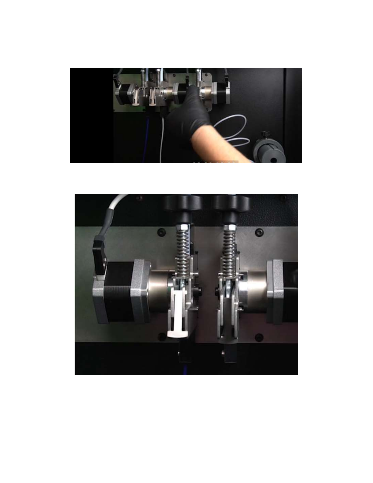
4) Feed the filament into the feeder unit and keep feeding until the end stops at the extruder.
Release the feeder handle. Verify the locking “lip” is disengaged.
Figure 2.3.4 Engage the filament feeder
5) The locking lip is now engaged. The machine will automatically control the filament feed.
Figure 2.3.5 Latched and Unlatched Filament Feeders
Page 10
7
TRAK Machine Tools
Southwestern Industries, Inc.
TRAK 3ntr 3D Printers – SPFU Installation Quick Start Guide
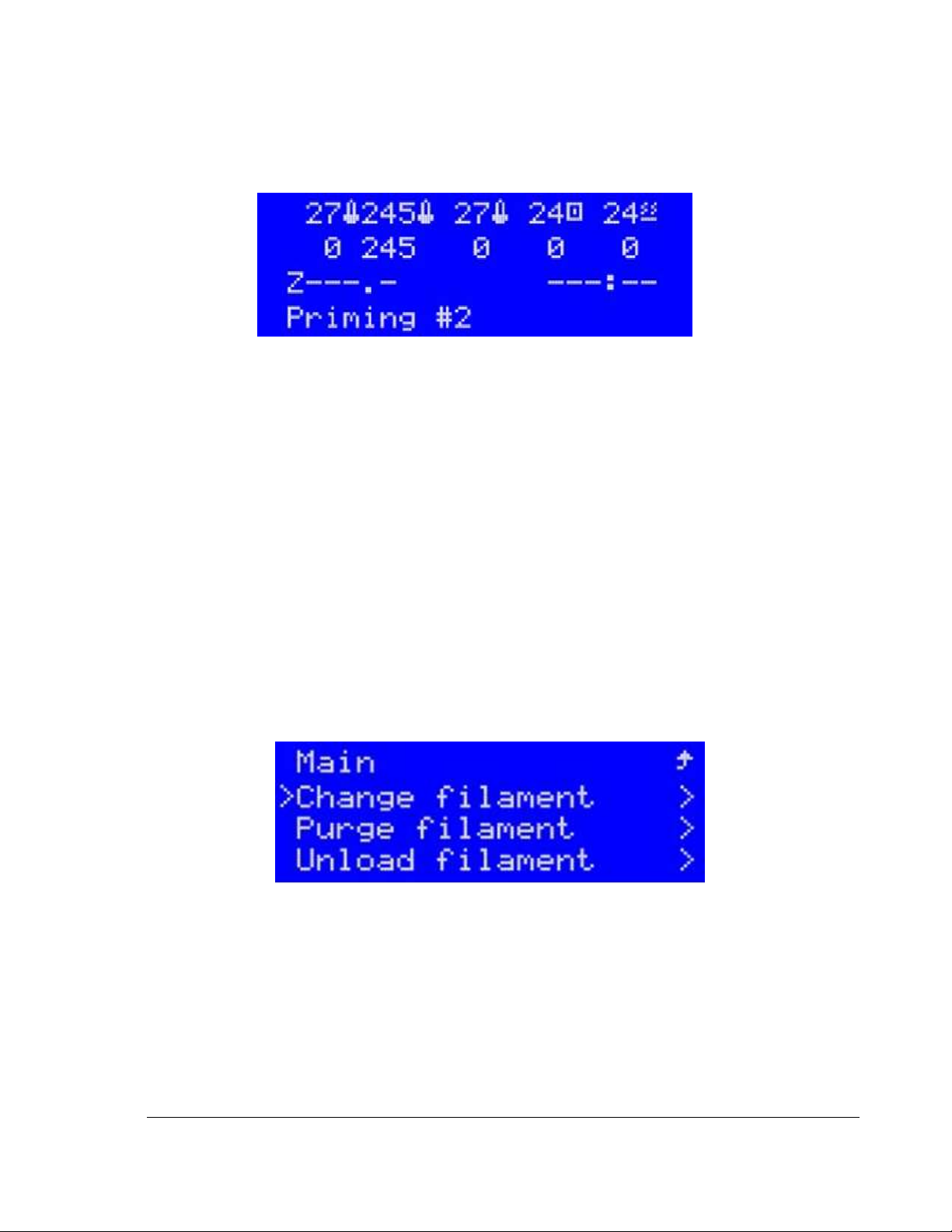
6) Press the button on the jog wheel. The LCD will display “Priming #X” as it purges some filament.
Upon completion, the LCD will display “Change #x Complete” to indicate completion.
Figure 2.3.6 LCD Display while new filament is priming
7) Repeat filament change/load cleaning filament procedure for extruder #2 (as necessary)
8) Repeat filament change/load cleaning filament procedure for extruder #3 (as necessary)
9) Procedure complete!
2.4 Nozzle Cleaning (Automated Function)
This section details the nozzle cleaning procedure. The nozzle cleaning procedure must ALWAYS be
performed BEFORE changing to a new polymer type filament. A nozzle cleaning procedure should always
be performed any time there are unacceptable nozzle flow conditions that cannot be cleared with several
purge cycles.
NOTE - Before using the Clean Nozzle function from the front panel, you must use the Change Filament
procedure to remove build/support filament and feed the nylon cleaning filament to the extruders to be
cleaned.
1) Use CHANGE FILAMENT/Load Cleaning Filament procedure (see appropriate guide section for
instructions) to remove filament in use and to load cleaner filament to the machine.
Figure 2.4.1 Change Filament Function
Page 11
8
TRAK Machine Tools
Southwestern Industries, Inc.
TRAK 3ntr 3D Printers – SPFU Installation Quick Start Guide
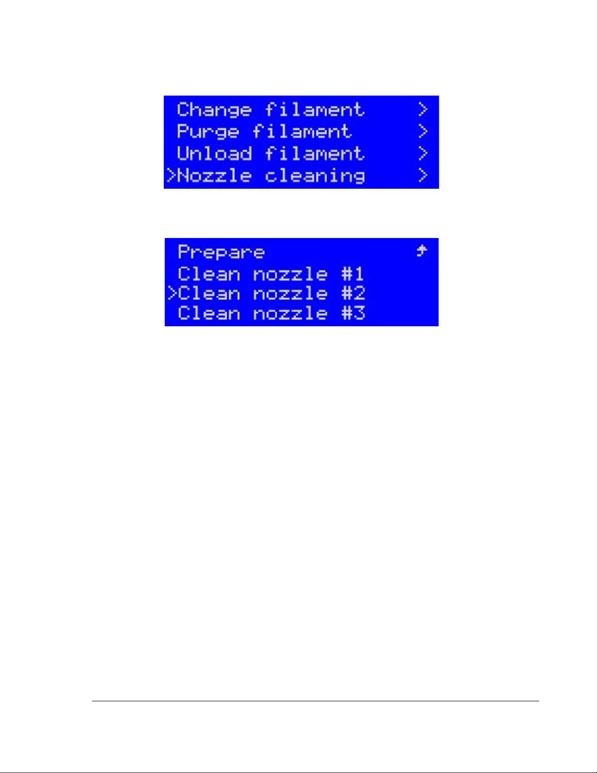
2) Select the nozzle cleaning function from the printer control panel Prepare Menu
Figure 2.4.2 Prepare Menu: Nozzle Cleaning Selected
3) Choose the nozzle to be cleaned (Nozzle #2 in this example)
Figure 2.4.3 Select Extruder for Cleaning
Page 12
9
TRAK Machine Tools
Southwestern Industries, Inc.
TRAK 3ntr 3D Printers – SPFU Installation Quick Start Guide
4) After verifying the nylon cleaning filament is properly loaded into the extruder, press the black
jog wheel button to start the automatic cleaning procedure.
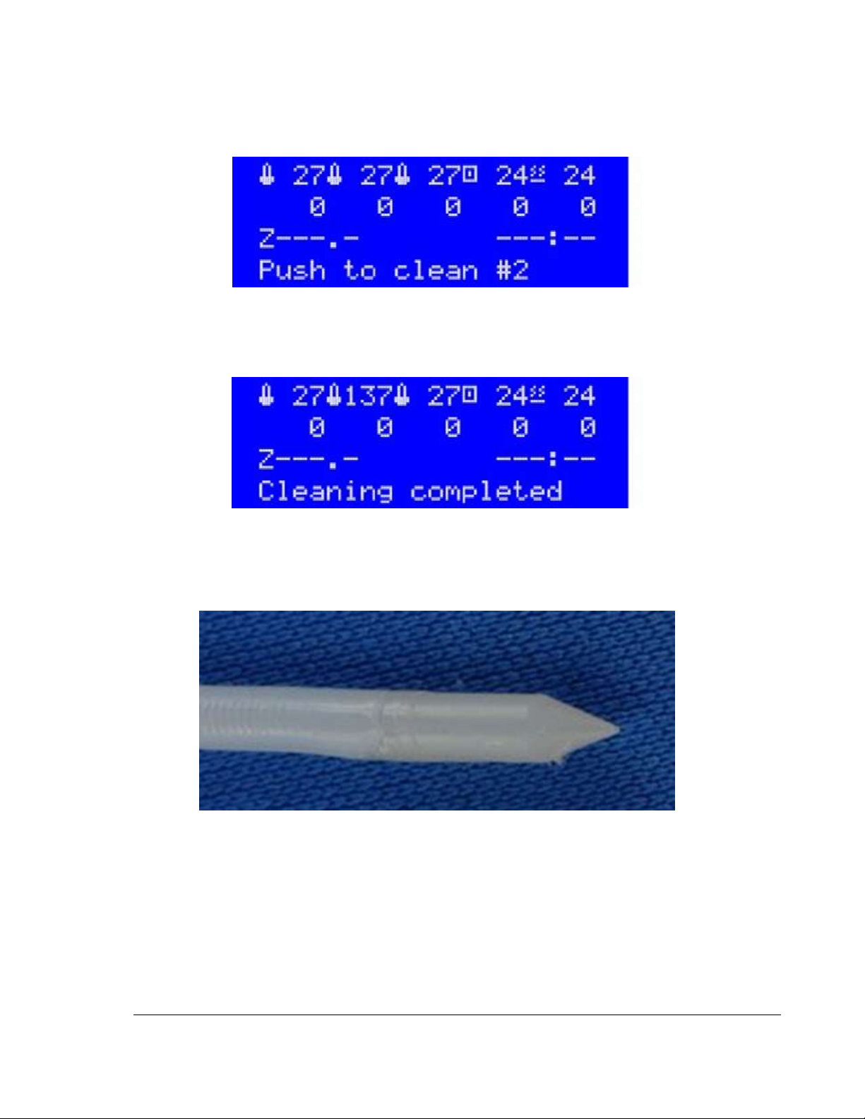
Figure 2.4.4 Printer indication – Ready to Clean
5) The printer will now heat the chosen extruder, clean the nozzle, then cool it down to a preset
value and pulls out the filament (from the heated nozzle) for you to check it.
Figure 2.4.5 LCD Indicating Cleaning Complete
6) Inspect the cleaning filament tip after the cleaning cycle.
7) If the filament tip appears with the proper shape and no traces of color, then the cleaning
process can be concluded, if not, additional steps are required (below)
Figure 2.4.6 Ideal Cleaning Filament Tip (after cleaning)
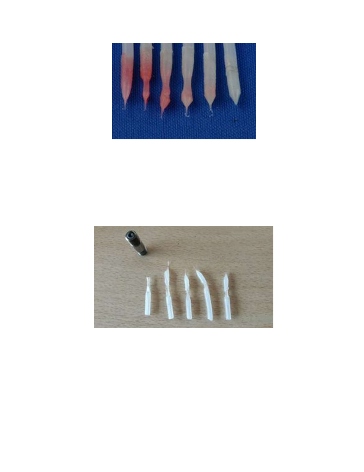
8) If the filament tip after cleaning has any traces of color on it (as below), repeat the cleaning
process for additional cycles, until no traces of color remain.
Page 13
10
TRAK Machine Tools
Southwestern Industries, Inc.
TRAK 3ntr 3D Printers – SPFU Installation Quick Start Guide
Figure 2.4.7 Cleaning Filament Tip Color after multiple Cleaning Cycles
9) If the shape of the extruded cleaning filament tip after the cleaning cycle is not ideal (as
pictured above), repeat the cleaning cycle a couple times.
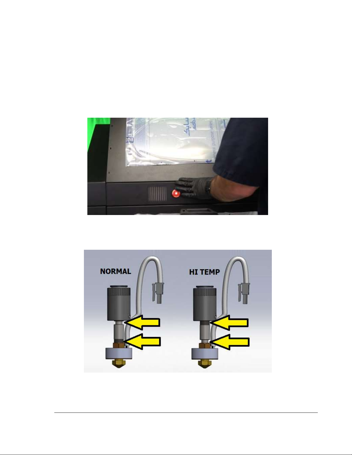
10) If an ideal cleaning filament tip is not obtained after a couple cycles (bad tips shown below),
perform the following extruder troubleshooting steps:
a. Check/Fill coolant liquid level
b. Verify coolant fluid flow to extruder
c. Check extruder thermal gain setting (correct if necessary)
d. Perform a Feeder roller cleaning procedure
e. Nozzle change (may be required)
Figure 2.4.8 Bad Tips after Filament Cleaning: Requires Troubleshooting
11) Repeat entire cleaning process for other extruders (as required/needed)
12) Nozzle cleaning function complete!
Page 14
11
TRAK Machine Tools
Southwestern Industries, Inc.
TRAK 3ntr 3D Printers – SPFU Installation Quick Start Guide
3 Install SPFU to Nozzle #1
This section outlines the process to install the SPFU on Nozzle #1. You must complete the Nozzle
Cleaning procedure before proceeding with SPFU installation.
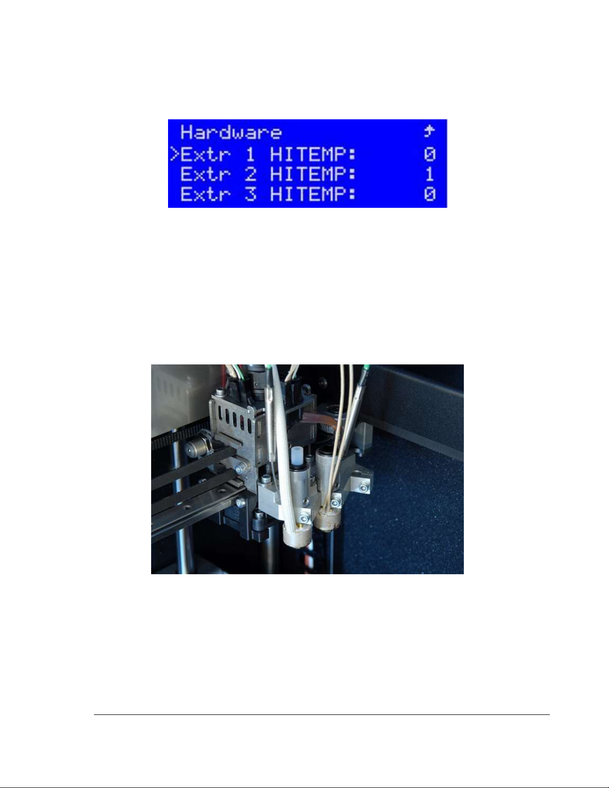
1) Move print bed away from extruders (for access) using Move Axis function.
2) Use a 2.5mm hex key to remove the screws holding the printer upper front panel cover (#1 in drawing
below). There are 8 screws on an A2, 4 screws on an A4.
3) Remove printer front access cover to provide access for installation.
Figure 3.1 Removing Printer Front Access Cover
4) Inspect the extruder #1 configuration visually within the printer. Verify extruder #1 is mounted in
the Normal position (see illustration below)
Figure 3.2 Extruder Configuration ID Guide: Normal and HI TEMP
Page 15
12
TRAK Machine Tools
Southwestern Industries, Inc.
TRAK 3ntr 3D Printers – SPFU Installation Quick Start Guide
5) Verify extruder #1 is set for NORMAL (not HI TEMP) control setting. Use the printer control panel
to go to Hardware>Extruder Configuration. Normal setting is indicated with HITEMP = 0
(Required for SPFU).
Figure 3.3 Extruder #1 in Normal Control Setting
6) Follow the Clean Nozzle procedure (See the appropriate guide section for instructions) to remove
current filament, feed cleaning material to extruder(s), and perform the automatic cleaning
function.
CAUTION – You must complete the Clean Nozzle procedure before continuing with the SPFU
fitment procedure. A Nozzle Cleaning procedure must be completed for each nozzle before SPFU
can be fitted.
7) Turn OFF Printer
8) Remove PTFE piping from #1 & #2.
9) Fit the 25mm PTFE pipe on #1 tube adapter
Figure 3.4 PTFE Piping for SPFU on Extruder
10) Remove the feeder for Extruder #1
Page 16
13
TRAK Machine Tools
Southwestern Industries, Inc.
TRAK 3ntr 3D Printers – SPFU Installation Quick Start Guide
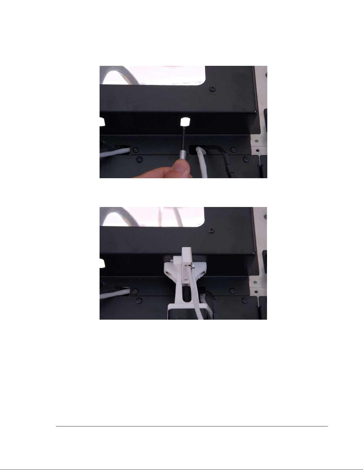
11) Feed the flexible shaft of the SPFU motor assembly through the passage of #1 piping
Figure 3.5 Shaft for SPFU
12) Put the motor assembly in place. Magnet will hold the part securely against the machine.
Figure 3.6 SPFU Motor Placement
13) Verify the printer power is OFF
NOTE -Never plug in stepper motor cables with power ON.
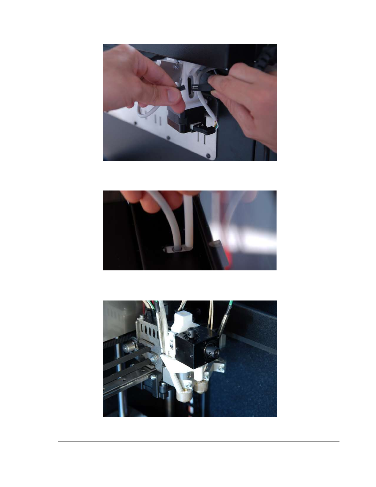
14) Connect stepper motor
15) Connect filament sensor
Page 17
14
TRAK Machine Tools
Southwestern Industries, Inc.
TRAK 3ntr 3D Printers – SPFU Installation Quick Start Guide
Figure 3.7 Connect Stepper Motor and Filament Sensor
16) Fit the PTFE piping into motor assembly as shown
Figure 3.8 Fitting PTFE piping into motor assembly as shown
17) Place SPFU on Extruder #1
Figure 3.9 SPFU Mounted on Extruder #1
Page 18
15
TRAK Machine Tools
Southwestern Industries, Inc.
TRAK 3ntr 3D Printers – SPFU Installation Quick Start Guide
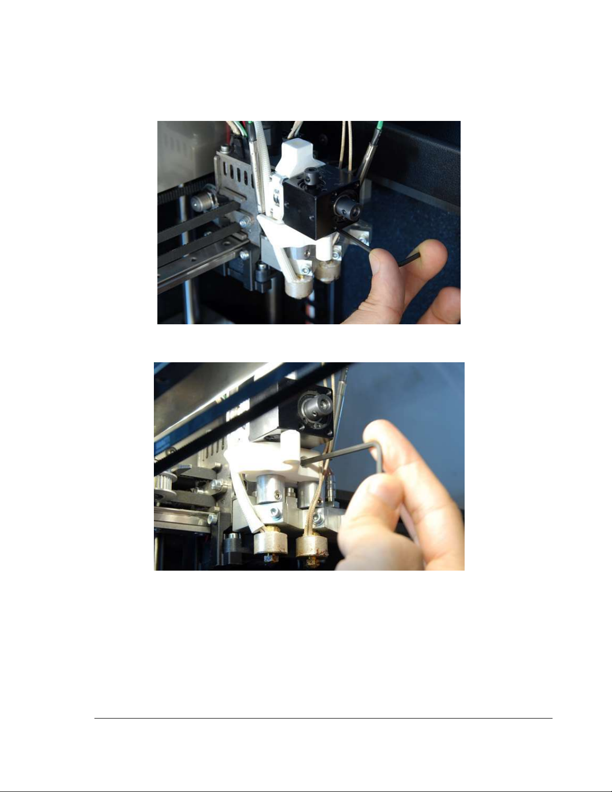
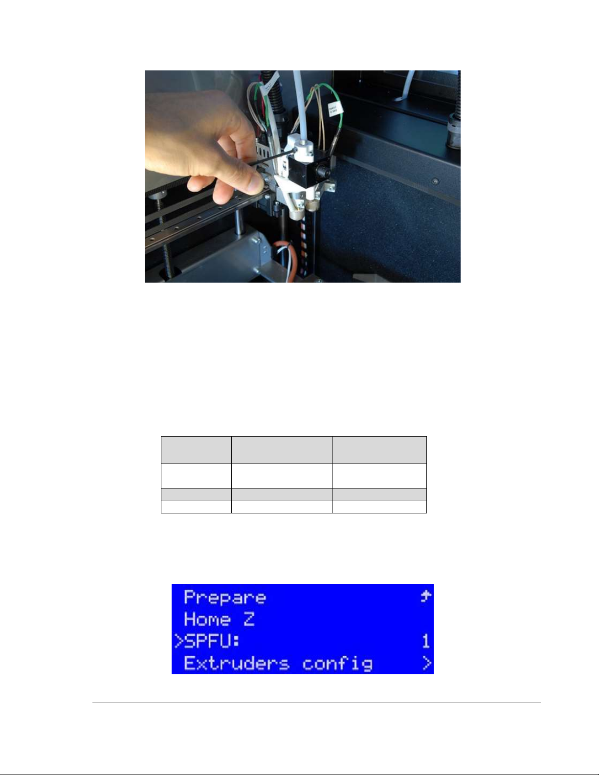
18) Tighten the locking screw on the SPFU assembly with an Allen wrench. Do not overtighten, snug
is acceptable. User should encounter resistance when lifting up on the SPFU
Figure 3.10 Tighten Locking Screw on SPFU Assembly
Figure 3.11 View of SPFU Locking Screw from below
Page 19
16
TRAK Machine Tools
Southwestern Industries, Inc.
TRAK 3ntr 3D Printers – SPFU Installation Quick Start Guide
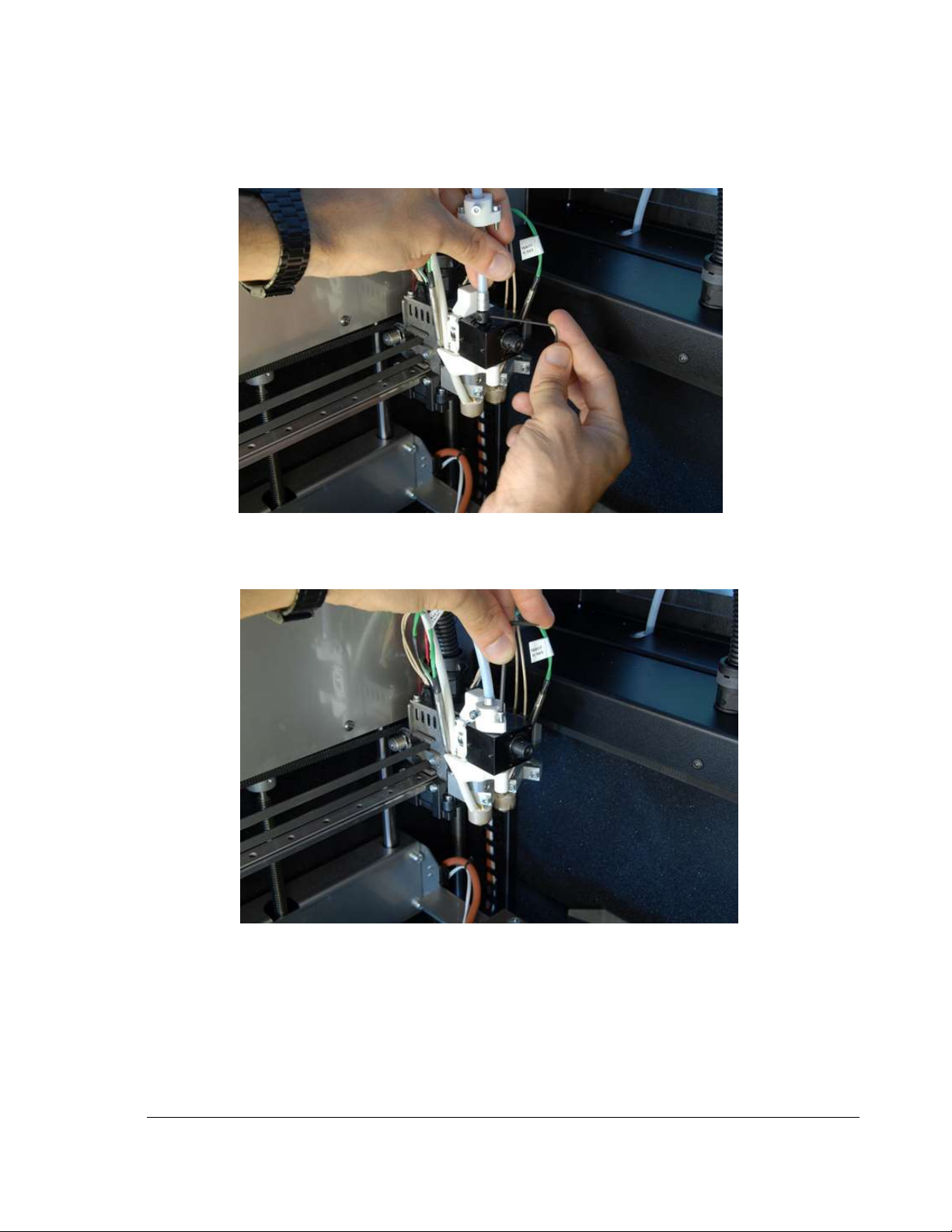
19) Place Flexible shaft as shown. Tighten the three set screws. Do not overtighten, snug is
acceptable.
Figure 3.12 SPFU Flexible Shaft Placement & Tightening
20) Tighten the shaft holder screws. Do not overtighten, snug is acceptable.
Figure 3.13 SPFU Shaft Holder Screw Tightening
21) Lock the flexible shaft. Tighten until driveshaft tube is snug.
NOTE – Be sure the shaft is fully seated, and screw is acting against end of the shaft piping.
There may not be an aluminum component on the end of the shaft (as in illustration).
Page 20
17
TRAK Machine Tools
Southwestern Industries, Inc.
TRAK 3ntr 3D Printers – SPFU Installation Quick Start Guide
Figure 3.14 Locking SPFU Flexible Shaft
22) Power ON the Printer.
NOTE – Printer can be powered ON once the feeder disconnect and SPFU feeder connect are
done. This will provide chamber lighting.
23) Determine the desired SPFU enablement mode for your installation based on the table below.
The mode selected depends on the location of the SPFU installation (Front/Extruder #1 or
Rear/Extruder #3) and if Chamber Heating is to be enabled or disabled.
NOTE – Chamber Heating is often disabled with an SPFU installation to avoid accidentally melting
the polymer within the feeder tube/SPFU unit. If you choose one of the SPFU modes with
enabled chamber heating, be sure to set chamber heating temperatures to an acceptable (lower)
temperature.
SPFU Mode
Setting
SPFU Installation
Location
Chamber Heater
Enablement
1
Front – Extruder #1
Disabled
2
Rear – Extruder #3
Disabled
3
Front – Extruder #1
Enabled
4
Rear – Extruder #3
Enabled
NOTE – For a front/Extruder #1 SPFU install, SPFU Mode Setting 3 is most typical.
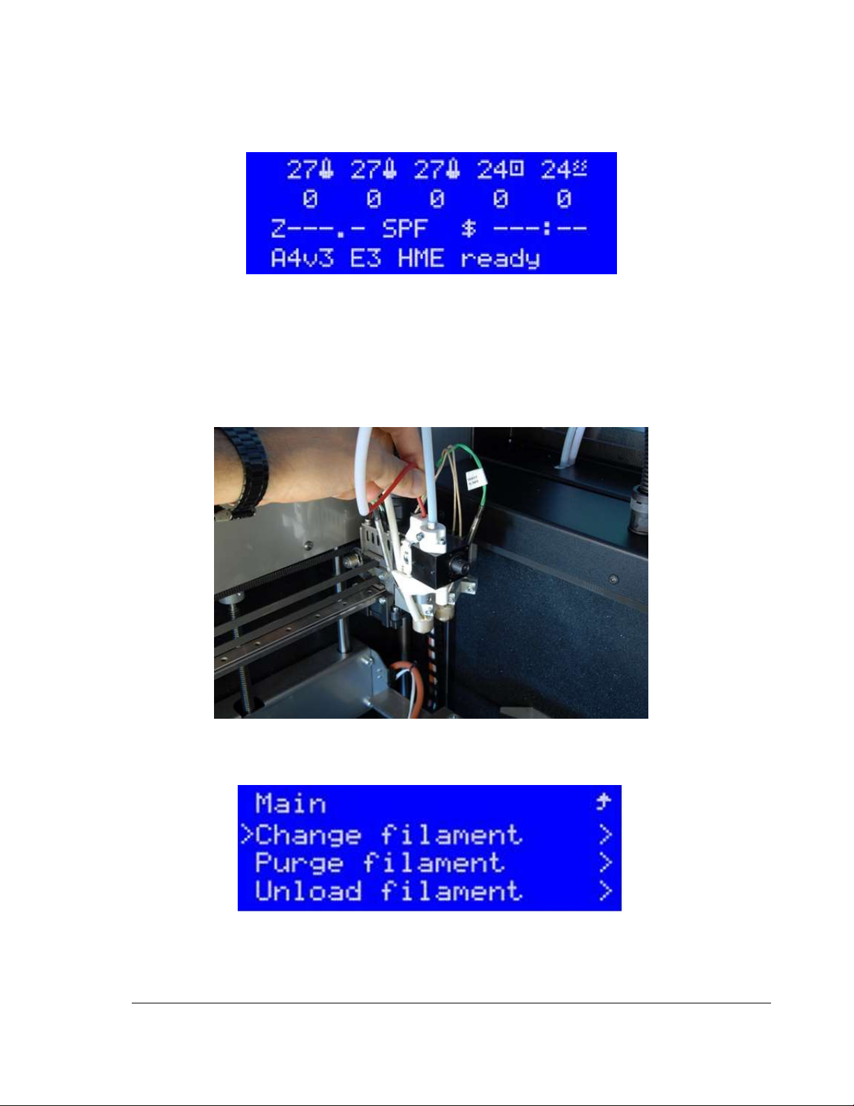
24) Navigate from the Printer LCD display. Go to Hardware >SPFU. Enable the SPFU from the front
control panel using the desired SPFU mode selection (from chart Above). Save.
Figure 3.15 Enabling SPFU from Hardware Menu
Page 21
18
TRAK Machine Tools
Southwestern Industries, Inc.
TRAK 3ntr 3D Printers – SPFU Installation Quick Start Guide
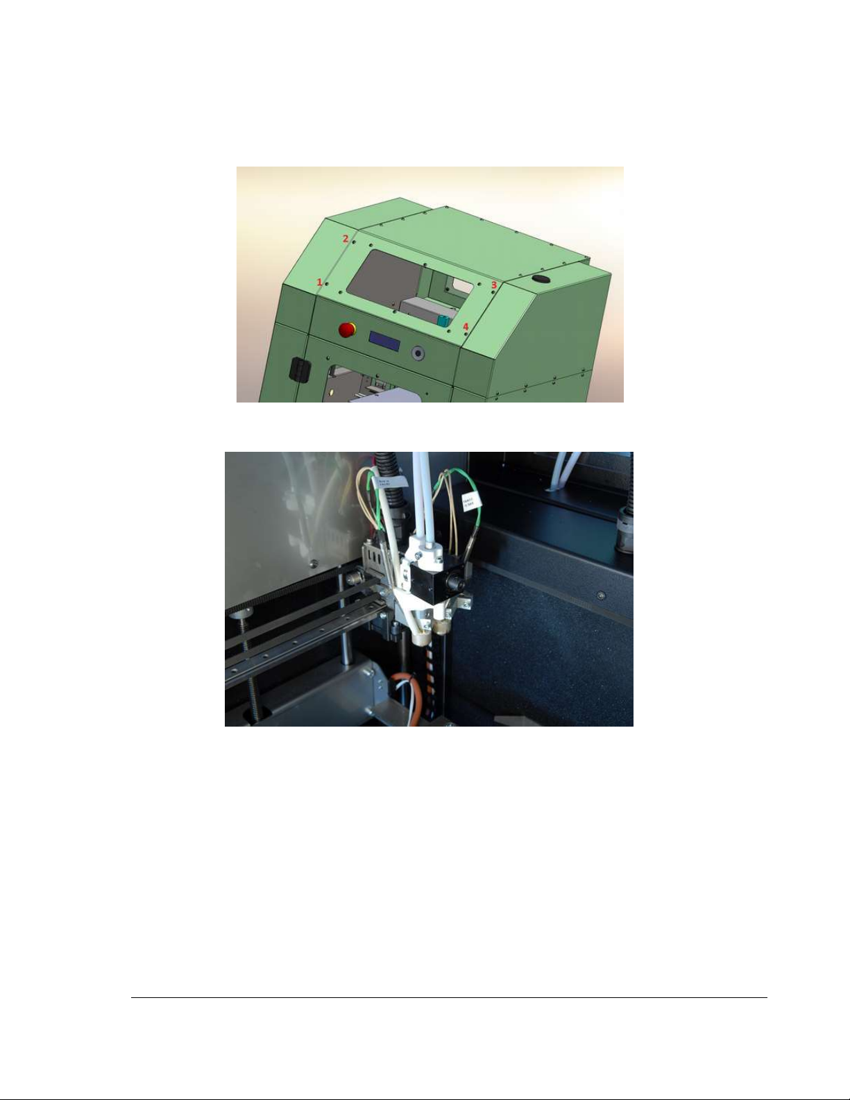
25) Verify SPFU is enabled by info screen display indicating “SPF”
Figure 3.16 Info Screen Indicating SPFU Enabled
26) Feed filament into filament feeder until it appears at the SPFU filament feed tube end.
NOTE – When feeding soft filament, it can be useful to ensure there is extra filament available
for feeding it into the SPFU/extruder.
27) Feed filament directly through the PTFE piping and into the SPFU unit until the pinch roller grabs
it. Carefully pull excess slack from the back of printer to set filament feeder tube properly.
Figure 3.17 Feeding Filament through PTFE piping
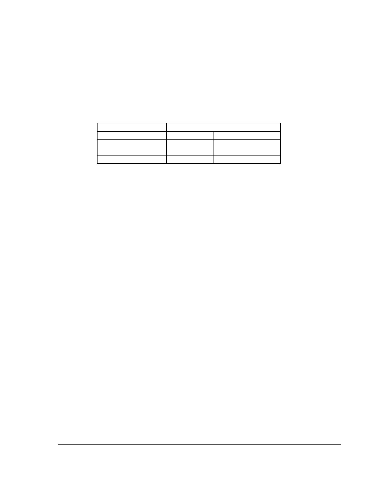
28) Perform the Filament Change function from the printer front panel and follow the on-screen
instructions to complete the process.
Figure 3.18 Change Filament Function
29) Connect the other end of the PTFE piping. Make sure it is firmly seated into SPFU
Page 22
19
TRAK Machine Tools
Southwestern Industries, Inc.
TRAK 3ntr 3D Printers – SPFU Installation Quick Start Guide
30) Replace Printer front upper access cover. Re-install and tighten screws with 2.5mm hex key.
There are 8 screws on an A2, 4 screws on an A4.
CAUTION – Never use printer without front access panel (or any access cover) removed.
Figure 3.19 Printer Front Access Cover and Screws
31) SPFU Installation process complete!
Figure 3.20 Completed SPFU Installation on Extruder #1
Page 23
20
TRAK Machine Tools
Southwestern Industries, Inc.
TRAK 3ntr 3D Printers – SPFU Installation Quick Start Guide
4 TRAK Warranty Policy
Southwestern Industries, Inc
Warranty
TRAK products are warranted to the original purchaser to be free from defects in workmanship and
materials for the following periods:
Product
Warranty Period
Materials
Factory Labor
New
TRAK/ProtoTRAK
1 Year
1 Year
Any EXCHANGE Unit
90 Days
90 Days
The warranty period starts on the date of the invoice to the original purchaser from Southwestern
Industries, Inc. (SWI) or their authorized distributor.
If a product, subsystem or component under warranty fails, it will be repaired or exchanged at our option
for a properly functioning unit in similar or better condition. Such repairs or exchanges will be made FOB
Factory/Los Angeles or the location of our nearest factory representative or authorized distributor.
Disclaimers of Warranties
• This warranty is expressly in lieu of any other warranties, express or implied, including any
implied warranty of merchantability or fitness for a particular purpose, and of any other obligations
or liability on the part of SWI (or any producing entity, if different).
• Warranty repairs/exchanges do not cover incidental costs such as installation, labor, freight, etc.
• SWI is not responsible for consequential damages from use or misuse of any of its products.
• TRAK products are precision mechanical/electromechanical/electronic systems and must be
given the reasonable care that these types of products require.
• Accidental damage, beyond the control of SWI, is not covered by the warranty. Thus, the
warranty does not apply if a product has been abused, dropped, hit or disassembled.
• Improper installation by or at the direction of the customer in such a way that the product
consequently fails, is considered to be beyond the control of the manufacturer and outside the
scope of the warranty.
Rev 091514
 Loading...