

Trajan 125 Instructions For Use And Maintenance / Spare Parts

PORTABLE BAND SAWING
INSTRUCTIONS FOR USE AND MAINTENANCE / SPARE PARTS
MODEL: 125
125-080605-R1

WARNING
!!
Some dust created by power sanding, sawing,
grinding, drilling, and other construction activities
contains chemicals known to the State of California to
cause cancer, birth defects or other reprodrctive harm.
Some examples of these chemical are:
‧Lead from lead-based paints.
‧Crystalline silica from bricks, cement and other
masonry products.
‧Arsenic and chromium from chemically-treated
lumber.
Your risk from these exposures varies, depending on
how often you do this type of work. To reduce your
exposure to these chemicals: Work in a well ventilated
area, and word with approved safety equipment, such
as those dust masks that are specially designed to
filter out microscopic particles.
4
Fig.Abb.6
F
Fig-Abb.8
F
5
5
1
7
2
5
7 U
8
8
Fig.-Abb.2
Fi
9
10
6
4
11
12
13
g
.-Abb.3 Fig.-Abb.1
K
J
I
H
M
L
G
E
Fig-Abb.6Fig-Abb.5
A
B
Fig-Abb.4
B
Q
R
D
P
S
Fig-Abb.9
Q
P
Fig-Abb.7 Fig-Abb.8 Fig-Abb.9
D
N
O
D
F
Fig.-Abb.1 Fig.-Abb.3
Fig.-Abb.6 Fig.-Abb.5 Fig.-Abb.4
Fig.-Abb.9
Fig.-Abb.8 Fig.-Abb.7
1

INDEX
CAUTION
Install saw blade and blade guard
before use. Set proper blade tension
Pag.
1.0 INTRODUCTION TO USE...............................2
1.1 SYMBOLS PLACED IN
CORRESPONDANCE WITH USAGE
POINTS .......................................................2
to prevent any danger caused by
damaged saw blade or work piece.
1.2 SAFETY AND RULES..................................2
1.3 RECOMMENDED AND NOT
RECMMENDED USAGE.............................3
1.0 INTRODUCTION TO USE
1.4 STANDARD SAFETY PROCEDURS...........3
1.5 SAFETY PROCEDURS FOR FURTHER
RISKS..........................................................3
Before starting work with your sawing machine, carefully
read this instructions manual so that you are familiar with
the machine and its uses and where it should not be used.
Keep this manual in a safe place.
1.6 NOISE CONDITION .....................................3
1.7 INFORMATION ABOUT THE
ELECTROMAGNETIC COMPTIBILITY ......3
It is an integral part of the machine and should be used for
reference in operating the machine correctly and in the
proper safety conditions.
1.8 DESCRIPTION OF THE MACHINE.............3
2.0 INSTALLATION...............................................3
2.1 REMOVING THE PACKAGING ...................3
Use the machine only and exclusively for the uses
specified below, as recommended in this manual. The
machine should not in any way be tampered with, or
forced, or used for unsuitable purposes.
2.2 HANDLING...................................................4
2.3 TRANSPORTATION.....................................4
2.4 POSITION/WORK STATION........................4
2.5 ELECTRICAL CONNECTION......................4
3.0 ADJUSTMENT.................................................4
1.1 SYMBOLS PLACED IN CORRESPONDANCE
3.1 TENSION OF THE BLADE...........................4
WITH USAGE POINTS
3.2 BAR STOP....................................................4
Never underestimate the warnings “ ATTENTION –
CAUTION ” given in this manual.
3.3 CUTTING ANGLE.........................................4
3.4 CUTTING SPEED.........................................4
In order to draw the user’s attention and to preserve safety,
hazardous operation are preceded by symbols and notes
that point out the danger and explain how to behave to
avoid any risk.
3.5 SLIDING BLADE GUIDE..............................4
3.6 BEARINGS BLADE GUIDE..........................5
4.0 USE..................................................................5
4.1 RUNNING-IN THE BLADE...........................5
These symbols and notes are divided in three categories,
identified by the following words:
4.2 WORKING....................................................5
4.3 REPLACING THE BLADE............................5
4.4 CUTTING CAPACITY...................................6
Attention: dangerous-behaviours that could cause serious
injuries.
4.5 POSITIONING OF THE PIECE IN THE
CLAMP ........................................................6
4.6 CUTTING TABLE .........................................6
CAUTION: behaviours that could cause slight injuries or
damages to things.
5.0 ACCESSORIES...............................................6
5.1 CHOISING THE BLADE...............................6
6.0MAINTENANCE................................................6
NOTE: the notes preceded by this symbols are technical
and are aimed at making operations easier.
6.1 REGULAR MAINTENANCE.........................6
6.2 ASSISTENCE...............................................6
6.3 DISPOSAL OF THE MACHINE....................7
1.2 SAFETY AND RULES
7.0 TROUBLESHOOTING.....................................7
The machine was designed and built according to the
Community Directives in force: EEC 98/37 –EEC
91/368 – EEC 93/68 – EEC 73/23 – EEC 89/336.
CIRCUIT DIAGRAM ...........................................8
PARTS LISTS…………………………………….10
The enclosed CE declaration of conformity, togheter
with the CE mark on product, essentially comprise and are
an integral part of the machine : both guarantee product
conformity with the aforesaid safety Directives.
2

1.3 RECOMMENDED
AND NOT RECOMMENDED USAGE
This belt sawing machine was designed and constructed
according to the most advanced technologies and may be
used for all cutting requirements for metals commonly
used in industry and artisanship.
It can cut:
.COMMON STEELS (FE 37…)
.SPECLAL STEELS (C 40, 18NiCrMo5…)
.ALUMINIUM AND ITS ALLOYS
.BRASS
.BRONZE
.STEEL TUBING (FE 35, FE 52…)
.PROFILED SECTIONS IN SHEET METAL AND
ALUMINIUM
It is not suitable for cutting:
-WOOD AND SIMILAR MATERALS
-BONE AND SIMILAR MATERIALS
ATTENTION:The band saw has been developed and
manufactured to cut in dry condition; the use of any
cooler by lubricating oil makes the machine unusable.
Consult the relative sections for cutting capacities, the
speeds to use and the type of tools for use according to
the material to be cut and its section.(See list of contents).
1.4 STANDARD SAFEY PROCEDURS
-Do not use the machine in very damp places or in the
presence of inflammable liquids or gases.
-Do not use it in the open air when general weather and
environmental conditions are unfavourable (eg.
Explosive atmospheres, during a storm or rain).
-Wear suitable clothes, without wide sleeves or articles
such as scarves, chains and bracelets which could get
caught in the moving parts.
-Always use personal protection devices: protective
goggles as recommended by safety standards, gloves of
the right size, headphones or earplugs, and hairnets if
necessary.
-Use the tools recommended in this manual if you want to
achieve the best performance from your sawing
machine.
-Any power cable extensions must be type approved and
comply with safety standards.
-Avoid using the machine if your psycho-physical condition
are precarious or upset.
1.5 SAFETY PROCEDURS FOR FURTHER RISK
-Always keep processing residues away from the cutting
area.
-Always use the clamp. The parts to be cut must always
be held firmly in the clamp.
-Always keep hands away from the working areas while
the machine is moving: before loading or unlading the
part, release the run button on the hand grip.
-Do not force the machine unnecessarily : excessive
cutting pressure could cause rapid wear to the blade
and negatively influence the performance of the
machine in terms of finishes and cutting precision.
1.6 NOISE CONDITIONS
In normal conditions of use as described in this manual,
this belt sawing machine determines an equivalent level of
acoustic pressure:
Leq= 82dB(A) when operating unloaded;
Leq= 84.3 dB(A) during processing (eg. cutting of a steel
tube D.80mm thickness 5mm), at cutting speed of
80m/min., with a weighted operating cycle of 1 minute.
Measurement were obtained in compliance with UNI
7712, ISO 3740,ISO 3746 and CEE 89/392 regulation.
NOTE : Personal hearing protection should be used,
such as headphones or earplugs.
1.7 INFORMATION ABOUT THE ELECTROMAGNETIC
COMPATIBILITY
The European regulations on safety and , in particular, the
EEC Directive 89/336 contemplate that all the equipment
be equipped with shielding devices against radio
interferences both from and towards the outside.
This machine is equipped with filters both on the motor
and on the power supply through which the machine is
safe and in compliance with above regulations.
Tests were carried out according to EN 55011, EN 55014,
EN50082-1, IEC 1000-4-2, IEC 1000-4-4 regulations.
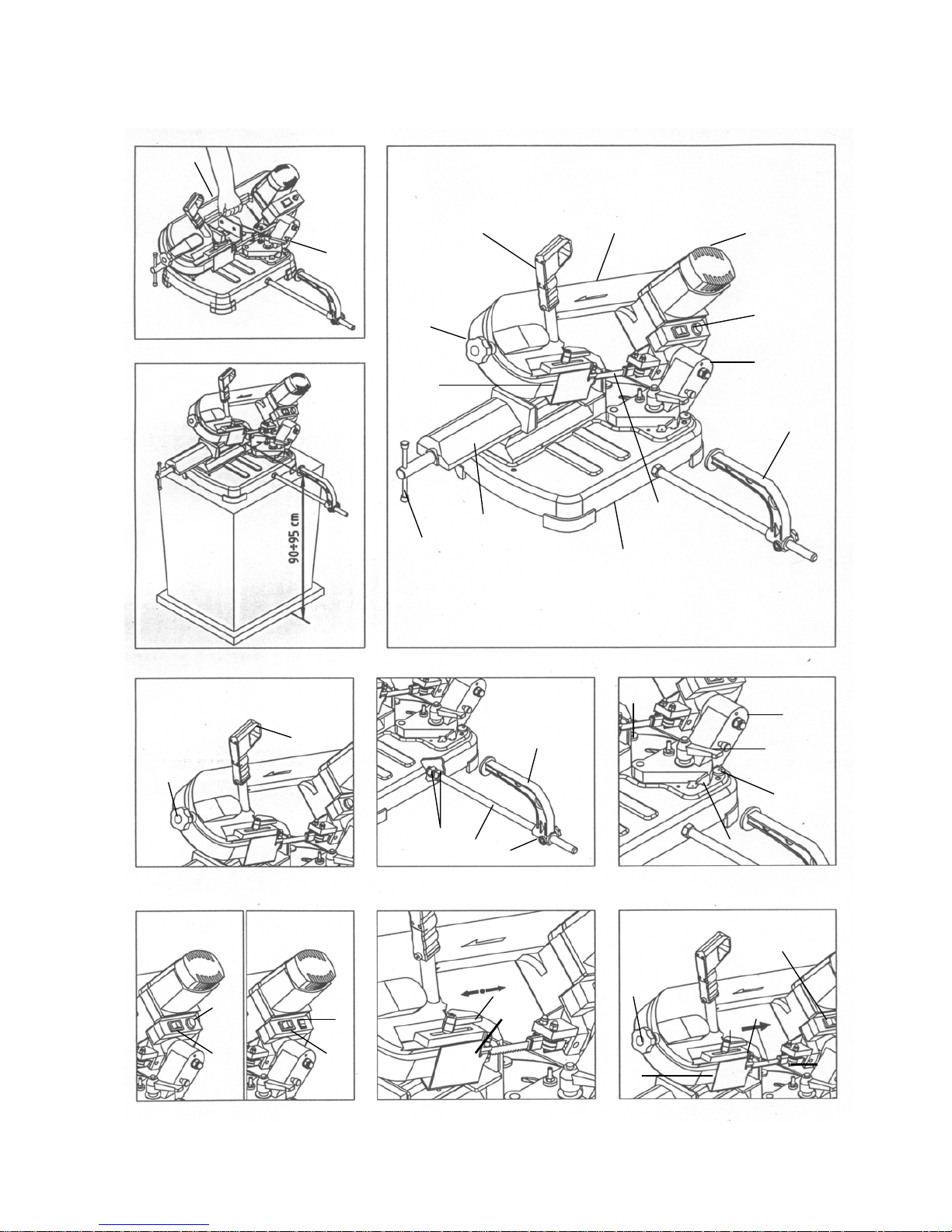
1.8 DESCRIPTION OF THE MACHINE (Fig.1)
The belt sawing machine consists of two basic parts: the
machine body (5) complete with motor and drive (7) which
is integrated into lower part, consisting of the clamp (11)
and the base (13), by means of the swivel support (9).
Here is a list of the main parts with the number indicating it
in the drawing.
Legend Fig. 1
1 - Command grip
2 - Blade tension handwheel
4 - Sliding blade guide
5 - Machine body
6 - Blade
7 - Motor
8 - Control box
9 - Bar stop
10 - Clamp (vice)
11 - Morsa
12 - Clamp drive
13 - Base
2.0 INSTALLAZIONE
2.1 REMOVING THE PACKING
Remove the wooden frame which protects the
machine during transit.
3

Try not to damage the frame as you may have to move
the machine long distances or store it for long
periods.
2.2 HANDLING (Fig.2)
As the machine is not heavy (Kg 16), it can be
lifted and moved by a single person by gripping it
from the machine body (5), duly clamped (see pint 2.3)
2.3 TRANSPORT (Fig.2)
It is necessary to low the saw body till the lower position
and fix it to the base : it is sufficient to insert the pin U in
the hole in the body , then lift the machine, gripping it as
showed in Fig.2.
For transport the machine, it is better to place it in the box
it was when purchased.
Ensure it is placed in the correct position indicated by the
arrows on the packaging.
Pay careful attention to the ideogram printed on the box as
they provide all necessary information for palletization and
stacking of boxes.
Tying the load down with ropes or safety belts is
raccomended during transportation to prevent the load
from sliding or falling.
2.4 POSITION/WORK STATION (Fig.3)
Place the machine on a sufficiently flat workbench so that
the machine has the better possible stability.
In respect of ergonomic criteria during cutting operations,
the workbench must be positioned at such a height that
the clamp level is between 90 and 95 cm from the ground
(see fig.3)
ATTENTION: Make sure that the machine is placed in a
working area with suitable environmental conditions
and lighting. The general conditions of the working
environment are of fundamental importance for
accident prevention.
2.5 ELECTRICAL CONNECTIONS
Check that the mains to which the machine is connected is
earthed in accordance with current safety regulations and
that the power point is in good condition.
Remember that there should be a magnetothermic
protective device fitted upstream of the mains to protect all
the conductors from short circuits and overloads.
This protective device should be selected according to the
electrical features of the machine listed below:
Nominal voltage.................................1~,115 / 230V
Nominal frequency.............................50/60Hertz
Max programmed absorbed value .....3.8Ampere
Nominal input power..........................1250Watt
Power factor.......................................0.93
Nominal speed .................................14.000-19.000rpm
Insulation ...........................................Class B
Type of service...................................intermittent S4-60 %
In case of power failure in mains, while you wait for power
to be restored there is no danger hazard may arise: in face,
the electronic governor O or main switch D is also
equipped with a reset function which prevents the machine
from restarting automatically. ..............................................
The motor of your sawing machine (electronic version)is
equipped with a protective heat circuit breaker which
interrupts the power supply when the temperature of the
coils rises too high.
When the power supply is interrupted, wait for normal
reset.
3.0 ADJUSTING (Fig. 4-5-6-7-8)
3.1 TENSION OF THE BLADE (Fig.4)
Turn the handwheel B in a clockwise direction until it
locks.
If the tension is too high, the blade tends to escape
from the guide. In this case, slacken the blade tension
by turning of one/two turns the handwheel B in a anti
clockwise direction.
3.2 BAR STOP (Fig.5)
Use the bar stop supplied if you have to do several cuts on
pieces of the same length.
In this way you do not have to repeat the same
measurement each time.
Screw rod E into the hole of the base and fasten it with
nuts F. Slacken the handwheel G and place the stop L at
the correct distance from the blade. Tighten handwheel G
again.
3.3 Cutting angle (Fig.6)
The band saw can cut at an angle varying from 0 to 45
degrees : it is sufficient to slacken the handle I and turn
the swiwel support J towards the respective limit stops H
and K.
For all intermediate angles, turn the swiwel support J until
the mark M on the support matches the corresponding
position on the plate.
Then lock the rotating support J again.
3.4 CUTTING SPEED (Fig.7)
Two speed version
Depending on the type of material and its section (see
CUTTINGTABLE) you can choose two different cutting
speed 60 or 80 m/min. by means of the switch N.
Electronic version
Your sawing machine is equipped with CESC (Constant
Electronic Speed Control), which allows gradual and
continuous variation of the cutting speed , adapting it to
the type and dimension of the material to be cut (see
cutting table).
To select the most suitable speed, use the speed control
knob O to increase or decrease the speed as you require.
Example:
Stainless Steel: 30m/min. position 1
Common Steel: 40-60m/min. position 2-3-4
Allum.Alloy: 80m/min. position 6
Pipes/sections: 70-80m/min position 5-6
4
 Loading...