

Page 1
Smart Screen
Tech.com! L! C
THIS IS FRAGILE - read instructions before use and connect up with Power OFF!
Introduction
The Smart Screen simulates the display screens found in many railway stations and on board
trains, as well as other places such as motorways, buses, bus stops and sports stadiums.
You can customise and display your own messages and the module can store 10 different screens,
each with 2 lines of text, the top line with the option to include a clock and the bottom line capable
of much longer text which scrolls automatically when the sentence is wider than the screen.
12:50: Norwich 12:47
Calling at Acle, Lingwood, B
Your own messages need to be programmed into the screen using a DCC controller, but once set
up they can be powered by either DC or DCC, and each message can be controlled in a number of
ways including Track Sensors, Loco direction, DCC commands, Switches or cycling the messages.
We have tried to make it as easy to set up and use as possible, but DCC controllers were never
designed to set up message displays and because there are so many options it is best to plan your
message before starting to program. Should you make mistakes while setting up, or want to change
messages later, you can edit messages or completely clear the whole screen and start again.
Function keys are used to enter most text and control options, so if you have a choice of DCC
controllers available to you, if possible choose one with 10 individual function keys F0 to F9 which
are easy to use by a single press, rather than multiple button shifts to enter each function.
This booklet contains 5 projects which will help you understand what the Smart Screen can do.
12:50: Norwich 12:48
roaching *** Train now app
Getting Started
The Smart Screen is very fragile and should always be handled with care. The screen itself is
made of thin glass and so care must be taken not to put it under any stress, especially making sure
you rest the screen face down on a completely flat and clean surface when soldering terminals - a
piece of expanded polystyrene from packaging can make a good base on which to work.
The first thing you need to do is wire it up for which you will need a 15-25 watt fine tipped soldering
iron and solder, together with some wire cutters and strippers. A length of fine PTFE insulated wire
is included and is easy to conceal into your own models or one of the optional screen enclosures.
Prepare a completely clean, flat soft surface to work on and start by carefully removing the screen
from this booklet by gently peeling the paper away from the back of the screen, not the other way
round - we suggest the protective screen film is left on until you are ready to fit it on your layout.
Getting connected
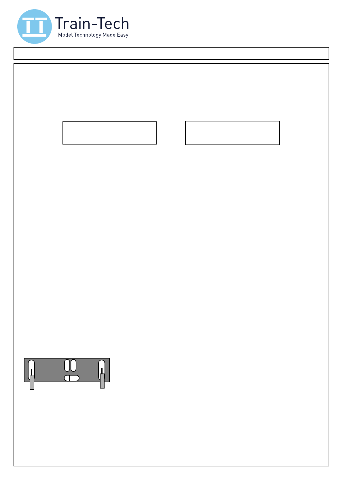
Turning the screen glass side down onto a flat clean surface you will see the following connections:
!!!!! P & P are the Power input solder ‘pads’
! A B
P!! ! P
!!!!! A & B are control input solder ‘pads’ for Track Sensors or switches
© Train
!!!!! C is the common input solder ‘pad’
!!!!! L is Address reset ‘pad’ - do not solder!
Connect to 9-16v dc or DCC
!!!!! !
Start by soldering wires flush onto the P power solder pads - solder quickly in 1-2 seconds max
and do not apply too much solder to ensure it remains slim, especially if mounting in an enclosure.
Turn the screen over and when you are ready to set the screen up connect the two power wires to
the DCC controller regular track output and turn on when you should see the demo come on the
screen (or if you just want to see the demo you can connect a 9V battery or 9-16 volt smooth dc).
A demo is preloaded into each new screen but deletes itself as soon as you program it.
You are now ready to plan and setup the Smart Screen with your messages - see following pages.
1
Page 2
Programming the Smart Screen
•
Whilst there are on-screen prompts to help, we strongly recommend you read through all of these
instructions as it will help you understand all the screen can do & how to set it up for your project.
We advise you to plan what you want your screen to do and show before you start programming!
You can enter your own messages and decide how they will be controlled and these must be set
up using a DCC controller, however once programmed it can be powered by either DCC or DC.
We show how to enter messages, how to control them and how to change setup addresses.
Once messages have been programmed screens can be controlled in a number of different ways:
• Loco direction - fit on side of a DMU or coach to show destinations which change with direction
Control screen message by Track Sensor, Sensor Signal, Switch, button, reed switch, logic level
•
• DCC Accessory - eg Station could show different destinations depending on where a point is set
Manually control which one of 10 screens is shown using a DCC controller
•
Automatically cycle between screens at a time interval you set (1 to 60 second intervals)
•
Each Smart Screen is given two loco addresses, one used for programming the messages and
the other to set the clock - these addresses may be changed but they should never be the same
address as any loco etc you already run or you will randomly program or corrupt the screen!
• Programming mode Before starting, reset DCC controller by turning it off - wait - then on
•!First connect the smart screen to the standard DCC Track output of your DCC controller - note
do not connect it to the programming track output! See page 1 for connection details.
•"Set your controller to Programming address (factory default is Loco address 55), then press F8.
NB If you do not know programming address you can reset it by briefly touching together the rear
contacts L & C ; note this resets both program & clock address to their default addresses.
1 Message entry and editing
From the programming screen press F4 (Function 4) to Edit a Message:
F4 Edit message
F5 Edit controls
Select the message letter you want to set up (A to J) using F4 and F5, then press F6 to create or
edit your message for that screen. Note that if you want to include a real time clock on your Smart
Screen (press F0 / ) it is best to do this before entering text so that you see how much space
you have to enter text on the top line. The bottom line can store up to 137 characters.
Top line here 12.35
If bottom line is longer than the screen it automatically scrolls…..
Use the keys below to create your message - a _ cursor shows you where you are on the screen
F1 Move cursor >
F2 Move cursor < (Note F12 does same as F2 because on some controllers F2 is momentary)
F3 / F4 Choose character
F5 Upper or lower case
F6 Insert a character
F7 Delete a character
F8 Save message and finish
F9 Erase this message (then select F8 to save the clear message)
F0 or F10 Insert / Remove Clock (note F0 button is marked Lamp on some controllers)
Once you have filled the top line it will automatically move to the lower line - if you do not want any
character in a location just insert a space. When your second line text is longer than the screen
width, the screen will automatically scroll the second line continuously to display all the text.
Edit Message: B
F4 - F5 + F6 Edit
When you have finished press F8 to save this message or Press F9 to erase the whole message.
To clear all messages from the Smart screen and start again use the Full reset - see page 3
Tip If you get to something you do not wish to change, Press F8 or turn off power for 5 seconds
2
Page 3
2!Set how the messages should be controlled
From the programming screen press F5 Edit Controls, then choose from the following:
F4 Loco F5 Accessory
F6 Cycle F7 Settings
F4 Loco Sets the screen to control messages from a Loco address of your choice.
Enter the Loco address as a 4 digit number - include the zeros if the address is less than 4 digits.
Use F4 to choose the first digit, F5 to move to the next digit and F6 to save the address.
F4+ F5 Next F6 Save
!!!! This example shows messages will be controlled by Loco address 8
Loco address : 0008
!!!! Never use the same address as the Program or Clock address!
• If messages only in screens A&B they are controlled by Loco direction -ideal for on-train displays
If there are messages in screens C to J then they are controlled by the following Functions:
•
! <Direction> shows message A! <Direction> shows message B! F1 shows message C
! F2 shows message D!! F3 shows message E!! F4 shows message F
! F5 shows message G!! F6 shows message H!! F7 shows message I
! F8 shows message J
F5 Accessory Enables you to control your Screen messages from up to 5 Accessory addresses
Screen messages are allocated to Accessory addresses in pairs - one pair per address
•
Press F4 / F5 to choose the screen pair, then Press F6. Then change your controller to DCC
•
accessory mode, set your accessory address, then send < or > (1 or 2) to store that address.
F6 Cycle Cycles screens which have messages in them sequentially at a time interval you set.
F4 and F5 lets you adjust time between each change in seconds (s), then F6 saves and starts it.
•
3!Changing the Program address, Clock address, and how to do a Full Reset
F7 Settings Facility to set Clock setting address, Screen program address or a full reset and clear
F4 Clock Changes the address at which you can set the time - the default is loco address 56
F4 Clock F5 Reset
!!!!! !! !! This example shows address 76
F6 Program address
The clock forgets the time as soon as power is lost, but it can be set using a DCC controller.
This facility allows you to set the address from which you set the clock - if you have more than one
screen you can give them all the same clock setting address so they can all easily be set together.
F5 Reset Deletes all messages & resets clock setting address & program address to defaults.
• Offers either F8 Clear all messages and reset addresses! or F1 Cancel the reset
F6 Program address Enables you to change the main screen programming address (default 55)
F4 Clock F5 Reset
!!!!! !! !! This example shows address 150
F6 Program address
Note down any new address you program or you will need to reset to default by shorting rear contacts L & C: page 1
F4+ F5 Next F6 Save
Clock address : 0076
F4+ F5 Next F6 Save
Program address: 0150
4!Setting the clock time
The clock is set using a different loco address from the main screen - the default address is 56.
Clock setting has a separate address so that you can have multiple Smart Screens on a layout
whose main messages and controls can be set individually, but the clocks can all be set at the
same time because they can share the same address. See above to change set clock address.
1 To set the time, first set your DCC controller to the loco address of the set clock (default 56).
2 To set the time use the Function keys to enter the time as a 4 digit number (24hr clock format).
Eg to set the time to 08:52 press Function keys F0 F8 F5 F2 note you must enter 4 digits
Important: Note that the F0 button is marked as a Lamp on some controllers
• To make time display the same on every power up, enter time as above then press F5 F5 F5 F5
• The clock keeps reasonable accuracy over a day, but if on continuously will need to be corrected
3
Page 4
Project 1: Destination screen on a train which changes with direction
Tech.com! L! C
•
You can fit a smart screen(s) in or above the side window of a modern coach or multiple unit to
show the destination of the train and which change with direction automatically. It can run on DCC
layouts (giving screen the same loco address as the train decoder), or on DC layouts where it will
detect the polarity on the track (though note on DC the screen will go off as the train slows-stops).
•"Entering the screen messages See pages 2 & 3 for screen programming and message entry
Usually the top line shows the final destination and the bottom line shows stations leading to the
final destination - a clock is not usually seen on an on-train display.
Note you should only program text into screen messages A and B for this project - if not other
screens may be shown when Function keys are used to control sounds etc. You can most easily
clear messages on unwanted screens completely using the ‘Erase this message’ command (F9),
or to clear all messages from the screen select F5 Display Control, F7 Settings then F5 Reset.
So after programming Screen A could be something like this:
London Liverpool St
Calling at Manningtree, Colchester, Chelmsford, Stratford...
Note that second line of text will often be
longer than screen but this will
automatically scroll when screen is active.
And Screen B could show the other destination with stations leading to it in reverse:
Ipswich
Calling at Stratford, Chelmsford, Colchester, Manningtree...
Note that second line of text will often be
longer than screen but this will
automatically scroll when screen is active.
•"Setting up a Destination screen on a Digital DCC fitted train
After entering the messages for both screens you now need to tell the Smart Screen how to
control them. On DCC you need to tell the smart screen the loco address of your train as follows:
F4 Edit message
F5 Edit controls
F4 Loco F5 Accessory
F6 Cycle F7 Settings
F4+ F5 Next F6 Save
Loco address : 0008
Enter the Loco address as a 4 digit number - include the zeros if the address is less than 4 digits.
Use F4 to choose the first digit, F5 to move to the next digit and F6 to save the address.
On DCC if train destinations run in wrong directions reverse loco direction CV in the loco decoder
• Setting up a Destination screen on an Analogue DC train
If you are using this on a DC controlled train you just need to wire the Power solder pads P P to
the wheel pickups - the Smart Screen will detect it is connected to DC and display Message A or B
depending on the applied polarity, though note the screen will go off as the train slows and stops.
On DC If the train destinations run in wrong direction, reverse connections to the wheel pickups.
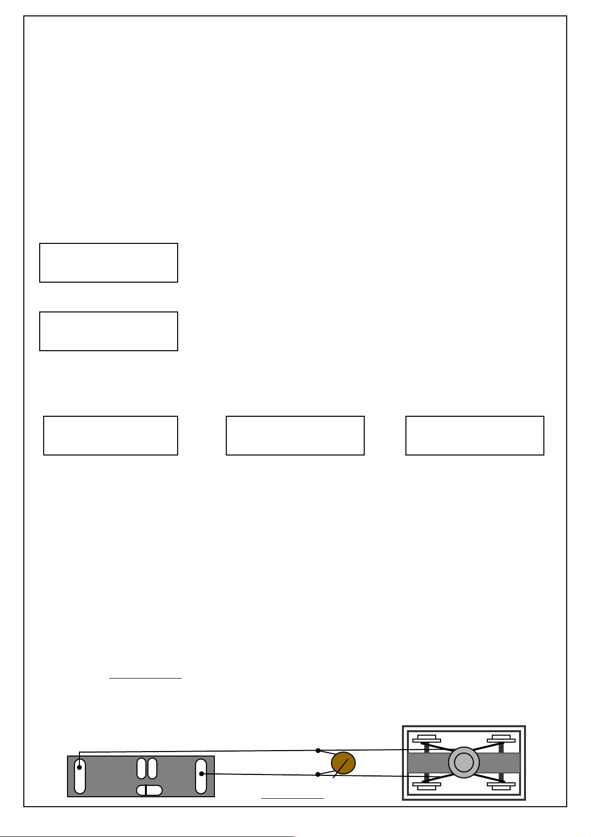
Connecting the Smart Screen
•
Wiring is the same on either DC or DCC, needing only connection to the track power via pick ups
in a multiple unit or coach with lights etc - use thin flexible wire so as not to impede smooth motion
of the bogie. As with all things model railways, clean track and wheels will help provide a stable
display, but a non-polarised capacitor of a few microfarad in parallel with the pickup wires will help
provide backup power for a small amount of time when it loses power momentarily on points etc.
Smart Screen can be mounted behind
a window using tape or blue tak etc
! A B
P!! ! P
© Train
To help prevent screen flicker fit
a 25V non-polarised capacitor
Bogie with pickups for lights or motor
4
Page 5
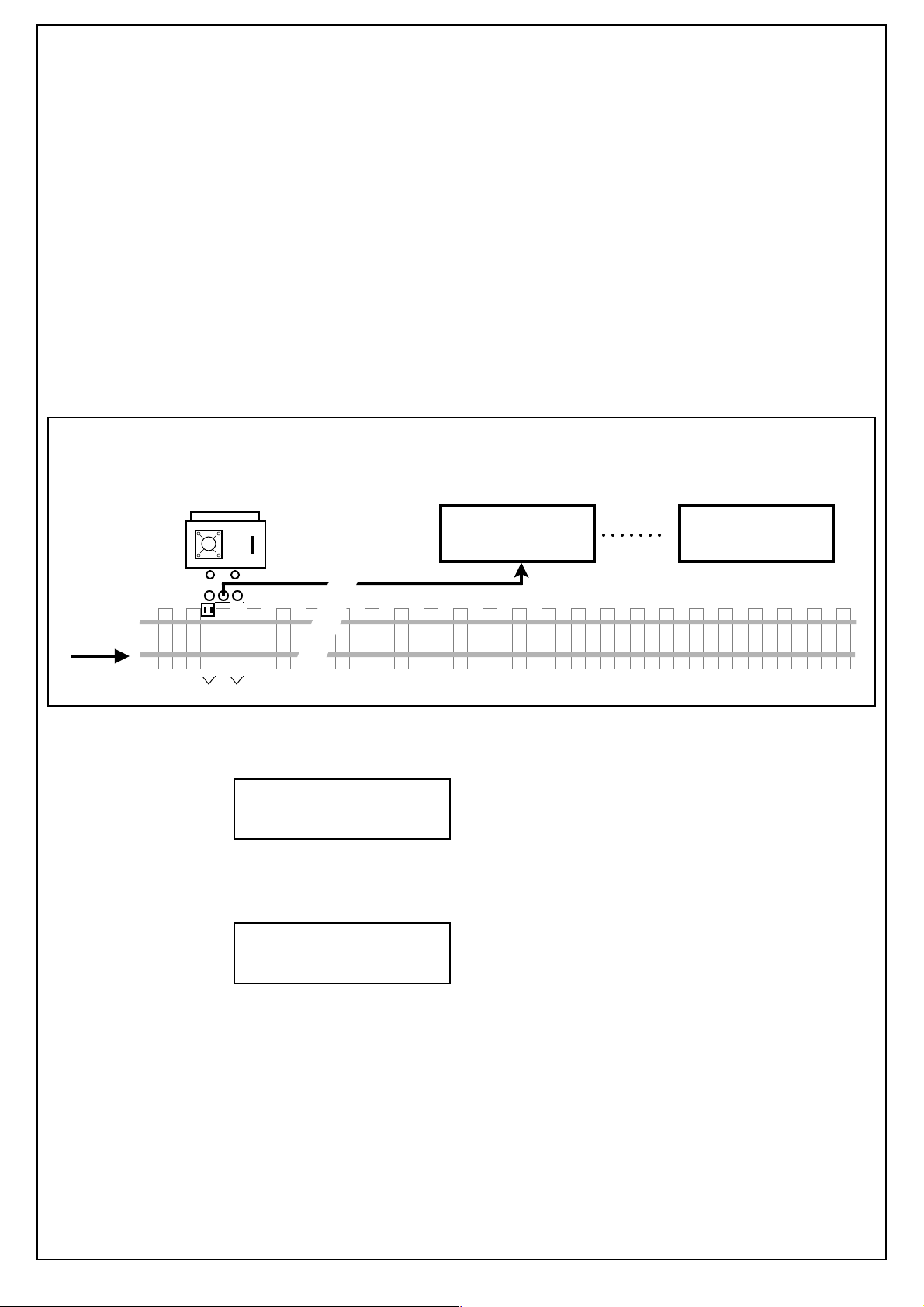
Project 2: Platform display messages controlled by Trains passing sensors
•
You can fit a Smart Screen onto a station platform to show appropriate messages as trains arrive
or depart which are controlled automatically by trains passing Track Sensors (note that Train-Tech
Sensor Signals can be used as Track Sensors in exactly the same way).
One or two Track Sensors may be connected to a Smart Screen - each can trigger two messages:
Track Sensor connected to Smart Screen input A displays message B as the train goes over it
•
and then displays message A after the train has passed.
•"Track Sensor connected to Smart Screen input B displays message D as the train goes over it
and then displays message C after the train has passed.
Planning !!
Plan where to locate your Track Sensor(s) and the messages you want to display for each one.
The example below shows a Track Sensor connected to input A of a Smart Screen on the
approach to a station and as the train goes over the sensor it triggers screen message A which
shows destination, time and a ‘stand back clear of platform’ warning:
Track sensor
on approach to station
ooooooo
Single wire link from Sensor to Screen input A
Direction
of Trains
Your Smart Screen must be powered from the same DC or DCC supply as the Track Sensor
Smart Screen mounted on the platform
Screen Message B:
As train goes over sensor
07:20 Norwich 07:17
**Stand back-Train ap
Screen Message A:
After train has past sensor
07:20 Norwich 07:18
Calling at Acle, Lingwo
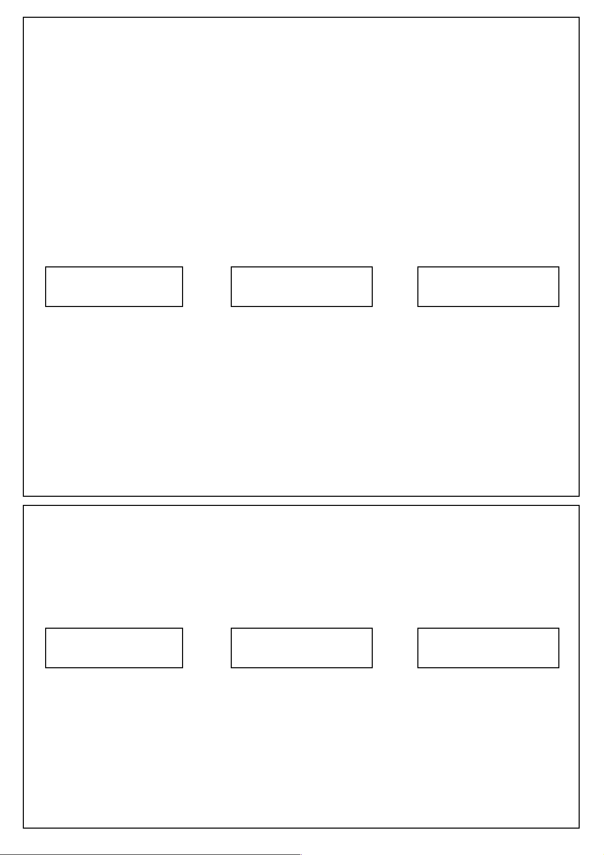
The following shows the text you would program for each screen used in this example. We have
also turned on the Clock. See pages 2 and 3 for programming, message entry and clock
Screen message B:
07.20 Norwich 07:17
** Stand back - Train approaching**
Note that bottom line of longer
text will automatically scroll.
Once the train has passed the Track sensor and it is in the station Screen message A will show
the destination and time on the top line and the lower line shows where the train is calling at.
Screen message A:
07.20 Norwich 07:18
Calling at Acle, Lingwood, Brundall
Note that bottom line of longer
text will automatically scroll.
Further ideas
If your station has a second track on the other side of the platform you can fit another Track
Sensor on that approach and connect it to Smart Screen input B to trigger similar messages for
the other track. Or alternatively fit a second track sensor just after the station so that it displays a
“Train Departing” message. The screen displayed is the most recent Track Sensor trigger.
You can also set the Smart Screen to cycle general messages in the background until a train goes
past a Track Sensor - for example “Do not leave baggage unattended”. The Cycle messages
control will play all messages in sequence at a time interval you set, though Track Sensors have
priority to interrupt and play their messages as Trains go past Track Sensors.
See page 3 to see how to set up the Cycle message control option.
5
Page 6
• Project 3: Platform Screen messages change with DCC controlled Points
DCC Accessory commands are most commonly used to operate points or signals, or to switch
accessories on and off. Accessory commands are completely different to Loco commands in that
an accessory address only has two possible conditions or states, on or off (or left or right).
Smart Screen can be set up to be controlled by DCC accessory commands, with a pair of screen
messages being assigned to one accessory address, one screen for each possible state.
So for example, you could program Smart Screen to display Screen Message A or B depending
on the state of Accessory address 1 which you set from your controller.
You can also give Smart Screens the same address as another accessory on your layout so that
they respond together. For example, if you have a DCC controlled Point at the end of a station
platform which routes a train to one of two destinations, you can program a pair of screen
messages to operate on the same address as the point so that the screen shows a different
destination depending on the position of the point.
To set Smart Screen to be controlled by DCC accessory commands use the following settings:
F4 Edit message
F5 Edit controls
F4- and F5+ lets you to choose which message pair (AB, CD, EF, GH or IJ) you want to assign.
When you have chosen the message pair, press F6 which will take you to a screen asking you to
send an accessory command at the address you want your message pair to respond to.
Set your controller to Accessory command mode*, set up the accessory address you want to
assign to this message pair and send a < or > direction control to the screen (on some controllers
1 or 2 replaces < or >. After it receives the accessory command it says Saving Address.
Once set to be controlled by DCC accessory commands, Smart Screen can display up to 5 pairs
of messages, each pair assigned to a different DCC accessory address of your choice.
The Screen always displays the message for the most recent command received.
*Note that to control an accessory you usually have to set the controller to accessory command
mode - details of how to do this will be given in your controller’s instructions.
F4 Loco F5 Accessory
F6 Cycle F7 Settings
Control message: AB
F4 - F5+ F6 Edit
• Project 4: Screen messages controlled manually by a DCC controller
You can manually control your Smart Screen messages using your DCC controller.
This is done by assigning an otherwise unused Loco address to the Smart Screen and using the
Direction and Function keys on your controller set to that loco address to control them.
Make sure you do not use the same address for loco control as the program or clock address!
To set up the screen so that messages are controlled by your controller use the following menus:
F4 Edit message
F5 Edit controls
Enter the Loco address as a 4 digit number - include zeros if the address is less than 4 digits.
Use F4 to choose first digit, F5 to move to the next digit and F6 to save it.
You can now control which message is displayed on the Smart Screen by setting your controller to
your chosen loco address and using the Direction and Function keys to display screen messages:
!!< > Direction shows message A!! < > Direction shows message B
!!F1 shows message C !! ! F2 shows message D
!!F3 shows message E!! ! F4 shows message F
!!F5 shows message G!! ! F6 shows message H
!!F7 shows message I!! ! F8 shows message J
F4 Loco F5 Accessory
F6 Cycle F7 Settings
6
F4+ F5 Next F6 Save
Loco address : 0008
Page 7
• Project 5: Controlling message screens by switches or external devices
Tech.com! L! C
Tech.com! L! C
Tech.com! L! C
In addition to controlling screen messages by Track Sensors, Train direction, DCC points etc, you
can also control them using conventional switches such as push buttons, toggle switches or reed
switches (which are activated by magnets) connected to the inputs.
Always turn all power off before connecting wires and soldering!
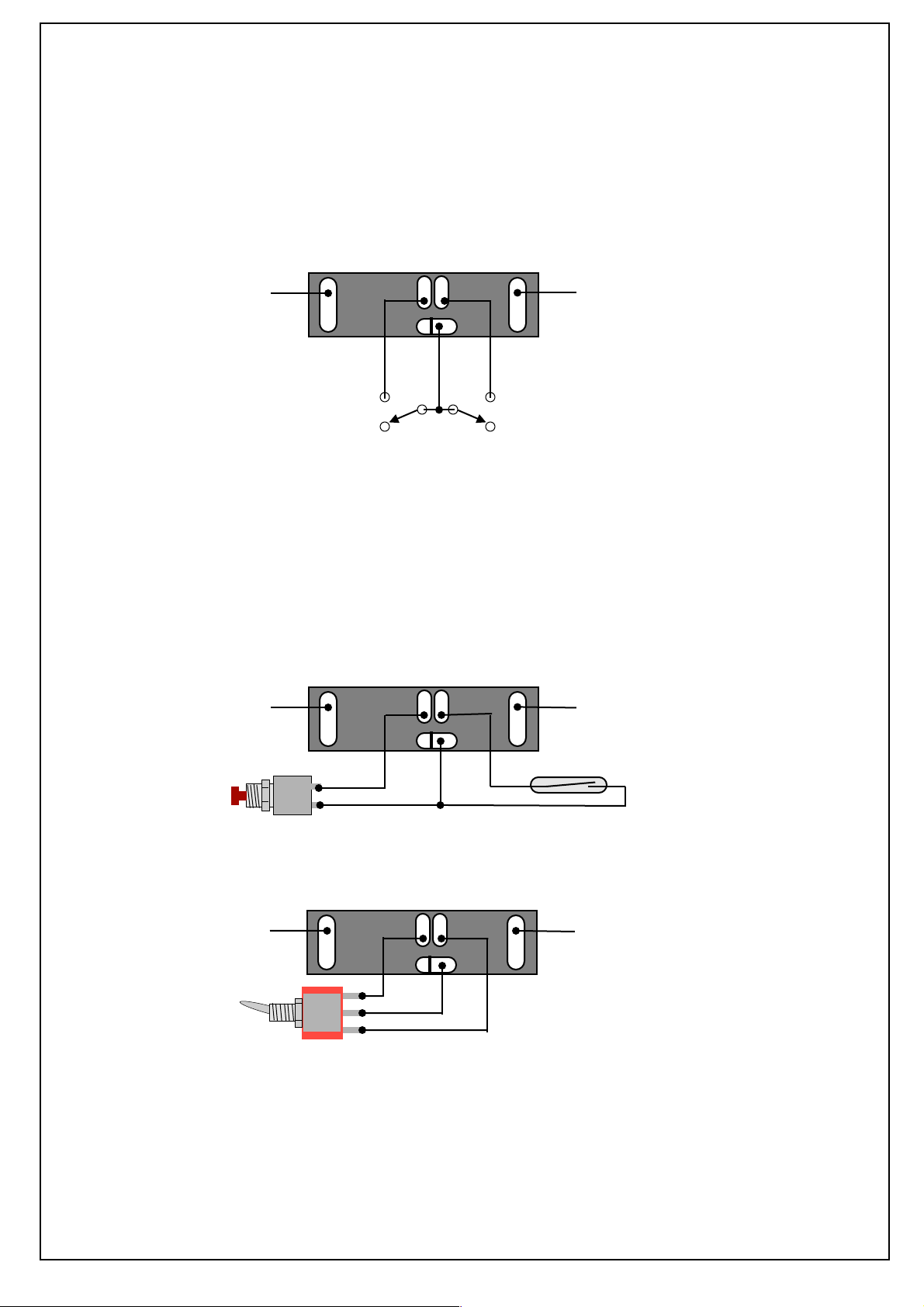
There are two solder pad inputs on the back of the Smart Screen marked A and B and the
common solder pad is marked C and the inputs are activated by connecting the inputs A or B to
the common C. You can connect to and use either or both inputs, but be careful when soldering a
wire to the C pad as it is close to the L reset pad - take care not to accidentally bridge C and L!
Power
! A B
P!! ! P
© Train
Input A
Switch A
Power
common
Input B
Switch B
Input functions
• If only one or two messages are stored in the memory:
Activating input A displays message screen A; Activating input B displays message screen B
If more than two messages are stored (ie anything in message screens C to J):
•
Activating input A or B cycles round the messages, one screen at a time for each activation
The following shows a selection of different devices which can be connected.
Example 1: Push button connected to input A and reed switch connected to input B
A Reed switch is a small
glass tube containing 2 fine
contact wires very close
together but not touching.
When a magnet gets close
the contacts touch and
makes the circuit. Can be
used for detecting trains etc
Push button
Power Power
! A B
P!! ! P
© Train
Reed Switch
Example 2: Single pole Toggle switch wired to inputs A and B to switch between A and B
If you fit switches quite a
Power Power
Toggle switch which
selects between
input A or input B
! A B
P!! ! P
© Train
long way from the Smart
Screen the wires may be
prone to pick up interference
such as motor noise etc.
To suppress this fit a small
100nF capacitor in parallel
with the switch connections
Example 3: Controlling Smart Screen from a system ! Tec hnical knowl edge r equire d
Smart Screens may be connected to other train control or hobby computer systems such as
Arduino using these inputs, though this is a specialist use for which we cannot provide technical
support, so please do not attempt this unless you understand electronics. The internal circuitry of
the smart screen operates on just 3 volts, so we strongly recommend you link the Smart Screen to
your system via a suitable low voltage opto-isolator to protect both sides. There is a pullup resistor
on both Inputs A & B so an open collector output opto-isolator will also achieve level shifting.
7
 Loading...