

Page 1
COMPREHENSIVE CATALOGUE FREE ON REQUEST
Tools etc
Train Tech overview - ask for free catalogue
Signal kits - OO/HO low cost easy to make signals for DC
Sensor Signals - easy automatic block signalling - DCC or DC
Smart Lights - small effects built in - DC/DCC - just 2 wires:
Arc welding • Emergency vehicle • TV • Fire effect •!Party disco
Automatic Coach Lights - motion - no pickups or wiring:
Older Warm White • Modern Cool White • Tail Light • Spark Arc
Automatic Tail Lights - motion - easy, no wires - lantern LED:
Flickering flame oil lamp • Modern Flashing • Constant light
Track Tester - quickly tests DC polarity or DCC - N-TT-HO-OO
SFX+ Sound capsules - no wires! - real trains - DC or DCC
Steam •!Diesel • DMU • Passenger coach • Shunted stock
Buffer Light - clip in lights for buffer stops - N or OO - DC/DCC
LFX Lighting effects - DC/DCC - screw terminals - with LEDs:
Home & Shop lighting • Welding •!Flashing Effects •!Fire
Traffic Lights - fully assembled - just connect to DC or DCC
Level Crossings - assembled - N & OO versions - DC / DCC
DCC fitted signals - slide in the track - easy one touch setup:
2 aspect • 3 aspect • 4 aspect • Dual head • Feathers • Theatre
Smart Screen animated sign - for Trains, Stations etc
DCC Signal & Point Controllers
LEDs
www.train-tech.com
SC100 - Auto Controller
©DCP Microdevelopments Limited 2018 V1.0 151118
DCP Microdevelopments, Bryon Court, Bow Street, Great Ellingham, NR17 1JB, UK
Telephone 01953 457800 • email sales@dcpmicro.com • www.dcpexpress.com
See our website, your local model shop or contact us for a free colour brochure
www.Train-Tech.com
•
Works with DCC or 12-16v smooth DC
Slides into OO track slots on DCC
Or 2 power wires for DCC or DC
Control 2, 3 or 4 aspect colour signals
Links to others for block signalling
Built in sensor to detect train
SC100 Automatic Signal Controller
Enables standard LED colour light
signals to change automatically
•
•
•
•
•
Page 2
SC100 Auto Signal Controller
Please read carefully and always connect up with the power switched OFF!
Connecting LED colour light signals to the signal controller
The SC100 has a built-in train sensor and can directly control LED colour light signals automatically.
Although originally designed for OO gauge it can also be used on N, TT and HO gauge layouts.
It is part of the Train-Tech Sensor Signal system and can interconnect with Sensor Signals, but instead of a
built-in signal you can wire to almost any type of LED colour light signal or signal heads on gantries etc.
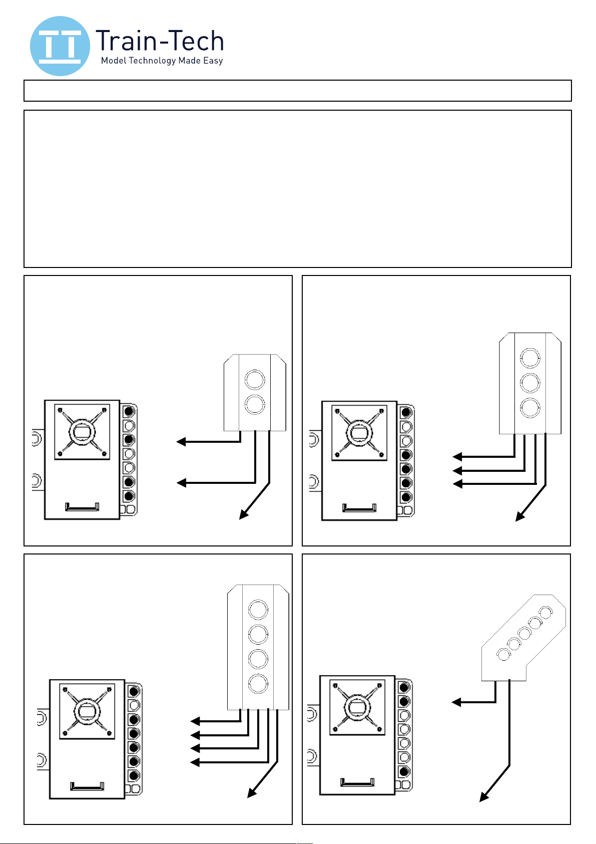
The drawings below show the wiring for each type of signal and this requires careful soldering using fine
wires to the connection pads (optionally you can fit CON8 SIL sockets - contact Train-Tech for details).
Signals have a common - negative (eg Train-Tech signal kits) or common + positive but the SC100 detects
the polarity as it is switched on and also senses whether there are 2, 3 or 4 aspect LEDs connected.
Note that resistors are built in so you do not need to use additional resistors in series with your LEDs signals.
2 aspect Red-Green Signal
G
R
Common +
Green
Red
Common -
Connect to Common - or + depending on signal
4 aspect Red-Yellow-Green-Yellow
Y
G
3 aspect Red-Yellow-Green Signal
G
Y
Common +
Green
Yello w
Red
Common -
Connect to Common - or + depending on signal
R
Connecting a Feather or Theatre
Signals can also have a Feather or Theatre
route indicator and this can be controlled
by the SC100 using DCC - see
page 6 for details.
Y
R
Common +
Yello w 2
Green
Yello w 1
Red
Common -
Connect to Common - or + depending on signal
Common +
Route
Common -
Use the same - or + common as the main signal
1"
Page 3
•!Locating the SC100 & signal " " Switch off power first!
Choose an appropriate location for your SC100 and signal. The SC100 and signal is usually
located at the same position on the track because the signal should change just after the train has
passed it, ideally not on a sharp bend because the optical sensor needs to ‘see’ the train above it.
Then you are ready to connect power to the SC100:
• Sliding SC100 into OO track suitable for DCC layouts only
DCC layouts have power on the tracks all of the time and so the SC100 and Sensor Signals can
take their power straight from the track by sliding contact fingers into the slots which some track
has for power clips. Note this is only suitable for some OO track such as Hornby and Bachmann
fixed track and a very good connection must be made at all times for reliable operation. Some
Peco track also has slots but they are wider and will need a little packing to make a solid reliable
connection. If in any doubt we recommend wiring power directly to the SC100 - see below.
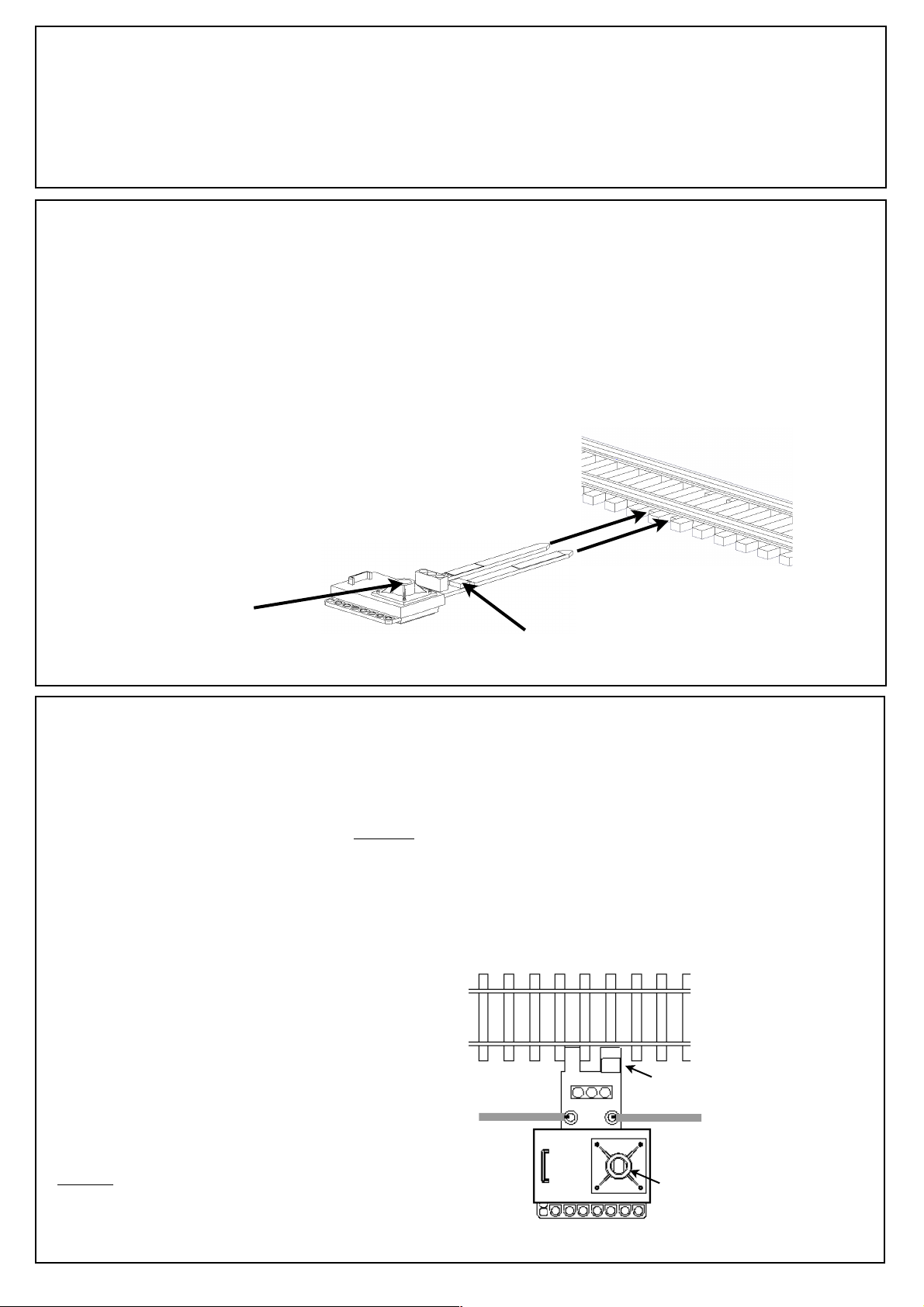
To fit SC100 into the track, find the power
clip slots in the track between the rails and
the sleepers and, holding the base,
carefully align and slide the contact fingers
into the slots all the way until they stop the sensor should be close to but not
touching the rail!
This may be a tight fit so take great care!
Power indicator LED
Lights red to indicate the SC100 is
powered. Light hole may be blocked
off with blue tack or similar if desired.
Sensor - careful never to let the sensor pins
to touch the rail or SC100 will be damaged!
Power clip slots
provided at regular
intervals on some track types
• Wiring the SC100 suitable for both DC and DCC layouts
If your layout is conventional DC or you have DCC but do not like the slide in fingers or do not
have suitable OO gauge track with power clip slots as above, you can wire your SC100 to the
layout power by cutting off the track fingers and soldering two wires - see below.
Signals can be powered by DCC or smooth DC and require a voltage of 12-16 Volts max and
current of approx 0.05A each (they should not be powered by an AC or unsmoothed DC supply).
Recommended supply for DC use is Gaugemaster Model GMC-WM4 12 V 1.25A Power Supply
Using a sharp pair of wire side cutters or modelling
cutters, carefully trim off the fingers exactly along the
dotted lines marked - - - - - - on the signal circuit
base, taking great care not to touch or damage the
small black sensor or any of its wires as this will
cause permanent damage!
Carefully solder 2 thin pretinned wires into the holes
marked P P on the drawing, making sure that any
loose strands or whiskers of wire do not touch
any other contacts or component!
On DC layouts connect these wires to a 12-16V
smooth DC supply, on DCC layouts connect them to
the nearest rails, DCC Bus bar or direct to the DCC
controller output.
Locating SC100 with N, TT or OO/HO track
Locate SC100 with the
sensor close to but
not actually touching
the rail. If using with N
or TT gauge track you
may need to cut away
some of the sleeper.
(This picture shows it
with N gauge track)
Power
Signal Connections
P P
Sensor
Power
Power indicator LED
2
Page 4

• Using a SC100 signal on its own
Train detect LED
As soon as the power is switched on the signal connected to the SC100 should light green. If it
does not light at all check the power connections thoroughly - see previous page.
To test push a wagon or coach past the SC100. The sensor should detect it and the signal should
change from green to red.
Several seconds after the train has passed the signal it will change back to green (via yellow if it is
a home-distant type signal). Note that the signal will only change back to green after it has not
seen any train over it for several seconds, so if you have a long train it will stay at danger for as
long as a train is moving over it. A signal used on its own can only ever work in this way because it
does not know how far ahead the train is, but if multiple SC100 and Sensor Signals are linked
together the first signal will stay at danger until a train has cleared the following block and so on
through the block sections protected by other sensor signals - see page 4.
The sensor uses infrared and is quite tolerant
of varied lighting conditions, but for reliable
operation avoid strong lights (such as the sun,
bright or flickering lights) or shadows directly
onto the sensor.
The sensor should detect most locomotives
and rolling stock, but if a particularly tall or
dark train passes undetected a small label or
dab of white paint underneath will help reflect
the infrared more consistently.
Train
Sensor
Avoid bright light or the sun
shining directly at sensor
• Manual override of a single SC100 Signal
Although SC100 / Sensor Signals will work completely autonomously, you can manually override
them to force a signal to stop/caution using either a Mimic Switch or a DCC command. On the real
railway these are called semi-automatic signals & exist so that a central signal box can stop trains
in the event of an emergency, like a tree which has fallen on the line or other operational reasons.
A Mimic Switch is an easy way to override a SC100 Signal and also offers other benefits such as
an LED showing the colour of the signal and another LED which lights when the train passes the
signal, as well as controlling a route indicator etc. Wiring is simple too with just one wire from the
signal to the mimic switch and it works on both DC and DCC layouts. (details on a following page)
This picture shows a
Sensor Signal, but the
same principles apply
to SC100 signals
Signal colour LED
Mimic
Switch
A Mimic switch
connects to a
Sensor Signal using
just one wire and
allows manual
override of the
signal as well as
LEDs which show
signal state and
train detection, etc
DCC override
If you are using the SC100 Signal on a DCC layout you can override the signal to stop/caution
using a single command to an address you set up using One-Touch DCC - see page 5. (Make
sure that you choose an address not used on anything else on your layout!)
3
Page 5

• Using multiple SC100 and Sensor Signals
Sensor Signals and SC100 really come into their own when you link several together because
they all sequence as a complete block section system automatically! Mixed 2, 3 and 4 aspect
SC100 and Sensor Signals will all work together, including distant only signals which show yellow
when the next signal is red. The example below shows 4 x 4 aspect signals linked, although in
practice you can run virtually any number of signals connected in this way as long as you have
sufficient power to supply them all (each signal needs approximately 0.05A).
Wiring is easy because you just need one
Use solid core
wire to link signals
Train
Sensor
Link first signal to the last on complete circuits for automatic operation
This picture shows
Sensor Signals, but the
same principles apply
to SC100 signals
If the SC100 / Sensor signals are located in a
continuous circuit of track then you can link every
signal to each other front to back in a loop for fully automatic
block signalling around the track.
Tip - careful not to obstruct the sensor ‘view’ with the link wires
wire between each signal, the output of one
to the input of the next one as shown.
Always use Single core wire (1/0.6mm
type is best) stripped 3-4mm at each end
which just plugs into the signal sockets you can either hide wires under your
baseboard or run them on the top alongside
the track - just like the real thing!
If you are using SC100/Sensor Signals on a
complete circuit, you can link every signal to
each other to make each section automatic.
If it is an ‘end to end’ type layout the last
signal will turn green a short while after the
end of the train has passed the signal.
If the signals are used on a single line which
has trains running in both directions you can
signal both sides, but only link together
signals running in the same direction.
If a train runs backwards the signals will
turn red (or yellow on a distant signal), then
after a short time cycle back to green.
• Manual override of multiple SC100 and Sensor Signals
Multiple Sensor Signal and SC100 Signals can be overridden to show stop / caution in the same
way as a single signal can, and because they are linked they also control any distant signals
located in front of them to correctly display yellow or double yellow etc.
This picture shows
Sensor Signals, but the
same principles apply
to SC100 signals
Signal colour LED
Mimic switches can be wired to one
or more linked SC100 / Sensor
Signals using just a single wire.
The top LED lights the same colour
as the signal. The bottom LED
flashes as a train goes past a signal
and lights continuously while a train
is still in the following section to show
block occupancy - ideal for a control
panel to show where trains are on
your layout.
If your layout is digital you can also
manually override any signal to red
using a DCC command - see page 6
Mimic Switches
Occupancy LED
4
Page 6

• Using Mimic Switches with the SC100 and Sensor Signals
•
Sensor signals may be used on their own but Train-Tech Mimic Switches and Mimic Lights are a
great way of both controlling and monitoring your signals and trains on a control panel.
Mimic switches can override an SC100/Sensor Signal to show stop/caution or switch on a route
indicator and they come supplied with 2 plug-in LEDs to show the red, green or yellow state of the
signal they are connected to, as well as train presence and occupancy of the following block. It is
easy to mount using a single mounting hole and easy to connect having just a single wire to the
signal and 2 wires to the same DC or DCC supply that you are supplying the signals from.
Mimic Switches come in two versions fitted with either a 3 way toggle switch or push button and
there is also a Mimic Light version which has just the indicator lights and no control. Mimic switches
can also be used to control and monitor other Layout Link compatible products such as points and
level crossings - full instructions supplied with each Mimic product or see Train-Tech.com
Mimic Switch Wiring and Functions
LIGHT FUNCTIONS:
LED A mimics the signal status:
Red, Yellow or Green
Pulsing red if on Manual override
LED B Train passing & occupancy:
Pulses as train goes past signal
Constant while train is in following block
C
•
• ••
A
D
SWITCH FUNCTIONS:
1: Route indicator (if fitted on signal)
2: Automatic
3: Manual override - signal stop/caution
CONNECTIONS:
E
LED C (optional - no LED socket fitted)
Mimics signal’s route indicator
(if a feather or theatre version)
LED D (optional - no LED socket fitted)
Lights as train passes the sensor
LED E (optional - no LED socket fitted)
Mimics the 2nd yellow (if fitted on signal)
•
B
Fit long wire of LEDs to top marked socket •
DC / DCC power (same supply as signal)
To centre socket of SC100/Signal
DC / DCC power (same supply as signal)
• Using DCC to control an SC100 Signal
In addition to using a mimic switch you can use DCC to override a signal and/or control a route
indicator. Train-Tech products use a unique system called One-Touch DCC to easily set up any
DCC accessory - note you must set controller to DCC Accessory control mode, not loco mode.
Two ‘Learn’ Contacts
Briefly touch together the
two contacts at the end to
set signal DCC addresses
wiring to signal
To Setup an SC100 for DCC manual override control
To setup your signal for DCC manual override, turn the power on and use a short
link of insulated wire to briefly short together the 2 ‘Learn’ contacts (see picture)
until the signal lights flash, then send a Direction ▹ / " or a 1 / 2 (depending on
the make of your controller) on the accessory address you want to use to
manually override your SC100 Signal. The signal will stop flashing and your
Automatic signal can now be overridden at any time using the command and
address you chose - change it between override / automatic using ▹ / " or 1 / 2
command on your address. Other SC100/Sensor Signals linked to this signal will
react correctly too, so for example a distant will display yellow when the following
signal is red. Make sure you choose an address not used by anything else!
To set up DCC control of a Feather or Theatre connected to an SC100
To setup a signal Route Indicator, use a short link of insulated wire to briefly short
together the two ‘Learn’ contacts (see picture) until the signal lights flash, then
touch them again and the Route indicator should flash.
Send a Direction ▹ / " or a 1 / 2 (depending on your controller) on the
accessory address you want to use to use to turn the Route on. The Route will
stop flashing and will now light using the command and address you chose. You
can use the same address as a DCC controlled point so that it changes with the
point - note that the route indicator always lights with the same ▹ / " or 1 / 2 you
used to set up, so use the same as the point to make them work together.
5
Page 7

• Route Indicator Signals
Train-Tech Signals are available with ‘Feather’ and ‘Theatre’ type route indicators which can be
wired to the SC100 and switched on and off using DCC or a Mimic Switch as shown previously.
Route indicators advise the train driver which route or platform etc they are going and are often
dictated by point position. Feather and Theatres are also available on their own from Train-Tech.
The Train-Tech Theatre route indicator
can easily be set to display almost any
single character or symbol of your
choice. This is called a ‘dot matrix
display’ and is how many theatre & other
signs are created on the real railway.
DCC Control of a Signal Route Indicator
Feather or Theatre route indicators can either be on or off and are all controlled in the same way,
much like the main signal control. If you are controlling your points using DCC you can give the
route the same address so that it lights automatically when the point(s) are set to the selected
route. To set the route address, set your chosen accessory address on your controller and then
touch the Learn contacts together twice until the feather or theatre flashes. Then send a ▹ / "
Direction or 1 / 2 command from your controller to set the address for your route indicator to be
on. (NB: if you want the route to synchronise to a point operation, ensure the same command
used also sets the point to that route). More information on the DCC control page 5.
Note that like the real thing, the SC100 automatically turns off route indicator if signal is at Red.
Using Signal Heads and Gantries
•
Train-Tech now offer OO gauge Signal heads only (SH2-SH6) which are available in 2, 3 and 4
aspect versions and all include preassembled LED panels and fine connecting wire. LK1/RK1
Feathers and TK1 Theatres can also be fitted to these signal heads with just two soldered joints.
The signal heads are ideal for making your own signals, or they can be mounted on a gantry such
as this Dapol CO17 which shows how signal heads could replace the dummy signals from the kit.
Gantry Image ©Dapol
6
Page 8

• Automatic Signals
Like Sensor Signals, the SC100 incorporates an infrared sensor which automatically changes the
signal when a train passes to signal danger to following trains. When used on their own they
gradually change back to green a short time after the last part of the train has crossed over the
signal, but when linked to other SC100 or Sensor Signals (using just a single wire) they all work
together to provide fully automatic block working, each signal protecting the following block by
staying at danger until the train has left the block. We developed the Sensor Signal system after
recognising that most modellers run their layouts on their own most of the time and so do not have
time to be signalmen as well as train drivers! However much of the ‘real’ railways main lines use
automatic signalling and Sensor Signals work in a very similar way.
Signalling basics
The most basic signals are 2 aspect Home (red & green) and Distant (yellow & green). A Distant
signal is installed ahead of a home signal to give early warning to the driver of what the next signal
is, so if the Distant signal is green he knows the next signal is also green, but if it is showing yellow
he knows the next signal will be red. There are also 3 aspect Home-Distant signals with yellow
lights as well as the Red & Green which are called Home-Distant, and on high speed main lines
there are 4 aspect Outer-Distant signals with red, green and 2 yellow distant lights which give an
even earlier indication of the next 2 signals to the train driver. Much of the ‘real’ railways main lines
actually use automatic signalling and Sensor Signals work in a very similar way. We cannot cover
any real detail of signal planning and operation here, but there are many good books and websites
(eg www.signalbox.org) dedicated to the subject. The illustrations in this guide mainly show 4
aspect Sensor Signals, but the same principles apply to all variations of Train-Tech signals.
• Troubleshooting….
When powered one of the signal lights should always be lit and not flickering. If not and locos run correctly track check
•
signal power connections - if using signal contact fingers for connection check they are clean and tightly fitted between
the track sleeper and rail - clean if necessary or consider wiring the signal instead of using slide in fingers. The power
connections to every Sensor Signal linked together must be very good and consistent to ensure reliable operation.
If powering your Sensor Signal from DC it must be a Smooth DC supply between 12 and 16 volts DC maximum - we
•
can recommend the Gaugemaster GMC-WM4 power pack as ideal, being 12 volt Smooth & Regulated DC @1.25A.
If the signal stays on one colour, not changing as the train passes, check that signal is pushed in around the sleepers
•
and the sensor is close to the rail (but NOT touching!) so that it can ‘see’ the train moving over it and that there is no
bright light or sun shining directly onto the sensor to prevent it from working. We do not recommend mounting Sensor
Signals on curves because long stock can miss the sensor on outside curves or crash into the signal on inside curves.
• If signal stays on red (or yellow on a distant signal) check you have not sent an override command inadvertently - note
that Sensor Signals are set to a Test DCC address at the factory and this might be the same address as something else
on your layout, so if in doubt give it your own unique address even if you do not intend using DCC override - see page 6
If sensing is unreliable on some trains you can add a white label or white paint under the train to improve reflectivity,
•
but it should work with most stock. Do not get the signal wet or cover the sensor with paint or any other scenic material.
If your signal does not respond to DCC, double check that your controller is in accessory addressing mode (not regular
•
locomotive addressing) to set up & operate (this will be explained in your controllers instructions).
• If these steps fail please contact your supplier or us direct: www.train-tech.com sales@dcpmicro.com 01953 457800
Computer and advanced control systems
Some DCC controllers can be connected to a PC or tablet to enable computer control of locomotives and accessories for full details on compatibility consult your controller supplier. Some controllers have Railcom® or Railcom Plus® and
although our Sensor Signals will work with this system on if you are not using Railcom it is best to turn it off.
Signal design
Our signals are based on colour light signals in Norfolk which we photographed, CAD, tooled and make in the UK.
As well as Sensor signals we also make DCC fitted and switch controlled signals with Feathers & Theatres, plus a wide
range of easy to use signal and point controllers, lighting and sound effect products. Ask for our latest free brochure.
Caution
This product is not a toy but a precision model kit and as such contains small parts which may choke or harm a child.
Always take special care when using tools, electricity, adhesives and paints, especially if children or pets are nearby.
7
Publication reference D779643/4A ©DCP 2017 David Palmer
 Loading...