

Train-Tech SC1 User Manual

More details from Train-Tech.com or dcpexpress.com
SC1 - Signal Controller for controlling one or two 2 aspect LED signals
21
3
+
1
2
3
4
1
2
3
4
1
2
3
4
1
1
4
2
3
CAUTION - ALWAYS SWITCH OFF POWER TO YOUR LAYOUT BEFORE CONNECTING THIS CONTROLLER
This Signal Controller incorporates a DCC decoder to enable it to be wired directly to the track and be operated by any controller which is
able to control DCC accessories. Please read these instructions before connecting or fitting your controller.
CONNECTIONS
The SC1 is a Signal Controller which will
directly control most commercial or home built 2
aspect LED colour light signals using DCC.
Switch off power before connecting!
Connecting the SC1 to DCC
Connect the SC1 DCC input terminals to
nearby rails or the DCC controller output.
Connecting the signal LEDs
There are a wide range of LED Colour Light
signals available and they are usually supplied
with LEDs already preconnected. LEDs have a
+ and - polarity and only light when connected
one way. Either the + or - pin of every LED
needs to be connected together as a ʻcommonʼ
wire connection - this is often prewired by the
signal manufacturer and the instructions for the
signal should show the polarity connections.
The SC1 works with either common + or connected LEDs, just connect the common wire
to either + or - as marked under the SC1.
The example below shows common negative.
Note that you should NOT use resistors with the
LEDs as they are built these into the controller.
Common for - Negative LED wiring
Signal A
Green
Red/Yell
Signal B
Green
Red/Yell
-
+
Common for + Positive LED wiring
SETTING SIGNAL ADDRESSES
The SC1 can control one or two 2 aspect
signals and you need to choose a DCC address
for each signal. For this example we will use
address 72 for signal A and 84 for B.
• Set up your controller to control DCC
accessories
then set your controller to the DCC accessory
address you choose for Signal A (eg 72).
• To program signal A touch the ʻLearn buttonʼ
once - signal A lights should flash, then send
either the or ʻdirectionʼ command from
your controller which you want to control and
show green. The signal will stop flashing, show
green and is now programmed to the address
(eg 72).
• To program Signal B, set your controller to the
address you want to give B (eg 84), press the
Learn button twice and Signal B lights should
flash. As before send either the or
command from your controller which you want
to control green and Signal B will stop flashing,
show green and is now set to respond to the
other address (eg 84). Your signal will retain
your chosen address unless you change it,
which you can do by repeating this step.
-
+
+
(refer to controllers instructions),
Power
Light
Connect to track
or the DCC
controller output
Learn button
Mounting holes
Do not screw tightly
CONTROLLING THE SIGNALS
•
Control the signals by setting your controller to
the DCC accessory address of the signal and
sending a or ʻdirectionʼ command from
your controller to change the signal colour
(actual terms used for accessory control vary
between controllers so refer to its instructions)
In our example
Address (72) or = Signal A Red or Green
Address (84) or = Signal B Red or Green
Yellow can replace Red for Distant signals
Each signal can be controlled independently
with its own unique address or can be easily
synchronised to other DCC signals or points etc
by giving them the same address as each other.
For example you could program a two aspect
Home Signal with the same address as a two
aspect Distant signal, then the Distant will
automatically show the state of the following
Home signal.
Or you could set a signal to automatically show
Red when a point is set against a train going
towards it! Again all you need to do is set the
Signal to the same DCC accessory address as
the point controller address.
Synchronising addresses is especially easy to
do with Train-Tech One Touch DCC™ Point and
Signal controllers because all you need to do is
press the Learn buttons of all of the Signal and
Point Controllers you want to sync and then
send the address command - all will then be
linked and respond together on that address.
Tip
Remember that whichever or command
you use when you program the signal address
dictates the command which will always set the
signal to Green.
Using Train-Tech signal kits with the SC1
We offer a range of low cost Signal Kits which are
accurately modelled to British Outline OO scale and
which make ideal partners to our Signal controllers.
SK2/3 are single head & SK6/7 dual head (see over).
Wiring details to connect them to this controller are
shown below - simply wire each connection to the
numbered terminal on the SC1 - no resistors needed:
SK2/SK3
signal kit
Common -
Green
Red/Yellow
Connections for Signal A shown
Signal B connections are 3 & 4
2
Wiring
to SC1
SK7/SK8
signal kit
Right Red/Yell
Left Red/Yell
Common -
Right Green
Left Green
Using other manufacturers LED signals
Many other manufacturers LED signals are also widely
available for both British Outline and overseas, many
of which were tested with the SC1 in development.
Most Colour Light Signals based on LEDs should be
compatible, though check that you can remove or
bypass resistors if fitted because these are already
included inside the SC controller and will make LED
lights quite dim if left connected. If white LEDs are
used in signals like route indicators check that they
can be connected independently because white LEDʼs
require a higher voltage than other colours and if
prewired in series may not light or work correctly.
Note: If you wish to control a 3 or 4 aspect signal, or a
signal with a route indicator or feather, you will find the
SC2 controller is better suited.
Plug-In Digital Signals with DCC built in also available
1
Wiring
to SC1
Troubleshooting
Step 2 above is the ʻOne Touchʼ DCC stage which
programs the Signal address into the controller.
If it does not work:
Check that one of the signal LEDs is lit - if not and
•
DCC locos etc run correctly check the connections
between your DCC Controller, the Signal Controller
and between the LEDs and the controller
If a Signal LED is lit double check that your DCC
•
controller is in accessory addressing mode - note that
these are completely different to Locomotive
addresses and should be explained in your controller
instructions. If not check carefully that your controller
will control DCC accessories - most do but some of
the low cost starter controllers such as the Bachmann
E-Z command and Prodigy Express models do not.
Try fitting the signal to another section of track (or
•
use pieces of wire to temporarily connect it to
another track)
If these steps fail please contact your supplier or DCP
for advice and Technical support.
2
Note
The Signal Controller module may get slightly warm
when used for long periods which is quite normal.
Location board labels
These legends can be cut out and fitted to your signal.
We suggest you use the DCC address you have
programmed into your signal controller which will
make the signal easier to identify and operate.
1 2 3 4 5 6 7 8 9 10
11 12 1 3 14 1 5 16 1 7 18 19 20
21 22 23 24 25 26 27 28 29 30
31 32 33 34 35 36 37 38 39 40
41 42 43 44 45 46 47 48 49 50
51 52 53 54 55 56 57 58 59 60
61 62 63 64 65 66 67 68 69 70
71 72 73 74 75 76 77 78 79 80
81 82 83 84 85 86 87 88 89 90
91 92 93 94 95 96 97 98 99 100
AD CA DA ES EN GE GY MY PN NW
ABCDEFGHIJKLMNOPQRSTUVWXYZ
ABCDEFGHIJKLMNOPQRSTUVWXYZ
General information on using LEDs with models
LEDs are really useful lights which, unlike their
conventional filament bulb predecessors, are robust, low
power and if used correctly can effectively last forever.
But there are important considerations to using them.
Firstly LED stands for Light Emitting Diode and a diode
is an electronic component which only works electrically
in one direction, so always need to be fitted the correct
way round to work correctly and last. Whilst LEDʼs will
work on AC (alternating current) for a while, continuous
use on AC or reverse connection will reduce the life.
Most standard miniature LEDs which a modeller will use
must only have a maximum voltage of 2 to 3 volts
applied, so current flowing through the LED needs to be
reduced and this is usually done by a resistor in series
(in between), typically 1000 ohms for a 12 V supply.
However to make wiring easier for modellers all TrainTech LFX or Signal LED controllers already have
resistors built in so that LEDs can connect directly to the
module without the need for any resistors.
Train-Tech also offer packs of various LEDs for
modellers and these always come with instructions and
also suitable resistors for using them on a standard
Model Railway 12V DC supply.
Connecting LEDs
As explained previously LEDs have a polarity and must
be connected the correct way round to light. The most
popular LEDs come in 3mm and 5mm diameter cases
and look similar to this:
+
-
FLAT
SIDE
The best indication of polarity on this type of LED is to
find the flat side on the round base. This side usually
indicates the negative (Cathode) connection and the
other wire the positive (Anode) connection to power.
Another really small LED we supply for some Train-Tech
products looks like this:
+
-
There are many LEDs on the market and it is good to
experiment, but check manufacturers data for specific
connection information as there are no real standards.
Document Ref D779667/2
One-Touch DCC™ Digital Signals
• Signal with DCC decoder built into base
• Can just plug direct into track – no wires!
• Easy to fit and use – no CV programming!
• Can sync to other signals & points
DS1 Home: Red
R
and Green
G
DS2 Distant: Yellow Y and Green
G
DS3 Home Distant:
R
Y
G
DS4 Distant: Y
G
Y
DS5 Outer Distant:
R
Y
G
Y
DS5HS Outer Dist:
R
Y
G
Y
(High Speed mainline)
DS6 Dual Head Home:
R
G
DS7 Dual Head Distant: Y
G
DS8 Stop-Caution: Red
R
and Yellow
Y
General purpose signal kit:
SK1 Basic kit 2/3/4 aspect & dual heads - no LEDs
Signal kits with LEDs and resistors
SK2 Home 2 aspect kit with Red
R
Green
G
LEDs
SK3 Distant 2 aspect kit with Y G LEDs
SK4 Home Distant 3 aspect kit with
R
Y
G
LEDs
SK5 Distant 3 aspect kit with Y
G
Y
LEDs
SK6 Outer Distant 4 aspect with
R
Y
G Y
LEDs
SK7 Dual head Home 2 aspect with
R
G
LEDs
SK8 Dual head Distant 2 aspect with
Y
G
LEDs
Track not included
DCC
OO
HO
WIRE
FREE
DS1/2
DS6/7
One-Touch DCC™ Point Controllers
DCC
OO
HO N Z
• Control points and uncouplers using DCC
• Easy to use – No CV programming!
• Work with most solenoid point motors
• Just connect 2 wires to nearby DCC rails
• Easy screw terminals – no soldering
• Built in CDU for efficient operation
• Can sync to other points and signals
One-Touch DCC™ Point controllers
PC1 DCC Single Point Controller
PC2 DCC Quad Points Controller
Point motor and track not included
PC1
PC2
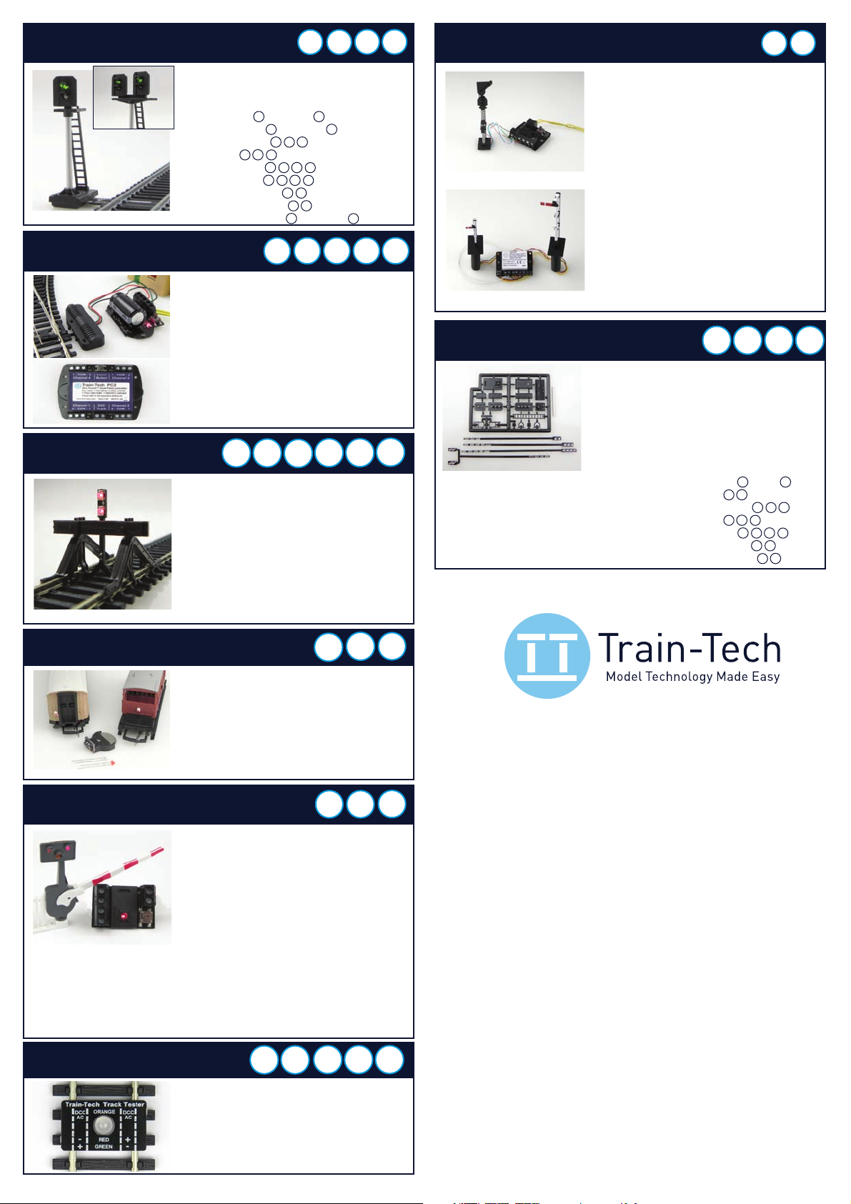
One-Touch DCC™ Signal Controllers
• Control LED & Semaphore signals by DCC
• Easy to set up & use –No CV programming!
• Easy screw terminals – no soldering
• Can sync to other points & signals
DCC
ANY
GAUGE
SC1 Dual 2 aspect colour light signals controller
Controls one or two 2 aspect colour light signals.
Compatible with Train-Tech SK2, SK3, SK7, SK8 and
most other manufacturer’s LED signals
SC2 3 or 4 aspect or 2 aspect+route signal control
Controls one 3 aspect or one 4 aspect or one 2 aspect
+ route signal. Compatible with Train-Tech SK4, SK5,
SK6 and most other manufacturer’s LED signals
SC3 Dual Dapol OO/N Sempahore signal controller
Controls one or two standard OO or N Dapol motorised
semaphore signals by DCC. Signals connect direct to
the SC3 - no modifications or power supply needed.
SC2
SC3
Dapol Signals for photo - not included
Buffer Lights
• Add realistic stop light to any siding
• Simply clips onto track – No wires!
• Fits next to most buffer stops & kits
• Or at platform end or free standing
• Low cost, easy to fit and use
• On DCC both lights are on constantly
• On DC one light is on & varies with speed
• Helps bring your layout to life!
DCCDC
OO
OO
N
HO
HO
BL1 OO/HO gauge Buffer Light
BL2 N gauge Buffer Light
Track and buffer stop not included
HO
HO
OO
OO
N
N
DCC
DCC
DC
DC
Track Tester
Automatic Tail, Firebox, Loco & Coach Lights
• Quickly tests track for power faults
• Low cost and easy to use
• Works on N, TT, OO or HO Track
• Indicates the DC polarity, or DCC, or a fault
• Small enough to check point frogs
• No switch - senses motion & turns on!
• Turns off automatically 4 minutes after stop
• No pickup, wires or soldering - LED plugs in
• Fit in brake vans, coaches, loco, wagons etc
• Runs for ages on small button battery
LFX Lighting Effect Controllers
LFX1 Level Crossing Barrier
Controls Amber and Red LED’s
as seen at level crossings. Can
power up to 4 sets of steady
amber and flashing red LEDs
LFX2 Home & Shop Lighting
Randomly controls lights in houses, shops, stations, pubs
LFX3 Traffic Lights
Controls one pair of timed traffic lights (Tip: You can
adapt one of our Signal kits to make traffic lights)
LFX4 Log or Camp Fires
Controls amber, yellow, red LEDs for a realistic fire effect
LFX5 Welding effects
Realistic electric arc welding effects with bright LEDs
LFX6 Quad LED Lighting Controller
Controls 4 sets of LEDs on and off using separate DCC
addresses. Directly powers 4 LEDs per output (DCC only)
• Add lighting effects to your layout
• LEDs screw in – no resistors or soldering
• Powered by either 12-16V DC or DCC:
• On DC the effect is on when powered
• On DCC the effect can be controlled
LFX1 shown with supplied LEDs fitted
to a Peco barrier kit - not included
ANY
GAUGE
ANY
GAUGE
DCCDC
Self Assembly Colour Light Signal Kits
• Every kit includes the head, post and base
plus detailing kit inc ladder, handrails, etc
• Aluminium ‘post’ included with each kit
• Low cost – adapt to your own design
• Control by switches or a signal controller
TT1 Track Tester
Single output modules:
AL1 Flashing Tail light
AL2 Flame Tail / Firebox
AL3 Constant lighting
LEDs & battery included
Dual output modules:
AL21 Flashing + constant
AL22 Flame + constant
AL23 Sparkarc + constant
AL24 Doors open + constant
DCCDC
OO
Auto
N
HO
SEE WWW.TRAIN-TECH.COM OR CONTACT DCP FOR FREE COLOUR BROCHURE
0313
The LEDs are pre-fitted
onto a long narrow PCB
stick to pass through your
baseboard. Just attach your
signal control wires to PCB
DCCDC
WIRE
FREE
WIRE
FREE
Rolling stock not included
Fits in
N scale
upwards
+
SC1 DCC Signal Controller
Controls two x 2 aspect LED signals
•Control your Signals by DCC controller or PC
• Easy One-Touch DCC™ - no CV programming!
• Works with most LED colour light signals
• Just 2 wires to nearest track - reduces wiring
• Connect Signal LEDs direct - no resistors!
LEDs fade as they change - just like real thing!
•
• Can synchronise to other Signals and points
www.Train-Tech.com
See our website, your local model shop or contact us for a free colour brochure
DCP Microdevelopments, Bryon Court, Bow Street, Great Ellingham, NR17 1JB, UK
Telephone 01953 457800 • email sales@dcpmicro.com • www.dcpexpress.com
 Loading...