

Train-Tech PC200 User Manual
PC200 Point Controller
1!
Please read these instructions fully before connecting and powering up!!
Document Ref D779618/1 DP041117
Introduction
The PC200 is a Point controller designed to control most standard Solenoid type point motors
and offers the following facilities:
•
DCC Control of 4 point motors using DCC accessory commands
•
A Route store to allow multiple points to be changed using a single command
!!• Control of 4 point motors using conventional switches
!!• Built in Capacitor Discharge unit (CDU) for enhanced power
Contents
This instruction booklet explains how to connect, setup and use the PC200 on your layout and
we strongly recommend you read it before starting installation.
!!Connecting power!! ! ! ! Page 2
!!Connecting Point motors!! ! ! Page 3
!!Controlling Points by DCC !! ! ! Page 4
!!Setting up multiple routes!! ! ! Page 5
!!Controlling Points using switches!! ! Page 6
!!Troubleshooting and additional information! Page 7
!
Making it easy….
DCC stands for Digital Command Control and is a system which transmits both power and
digital commands down 2 wires or rails to control and power locomotives and accessories.
At Train-Tech we believe that DCC should make it easier to build, control and use model
railways, so all of our range of DCC Signals, Controllers and accessories connect using just 2
wires and are all setup using just a single button press which we call ‘One-Touch DCC’.
This may be the first accessory you have controlled by DCC and if so you need to be aware that
accessories are controlled by a slightly different command than the locomotives.
Accessory commands are completely different to Loco commands and most DCC hand and
computer linked controllers offer this facility, usually by pressing a specific button to enter into
accessory command mode (eg ACC) or by using a specified range of addresses for accessories
(eg on the Hornby Select addresses over 60 are for accessories only). There are only a few
controllers which do not offer control of DCC accessories including the basic Bachmann EZ
command (as supplied in sets) and Prodigy Express (not the Prodigy Advance which does).
The PC200 can connect directly to the nearest DCC track to minimise wires - it takes both its
commands and power from the rails. As well as changing points, solenoid point motors can also
be used to actuate some semaphore signals & uncouplers (eg Hornby R8244 uncoupler).
The PC200 incorporates a CDU (Capacitor Discharge Unit) which uses a capacitor to store
power from the DCC system for a few seconds and then release it quickly to activate a point
motor with more energy. This means it does not take the large amount of power needed for a
solenoid all at once which might overload your DCC system and just takes a few seconds to
recharge before you can operate a point again. If your route changes more than one Point there
will be a few seconds delay between each change to give the CDU time to fully recharge.
2
•
Connecting to power
Firstly, before installing or connecting any wiring SWITCH OFF ALL POWER!
The PC200 has two screw terminals for the power input and three connections to each point motor
- a common terminal marked COM which should go to one wire of each coil and another 2
terminals marked A & B to each of the other coil connections.
The PC200 is usually mounted underneath the baseboard close to the point motors to keep wiring
as short as possible. There are two mounting holes through the special rivet which also retains the
cover; make sure you do not use screws with a diameter larger than 4mm to hold it in position and
do not mount or stand the PC200 on any metallic or conductive surfaces.
Connecting the PC200 to the power source
The PC200 is usually powered and controlled by DCC, although it can alternatively be powered by
12-16 volts DC if only used for control by switches as shown later in these instructions.
The PC200 can be connected to the nearest DCC rails, bus bar or directly to your controller power
output terminals. Use reasonably thick wire for the connections although the built in CDU will help
store and boost the power to feed the point motors themselves. Before connecting or
disconnecting wires always turn off the power and allow a minute for the CDU capacitors to
discharge and the LEDs to extinguish.
Point Motor cabling
Solenoid Point motors consist of two electromagnets which move a steel bar to actuate a point.
They take a relatively large amount of current (2-3 amps typically) and so to reduce power loss
(which can make point operation unreliable) you should always keep the wires between the point
motor and the PC200 as short and as thick as possible. Bearing this in mind try to locate the
PC200 as close to the points you are controlling as possible so that wires are kept short. Some
point motors are supplied with cables prefitted and these are usually quite short and relatively thin if you need to extend these cables use thicker wire (eg 16/0.2) and keep them as short as possible.
Two-wire Point motors
Some types of solenoid type motors only have two terminals or wires (eg Kato) and these work by
reversing the polarity to activate either coil. These cannot be connected directly to a standard
decoder, although there are third party adapters available which may make them compatible.
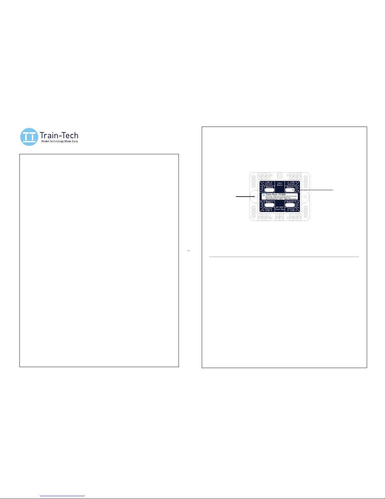
Solenoid 1 Solenoid 2
Solenoid 3Solenoid 4
Power
Input
Learn
button
2 Mounting holes
(4mm maximum
screw diameter)
Areas to write
the main Point
DCC addresses
Switch input
(pages 6/7)
LED1 LED2
LED3LED4
•
Connecting to point motors
3
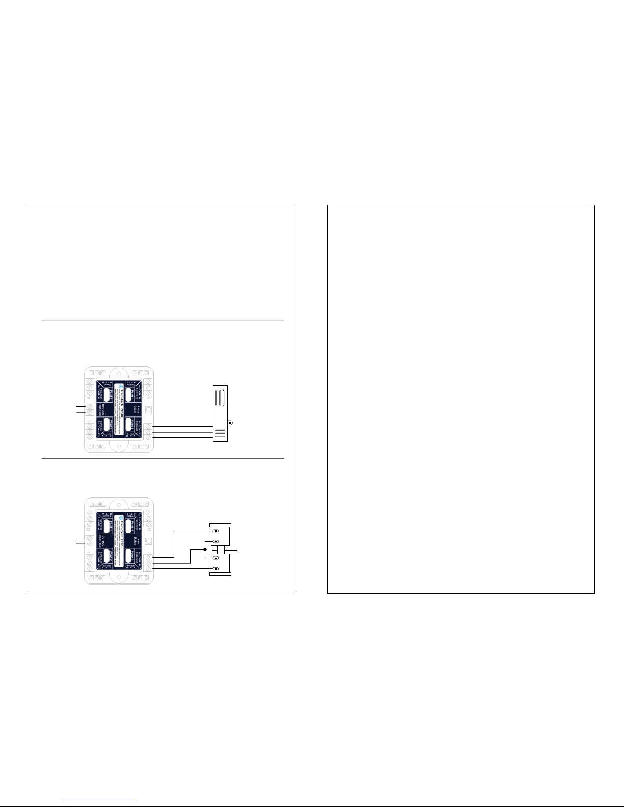
Open frame type point motor
Eg Peco PL10, Hornby R8014, Seep PM-1 etc
Open frame type Point motors (usually fitted on the underside of the baseboard under the point)
Some open frame type point motors have 3 terminals or wires and some have 4. If your point motor
has 4 you will need to connect one of each of the coil terminals together as a common - see below.
DCC
Power In
Connect to
nearest rails or
DCC bus
coil
coil
Solenoid A
Solenoid B
common
Connect a motor to
each of the other 3
outputs of the PC200
in exactly the same way
Surface mount point motor
Eg Peco PL11, Hornby R8243, etc
DCC
Power In
Connect to
nearest rails or
DCC bus
Types of Point motors
There are two main types of solenoid point motors available; Surface mount types which mount on
top of the base board next to the point, and open frame type motors which fit beneath the
baseboard under the point. Although surface mount motors can be easier to fit, generally they are
not as powerful as the larger open frame type which fit under the baseboard. Whichever type of
point motor you choose make sure the point blades and actuator mechanisms all move smoothly
and freely. Note that although the PC200 includes a built in CDU to give the coils a boost, this will
not be enough for a motor to overcome a tight or sticky mechanism. Note that the PC200 is only
suitable for controlling solenoid type point motors, not the motorised ‘tortoise’ type.
Connect your point motor as follows - our examples all show connection to one motor and output
for clarity but the other outputs are connected in exactly the same way. Don’t forget to keep the
wires to the motors as short as possible and use thick cable to connect them. (We recommend
only one point motor should be connected to each output to ensure maximum power is available)
Surface Mount type Point Motors
Surface mounting point motors usually have 3 wires prefitted, one common wire and one for each
of the coils. Note that there is no standard colour code for point motors and they vary between
manufacturers so check the instructions which come with each motor carefully especially if using
more than one make! Eg Hornby and Peco use the same three colours but have different wiring!
Solenoid A
Solenoid B
common
4
• Controlling Points using DCC - one address per point
The PC200 allows you to control points by DCC Accessory commands which are different from
the Loco commands used to control the trains as explained on page 1.
Once the accessory mode is set most controllers use a direction button to send a left or right
command to the accessory, but on some controllers it is buttons 1 and 2. In these instructions we
assume it is a direction control and show it as ▹ or " but you should check the manufacturers
instructions for details on how to control accessories on your particular control system.
The PC200 offers the facility to control points individually using a separate address for each point
and also the facility to store up to 5 different Routes which allow multiple points (on a route) to be
controlled by using just a single command on one address. This page covers the basic setting up
of one address per point and assume you have connected up your PC200 to point motors and the
DCC output or track as per previous pages and that you have familiarised yourself with controlling
DCC accessories using your controller.
SETTING INDIVIDUAL POINT ADDRESSES
Each point needs an accessory ‘address’ assigned to it and with One Touch™ DCC this is very
quick and easy to set up. The PC200 has 4 Point outputs and you can either set them to
consecutive addresses (eg 60, 61, 62, 63) or give each output any arbitrary address you choose.
Initial setting up
• Switch on your DCC controller and power to the track. The 4 LEDs on the PC200 should light up
in sequence. Set up your controller to control DCC accessories (see above).
Setting Point outputs to 4 consecutive addresses
• Set your controller to the DCC accessory address you choose for Point 1 (eg 60)
• Press the ‘Learn button’ on the PC200 once - all 4 LEDs on the PC200 will flash. Then send
either a ▹ or " command from your controller - the LEDs will stop flashing and your PC200
output for Point 1 is now set to the to the address you set (eg 60) & automatically Point 2 is set to
the next address (eg 61), Point 3 to the next (eg 62) and Point 4 to the next (eg 63).
Setting Point outputs to 4 arbitrary addresses
• Set your controller to DCC accessory address you choose for the Point output you wish to set
• Press the PC200 ‘Learn button’ once - all 4 LEDs on the PC200 will flash.
• Press Learn button multiple times until LED next to the Point output you wish to set is flashing.
• Send either a ▹ or " command from your controller - the LED will stop flashing and that point
output is now set to your chosen address (eg 60).
Repeat this procedure for each Point output you want to set - you can do this at any time. Note
that you can give multiple points the same address if you always want them to change together.
Controlling each point
To change a point enter the DCC accessory address you have set up for that point and then send
a ▹ or " command which will change the point - the LED next to that Point output will also flash.
Important note
Note that whichever ▹ or " command you use when you set up the PC200 that command will
always energise the point motor coil which is connected to terminal A, so if you want to change
this just go through the set process again but press the other ▹ or " ‘direction’ command.
(Alternatively you can swap the A / B wires to the solenoid coils over, but above is usually easier)
RESET!
If you wish to change any Point address just repeat the setup procedure or if you wish to fully
reset the PC200 press and hold down the Learn button for 10 seconds. All 4 LEDs will flash in
sequence for a few seconds and then stop. Your PC200 is reset and cleared to original factory
settings which sets the addresses of Point Outputs 1 to 4 to DCC accessory addresses 1 to 4.
 Loading...