

TrainCat Woodchip Loader, 2001901, 1001901 Instructions Manual
Woodchip Loader
Before Starting
PREPARING BRASS The easiest way to remove the brass parts from the sheet they are produced on, is to use rail nippers. The brass is soft and won't affect their
future cutting ability. This will reduce or eliminate the amount of filing to smooth the edge. The next best way is with small sharp diagonal cutters that will fit into the
small areas between the part and the sheet holding them. You should always use a file to remove the balance of the tie. This will ensure a perfect fit.
GLUING BRASS Instant super glues, Cyanoacrylate, CA for short, are very prominent in model building today. They will work perfectly with brass, and they are
instant. We recommend a thick CA glue such as “Zap-A-Gap” from Pacer Technology. As I have also been building R/C airplanes for over 33 years, I have many
airplanes built entirely with CA glue and I can tell you that the wood will break before the glue joint. So it is great stuff! Besides being almost instant, thick CA glues
will help create a small fillet and fill small gaps when applied to the inside of joints. Using a toothpick to apply the CA glue works really well for getting the glue into
the interior areas and controlling the amount of glue used.
PAINTING BRASS Wash your completed assembly in warm soapy water. If it is really messed up with flux etc. you can clean it with a lacquer thinner first. Do NOT
bake the model if you used CA glue for construction. Baking will set the paint to the brass as well as allowing you to paint over parts of it without the first coat
dissolving as you spread on the second coat. One nice thing about painting on brass, if you don't like the paint job you can use paint remover to get rid of it and start
again without hurting the brass.
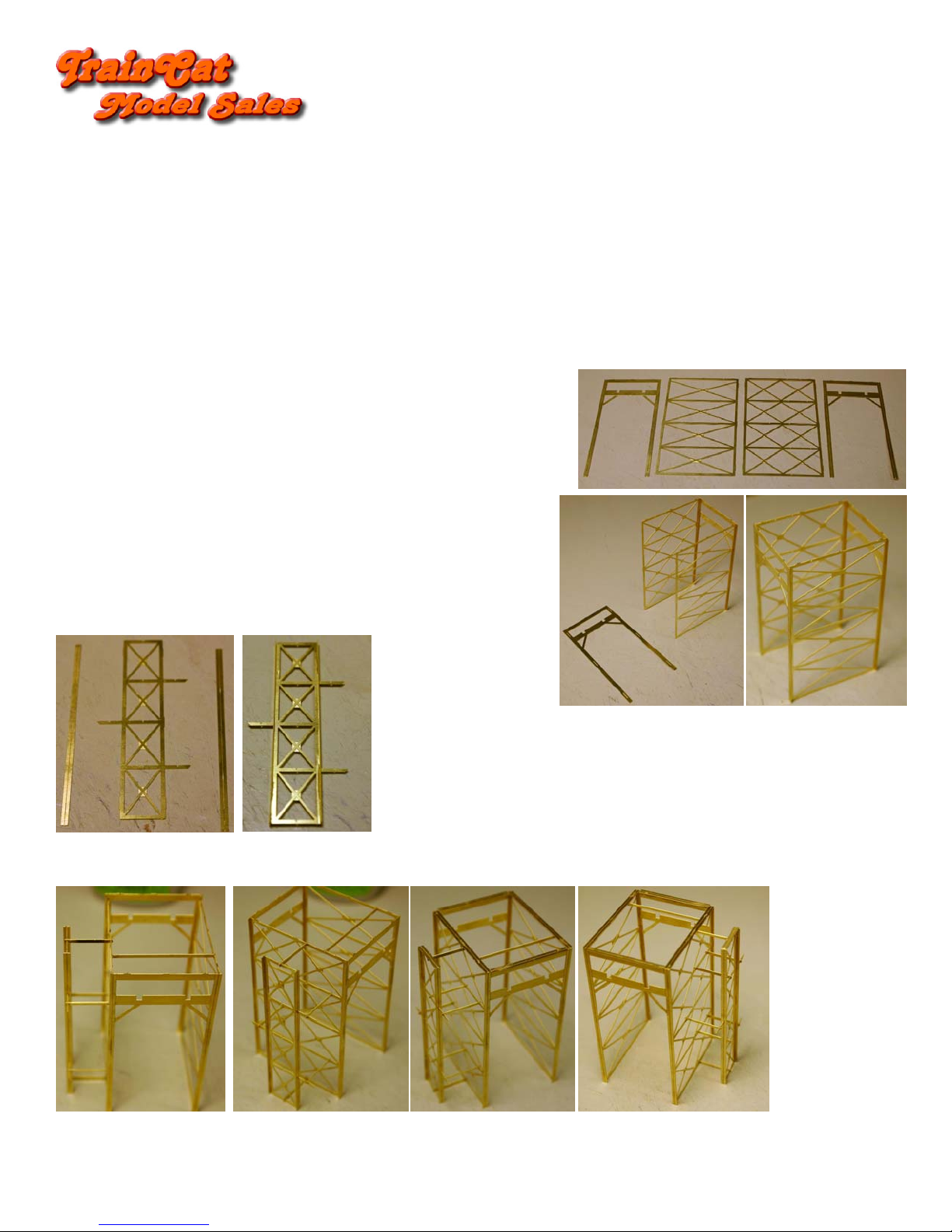
Step #1 – Building The Loading Frame
The main Loader Frame consists of the two Sides and Ends. Remove these from the kit frets and
remove and tie remnants.
There are two different Sides to the frame. The Side with the double X-Bracing be the side that the
Stairs are on. Notice that both Sides have half-etched detail at the X-Bracing center Gussets.
Position the Stair Side tabs into the Frame End slots with the half-etched detail at the X-Bracing
center Gussets facing OUTWARD. Secure the Side to the End.
Now position the other Side tabs into the same Frame End slots with the half-etched detail at the
X-Bracing center Gussets facing INWARD. Secure the Side to the End.
Secure the other Frame End to the assembly.
To build the Stair Support Column, remove the pieces shown from the kit fret and remove all tie
remnants.
Secure the Column Ends on the Frame with the Support Brackets going through the slots in the Ends.
Do both Ends.
The Stair Side of the Frame has several small notches the line-up with notches on the Stair Support Column. Remove the Spacer bars from the fret and connect the Stair
Support Column with the Stair Side by inserting the top and bottom Spacers in the middle of the Column. Leaving the slot empty in the center/middle of the column,
add the remaining Spacers
Add the long spacer between the two Frame Sides. This will be the Walkway support.
Now add the top Cap Strips to the Frame Sides first, then the Frame Ends and finally on the top of the Stair Column.
All Scales
1
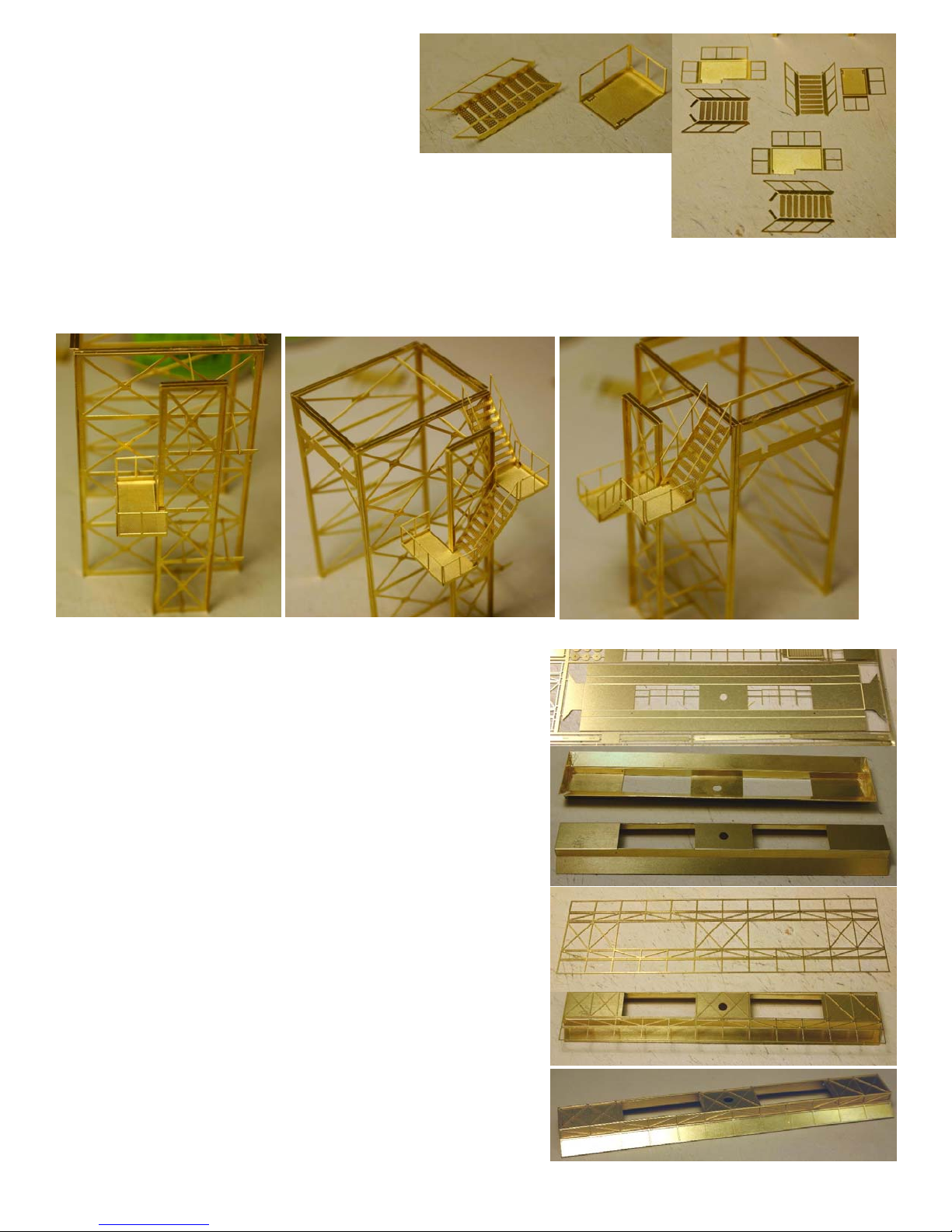
The Staircase has four Stair segments and three Platforms. Remove
the components from the fret and group as shown.
Stairs are built by bending the sides up and pressing on the treads to
the correct angle. Bend all Stairs.
Platforms have either two or three sides. The Platform sides are bent upwards with the bend-line to the inside of the
bend. Bend All Platforms.
Add one of the three sided Platforms to the Stair Column. Ensure the Column Side Cap goes into the Tee-Slot in the
middle of the Platform. Position the Platform so it is perpendicular to the Column and secure.
Add an eight tread Stair with the long tabs the middle three sided stairs on the outside as shown. The bottom of the Stairs has small tabs that go into slots on the
Platform. Once Secure, add the two sided platform to the assembly. The long tabs on the Stairs are secured to the underside of the Platform.
Now add the eight tread Stair that has very small tabs. Be sure the tabs are bent inward 90 degrees to the Stair sides. As before, the tabs on the Stair bottom go into slots
on the Platform. Secure the top of the Stairs to the Frame Side.
Step #2 – Building The Loading Hood
Set aside the Frame Assembly and remove the Loading Hood from the fret. Begin by bending
the sides starting with the bend line closest to the center. This bend will be 90 degrees from the
center of the Hood and you must have the bend on the inside of the bend. Do both sides.
Bend both ends 90 degrees from the center of the Hood. The ends will be used to help with the
last two bends.
Now bend the last side bends outward until the flair angle matches the angle of the ends. Site
down the length of the hood and ensure all bends are straight. Make adjustments if required.
Secure all joints.
If you look back at the prototype image, you will notice that the hood has stiffeners on every
panel. Remove the Stiffener Detail from the fret and remove the end details from the center of
the piece.
The Stiffener Detail piece has a section that will correspond to each panel on the Hood. Small
little tabs hold each section together, but allow the sections to bend to the same angle of the
Hood panels. Carefully align the center of the Stiffener Detail over the center of the Hood so
that the ends match up and the gap for bending is at the edges of the Hood center. Secure the
Stiffener to the Hood first at the Ends and then around the opening in the center of the Hood. I
used a toothpick and small amounts of CA glue to do this.
Bend the Detail over the Hood center and into the bend for the flair. Secure the detail into the
bend for the Hood flair, then along the bottom and side edges.
2
 Loading...