

TrailMax TD-24-T(5+20) User Manual

TD-24-T (5+20)
Table of Contents
Section 1. Operation ............................................................................................... 3
1.0 Introduction ................................................................................... 3
1.1 Purpose ........................................................................................ 3
1.2 Rating ............................................................................................ 3
1.3 Design and Safety Factors ...........................................................4
1.4 Vehicle Load and Handling Limits ................................................ 4
1.5 Alert Symbols ................................................................................ 7
1.6 Uncaging Air Brakes ..................................................................... 8
1.7 Reporting Safety Defects ........................................................... 10
1.8 Pre-Trip Inspection...................................................................... 11
1.9 Hook-Up Procedures .................................................................. 12
1.10 Loading and Unloading ..............................................................13
Trailers With Ramps ................................................................. 14
Trailers With Tilt Decks ............................................................. 14
Section 2. Maintenance ........................................................................................ 15
2.0 Periodic Maintenance ................................................................. 15
2.1 Structural Components ............................................................... 16
Sub-Frame ................................................................................ 16
Deck .......................................................................................... 16
2.2 Sub-Assembly Components .......................................................16
Drawbar Eye ............................................................................. 16
Binkley Jack .............................................................................. 17
Cushion Cylinder ......................................................................17
Deck Latch ................................................................................ 17
Deck Hinge Assembly............................................................... 17
2.3 Rear Impact Guard (RIG) ........................................................... 18
2.4 Running Gear ............................................................................. 19
Suspension ............................................................................... 19
Axle Alignment .......................................................................... 21
Hubs and Drums ....................................................................... 22
Hub Inspection.......................................................................... 22
Broken or Damaged Studs ....................................................... 22
Brake Drum Inspection ............................................................. 23
Brake Drum Troubleshooting Chart.......................................... 24
Brake Drum Troubleshooting Chart (continued) ......................25
Bearing Inspection .................................................................... 26
Bearing Lubrication .................................................................. 26
Seal Inspection and Replacement ...........................................27
Hub Reinstallation and Bearing Adjustment ............................ 27
2.5 Wheels and Tires ........................................................................ 28
Wheels ..................................................................................... 28
Wheel Torquing Procedures ..................................................... 30
Tires .......................................................................................... 31
Inflation Pressure .....................................................................31
Tire Wear Diagnostic Chart ...................................................... 32
®
Table of Contents
page 1
Rev. B 06/27/01

TD-24-T (5+20)
2.6 Electrical .....................................................................................33
Harnesses and Lights...............................................................33
Junction Block ..........................................................................33
Seven-Way Plug.......................................................................33
2.7 Air Brake System ........................................................................34
General Air Brake Maintenance ............................................... 34
Automatic Slack Adjuster Maintenance....................................35
Manual Brake Adjustment ........................................................36
Slack Adjuster Function Test ....................................................37
2.8 Electric Brake System ................................................................. 38
Operation .................................................................................. 38
Using your Brakes Properly...................................................... 39
Synchronization ........................................................................ 40
Controllers ................................................................................ 41
Magnets ....................................................................................41
Brake Cleaning and Inspection ................................................42
Brake Lubrication .....................................................................42
Shoes and Linings .................................................................... 42
Electric Brake System Troubleshooting ...................................43
Measuring Voltage .................................................................... 43
Measuring Amperage ...............................................................45
Manual Brake Adjustment ........................................................46
Electric Brake System Troubleshooting Chart ......................... 47
2.9 Pre-Storage Maintenance ........................................................... 48
2.10 Pre-Season Maintenance ........................................................... 49
Section 3. Parts ..................................................................................................... 50
3.1 Structural Components ............................................................... 50
Sub-frame ................................................................................. 50
Deck Assemblies ...................................................................... 51
3.2 Major Sub-Assemblies ................................................................ 52
Drawbar Eye ............................................................................. 52
Binkley Jack .............................................................................. 53
Cushion Cylinder ......................................................................54
Deck Latch Assembly ............................................................... 55
Deck Hinge Assembly ............................................................... 56
3.3 Rear Impact Guard (RIG) Assembly ........................................... 57
3.4 Running Gear, 12K ..................................................................... 58
Suspension ............................................................................... 58
Axle End Components, 12K ..................................................... 60
Air Brake Components, 12K ..................................................... 62
Electric Brake Components, 12K .............................................64
3.5 Wheels and Tires ........................................................................ 66
3.6 Electrical .....................................................................................68
Harnesses and Lights...............................................................68
Electrical Plug ........................................................................... 70
ABS Electrical ........................................................................... 70
Electric Breakaway System ...................................................... 73
3.7 Air Brake System ........................................................................74
Section 4. Warranty Claim Procedure ................................................................ 78
Table of Contents
®
page 2

TD-24-T (5+20)
Section 1. Operation
1.0 Introduction
This section describes how trailers can have different operational characteristics
based on design, load configuration, gross weights, suspension characteristics, articulation and extreme differences between loaded and unloaded weights.
Trailers have safe operating limits just as automobiles, airplanes, and other vehicles. The interaction of the vehicle characteristics, maintenance, load, roadway,
weather, the skill of the driver and vehicle speed affect these limits. Knowledge of how
these factors affect the vehicle’s operating limits and utilization of defensive driving
techniques should result in safer driving.
1.1 Purpose
The purpose of this section is to describe how the vehicle characteristics, maintenance, road conditions, and weather can affect trailer control and stability limits, and
how driver awareness and skill can help compensate for these factors. This knowledge
will assist you to safely enjoy the maximum utility and productivity from your trailer.
First and foremost, DO NOT operate the trailer until you have read and fully understand this instruction and operating manual. It is also important that each and every
person who operates the trailer be given the opportunity to read this manual.
O
P
E
R
A
T
I
O
N
1.2 Rating
Gross Axle Weight Rating (GAWR) is the rated load-carrying capacity of an individual axle and wheel assembly. It represents the load that may be steadily sustained
by the components in the system; i.e., tires, wheels, hubs, bearings, axles, brakes,
suspension, sub-frame, etc. with the GAWR limited by the component with the lowest
working rating. Consideration of environmental and operational factors may require the
manufacturer to reduce the nominal rating.
Gross Vehicle Weight Rating (GVWR) is the maximum rated combined weight of a
trailer and its payload (uniformly distributed) based on its structural capabilities.
®
Operation
page 3

TD-24-T (5+20)
1.3 Design and Safety Factors
The safety factor is a ratio between the design stress imposed by the load sitting
static on the trailer and the minimum yield stress of the steel used in construction of
that trailer structure. For example, if the structure is built using 50,000 psi minimum
yield strength steel and the load sitting on it causes a stress level of 25,000 psi then a
2:1 safety factor would exist. THIS SAFETY FACTOR DOES NOT MEAN THAT THE
STRUCTURE CAN THEN BE USED TO CARRY TWICE THE RATED LOAD. Under
dynamic conditions, or as the trailer moves and encounters shocks, vibrations, twists
and other conditions that exist during transport, stress levels are elevated far beyond
those in the static situation.
Distributed Load is when a load is distributed evenly over the length of the trailer
deck. This would be considered as the ideal load scenario when fully loaded to rated
capacity.
Concentrated Load is one that is localized over a shorter than normal distance and
imposes greater stress in the concentrated load areas. Under these conditions, it is not
recommended to carry the full rated capacity of the trailer. Extreme concentrated applications may require additional support for the load.
1.4 Vehicle Load and Handling Limits
Vehicle handling limits can be greatly affected by the weight of a load, its placement, the amount of weight distributed over the axles and whether or not the load is
secured properly.
Tow vehicle and trailer combinations are designed to provide maximum directional
control and roll stability within the constraints of highway size and weight limits. Any
combination can be rolled over by driving too fast around a curve, making too abrupt a
maneuver, or by leaving the roadway. Locking up the wheels on an axle can result in a
jackknife or trailer swing out.
One of the major contributing factors to vehicle rollover is high center of gravity on
tall loads. Extreme caution should be used in maneuvering a vehicle and trailer combination, or any unit that has a tall load. Positioning the load in a central side to side
location will enhance directional control, roll stability and braking.
You should be aware that trailers with a shorter wheel base are more prone to roll
during an abrupt lane change or quick reactions at the wheel. This tendency can be
made dramatically worse with a tall, high center of gravity load.
Operation
®
page 4

TD-24-T (5+20)
Overloading a vehicle should never be permitted. Overloading results in tire blowouts, spring breakage, frame damage, diminished braking capacity, and will severely
alter the vehicle’s normal handling characteristics. All vehicles are designed with a
maximum load capability. To best utilize these vehicles in the safest manner the loads
as shown on the certificate label should not be exceeded.
Adequate tongue weight is required for trailers to tow correctly. Inadequate tongue
weight can cause a “whipping action” particularly in shorter wheel base trailers. Too
much tongue weight can overload tow vehicle hitch resulting in reduced steering load
and loss of steering control. Selecting the correct tow vehicle is crucial for the application.
Always maintain enough braking and stopping distance. Erratic or unequal brake
action from side to side on either tow vehicle or trailer can cause handling problems in
braking situations. A balance between tow vehicle and trailer on brake application and
release timing and synchronized pressure will reduce push/pull characteristics which
when excessive, may result in jackknife. The use of properly matched brake lining is
recommended to enhance safer braking.
O
P
E
R
A
T
I
O
N
Proper alignment of both tow vehicle and trailer wheels will add significantly to the
handling characteristics of the combination and allow the driver to utilize all the design
responses of the vehicle to make evasive maneuvers in the safest manner.
Irregular terrain, steep grades and crowned roads, especially rural roadways, freeways, exit ramps, curves, bumps and depressions introduce forces into a tow vehicle/
trailer combination that could result in an accident if proper precautions and driving
techniques are not followed. Even a vehicle that meets all maintenance and load requirements can become hazardous when excessive speeds and certain roadway characteristics are combined.
While on a downgrade, the force of gravity works against the driver in maintaining
control of the vehicle, particularly if the road surface is wet or slick from snow and ice
or loose material. On upgrades, the problem is spinning out due to insufficient traction
at the drive wheels, particularly on snow and ice.
Great care must be taken to avoid excessive use of brakes on long downgrades.
Overheated brakes are dangerously inefficient. It is very dangerous to brake on a
downgrade using only the trailer brakes. If this is done, the trailer brakes heat up and
fade and the tow vehicle brakes alone will not be able to stop the combination by
themselves. Drivers should reduce speed, downshift and use engine compression as
the principal means of controlling speed on long grades and using all brakes so brake
temperatures can be held to a safe level.
®
Operation
page 5

TD-24-T (5+20)
Weather conditions can be a major factor in the cause of accidents. Rain, ice, snow,
high winds and visibility combined with excessive speed, sudden lane changes, or
other factors that put lateral forces into a tow vehicle trailer combination contribute
significantly to an accident.
Slippery roads can increase stopping distances and reduce the ability to control the
vehicle. When the road is wet, the available tire/road friction may be half that of a dry
road, and icy roads can reduce friction many times over wet roads. If hard braking or
rapid acceleration occurs, there may be little or no friction available to prevent tire
lateral movement and skidding results.
The driver has a responsibility to compensate for the characteristics and conditions
of his vehicle, the road conditions and weather. Reducing speeds and increasing attentiveness may compensate for most of these conditions. The more familiar the driver is
with the vehicle and the road, the less likely he will need to make abrupt emergency
maneuvers which will take the vehicle to its limits. Control and stability may be maintained if the driver knows his vehicle, his load, and the road.
Either braking or accelerating while cornering can significantly reduce the controllability and stability of the vehicle and should be avoided. The best driving practice is to
decelerate to a safe conservative speed before entering a corner or approaching congested traffic and then apply only moderate power until an essentially straight path has
been established.
It is imperative that a safe speed always be maintained. The safe speed is that
speed at which control can be maintained over the vehicle at all times. This speed will
allow an emergency change of lane maneuver, travel off an exit ramp with a tightening
radius and recovery from pavement drop-off or wet pavement. This speed will vary from
one combination of vehicle to another and takes into consideration such factors as
road conditions, weather, traffic, visibility, type of load and experience of the driver.
Operation
®
page 6
1.5 Alert Symbols
TD-24-T (5+20)
It is important that you know the meaning of the following symbols that are used
throughout this document.
!
This is the safety alert symbol. It is used to alert you to potential personal injury hazards. Obey all safety messages that follow this symbol to
avoid possible injury or death.
!
DANGER
DANGER! indicates an imminently hazardous situation which, if not
avoided, will result in death or serious injury.
!
WARNING
WARNING indicates a potentially hazardous situation which, if not
avoided, could result in death or serious injury.
SAFETY ALERT!
DANGER!
WARNING!
O
P
E
R
A
T
I
O
N
!
CAUTION
CAUTION indicates a potentially hazardous situation which, if not
avoided, may result in minor or moderate injury.
CAUTION
CAUTION used without the safety alert symbol indicates a potentially
hazardous situation which, if not avoided, may result in property damage.
®
CAUTION!
CAUTION
Operation
page 7

TD-24-T (5+20)
1.6 Uncaging Air Brakes
Air brakes are designed with a safety feature called a spring brake, so that if no air
pressure is present in the system springs will apply force to the brake system linkages
and apply the brakes. To allow the trailer to be moved during shipping a caging key is
installed in each of the spring brake cans to prevent the brakes from being applied.
These keys MUST be removed before the trailer can be put into service.
!
WARNING
The spring brake caging keys must be removed from the spring brake
cans before the trailer is put into service. The brake system WILL NOT
FUNCTION with the keys installed, and the trailer will roll freely until they
are removed.
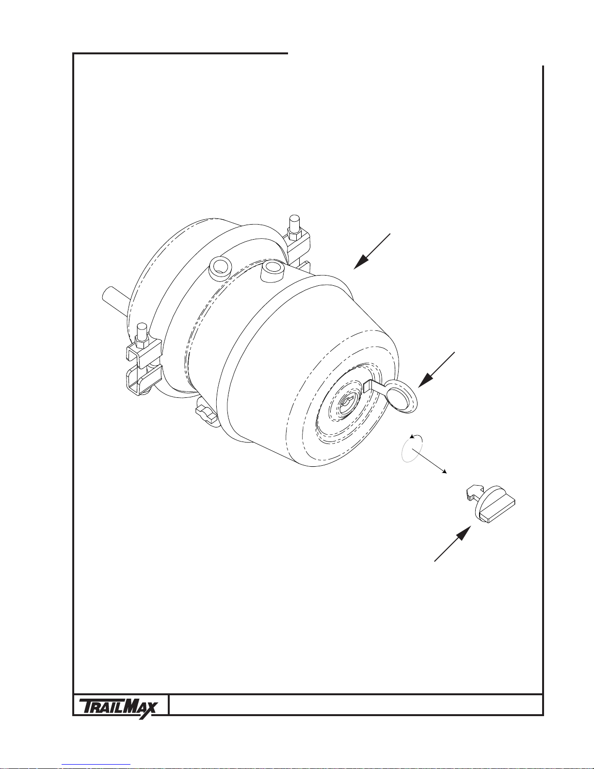
To remove the keys use the following procedure (see illustration on next page):
1. Hook up trailer to tow vehicle, and/or put air to the air brake system on the trailer.
2. Apply approximately 70 psi of air pressure to the brake system; this should be
sufficient to remove the spring pressure and loosen the caging keys.
3. Hold the key and turn the washer behind it until the slots on the washer line up
with the key.
4. Push the key in and turn it approximately 1/4 turn and pull out.
5. Cover the key hole with the attached rubber seal.
INOPERATIVE BRAKE SYSTEM!
6. Repeat this procedure for all spring brake cans.
Operation
®
page 8
TD-24-T (5+20)
Spring Brake Chamber
Rubber Seal
Caging Key
®
Operation
page 9

TD-24-T (5+20)
1.7 Reporting Safety Defects
If you believe that your vehicle has a defect that could cause a crash, injury, or death,
you should immediately inform the National Highway Traffic Safety Administration (NHTSA)
in addition to notifying Gem State Mfg., Inc.
If NHTSA receives similar complaints it may open an investigation, and if it finds that a
safety defect exists in a group of vehicles it may pursue a remedy campaign and recall
those vehicles. However, NHTSA cannot become involved in individual problems between
you, your dealer, or Gem State Mfg., Inc.
To contact NHTSA, you may either call the Vehicle Safety Hotline toll free at 1-888-3274236 (TTY: 1-800-424-9153), go to http://www.safecar.gov; or write to Administrator,
NHTSA, 400 Seventh Street SW., Washington, DC 20590. You can also obtain other
information about motor vehicle safety from http://www.safecar.gov.
Operation
®
page 10

1.8 Pre-Trip Inspection
TD-24-T (5+20)
There are some items on every vehicle combination that can be and should be
inspected prior to every trip that require no special knowledge, training, or sophisticated equipment.
Before beginning a trip, make a thorough visual inspection of the trailer for cracks
in the structure, or bent components such as the tongue or frame. Check for any missing fasteners in suspension as well as other areas, and look for broken or bent springs
and spring hangers or otherwise damaged components.
Verify that the hitch on the tow vehicle is the correct size and configuration to fit the
trailer coupling. The hitch must be rated to meet or exceed the Gross Vehicle Weight
Rating (GVWR) of the trailer.
Check the hitch height of the trailer and compare it to the tow vehicle; it is very
important that the trailer be towed in the level position when loaded. In order to achieve
the correct hitch height, elevate the tongue of the trailer slightly (1" to 2") by adjusting
the trailer hitch to compensate for settling of tow vehicle springs when loaded.
Always visually inspect hitch for unusual appearances such as bent components,
cracks in welds or chipped paint where stress cracks may appear from high loads.
O
P
E
R
A
T
I
O
N
Check tires for proper inflation. Tire manufacturers recommend checking inflation
pressure while trailer is not loaded and tires are cool. This will provide a more accurate
reading. A drop of 10 PSI in tire pressure can reduce the carrying capacity of the tire as
much as 20%. This reduced capacity could cause tire failure and poor tire life.
Maintaining proper wheel nut torque value is essential to prevent wheel end separation or potential damage to the hub or wheel. Always check wheel nuts every 50 to
100 miles for the first 200 miles of operation, then periodically thereafter. The same
procedure should be repeated after dismount and remount of wheels. It is important to
follow the specified tightening sequence recommended in the tire maintenance section
of this manual.
®
Operation
page 11

TD-24-T (5+20)
1.9 Hook-Up Procedures
Connect the tow vehicle to the trailer and check that the coupler is completely latched.
Be sure that a safety pin is inserted to ensure coupler will not unlatch during transport.
Connect the electrical plug from the trailer’s harness to the receptacle of the tow
vehicle. Check all lights on the trailer to make sure they are working correctly with the
tow vehicle’s electrical system.
Be sure the landing leg and drop foot are fully retracted and the crank handle is
stowed in transport position. For trailers with 2-speed jacks, use low gear for raising
and lowering the jack under load, and high gear for raising and lowering the leg when
it is off the ground.
Check all safety chains and their attachment to both the trailer and the towing vehicle. Connect safety chains to tow vehicle using crossed pattern under tongue. Allow
slack for turning, but avoid having chains drag on pavement. Make certain that all
attachment devices are properly installed and in good working order.
For trailers with air brakes, connect the Glad Hands (one service and one emergency) to tow vehicle. Shut off petcock(s) on air tank(s) or if already shut, open to
exhaust all moisture, then shut off. It is very important that the air system be drained of
moisture after each use to keep all components functioning properly and to make equipment safe.
Trailers with electric brakes come equipped with an emergency breakaway device. The breakaway system is designed to operate after the coupling system has failed.
Connect breakaway chain S-hook to bumper or hitch on tow vehicle. Allow slack for
turning, but avoid letting the cable drag on pavement. Provide as straight a connection
as possible.
The breakaway system is for emergencies and is not a parking brake.
Operation
®
page 12
TD-24-T (5+20)
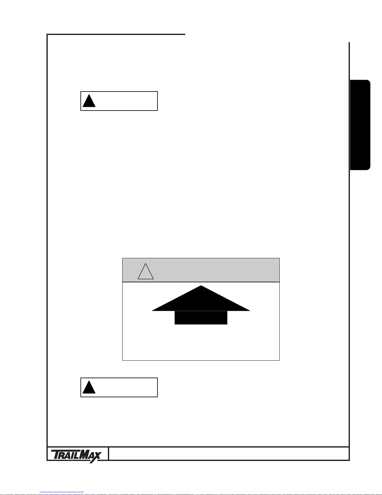
WARNING
!
MAINTAIN 60% OF LOAD
FORWARD OF THIS POINT
(REFER TO OWNERS MANUAL)
1.10 Loading and Unloading
!
CAUTION
The consequences of ignoring proper trailer loading practices can be
very serious. Failure to adhere to the information in this section could
lead to unsafe handling, diminished braking capacity, or other unstable
trailer characteristics which could result in an accident causing property
damage, bodily injury or death.
It is the operators responsibility to take whatever steps necessary to load the
trailer properly, even when it is not easy to calculate the total load or determine
the load center of gravity.
A decal on the trailer similar to the one shown below indicates the correct placement of the load. Load the trailer so that 60% of the total load weight is forward of the
arrow, and 40% is rearward of the arrow. This will ensure that the proper load balance
and tongue weight are achieved.
TRAILER LOADING PRACTICES
O
P
E
R
A
T
I
O
N
!
CAUTION
Adverse weather conditions can cause wet and slippery trailer decks
and ramps. Depending on the type of equipment and typical weather
conditions it may be necessary to add traction aids to the trailer deck and
ramps.
®
ADVERSE WEATHER CONDITIONS!
Operation
page 13

TD-24-T (5+20)
Always use extreme caution when loading and unloading equipment on trailer. Make
sure road surface is level. Loading and unloading on an uneven surface may cause
damage to the trailer frame and create unsafe loading conditions.
Always set brakes on tow vehicle and trailer before loading and unloading and use
chock blocks as an added safety precaution.
Before securing equipment, always lower booms, loaders and buckets. The parking
brake on the equipment being transported must be engaged, where applicable. Always
make sure you are under the maximum allowable height clearance.
Equipment with crawler tracks as well as wheel type equipment should be restrained
in the lateral, forward, rearward and vertical direction using a minimum of four direct
tie-downs and binders each having a working load limit of at least 5000 lbs. and should
be blocked to prevent forward movement.
Articulated vehicles shall be restrained in a manner that prevents articulation while
in transit.
Trailers With Ramps
Loading ramps can be adjusted for various track widths. Prior to loading or unloading it is very important that ramps are adjusted to proper spacing for equipment being
transported. When loading equipment onto deck, drive slowly forward until appropriate
tongue load is achieved. Ramps are designed to support rear of trailer during loading
and unloading. Ramps must be in stored position during transport.
Trailers With Tilt Decks
It is very important that the deck latch is in the locked position with the safety pin
inserted at all times during transport. Always unlock deck when unloading equipment.
Failure to do this may result in damage to deck. Deck latch is adjustable to keep deck
tight and rattle free.
When loading equipment onto deck, drive slowly until deck begins to tilt closed, and
proceed forward until 10% of load weight is on the hitch of trailer. Not enough tongue
weight can result in swaying of trailer, which can be an unsafe condition.
When unloading use reverse procedure as loading. Back up slowly until deck begins to tilt, stop and wait for deck to completely open, then proceed to back off slowly.
Trailer deck will tilt open and tilt closed with one persons weight. The deck may tilt
faster or slower depending on outside temperature, because the temperature affects
the density of the fluid in the deck cylinder.
Operation
®
page 14

TD-24-T (5+20)
Section 2. Maintenance
2.0 Periodic Maintenance
New Trailer Break-in
50 to 100 miles- re-torque wheel nuts- see page 30.
1000 miles- check axle alignment and re-torque suspension fasteners- see page
20.
Pre-Trip Inspection
Lube wear areas on hitch.
Examine frame and tongue members for evidence of damage or cracked welds.
Check suspension for bent or broken springs, damaged components, and loose
or missing fasteners.
Check wheel hub oil levels and for evidence of leaking wheel seals.
Check tire inflation pressures- see page 31.
Check hitch for damage or stress and verify correct hitch height.
Check lights for correct operation.
Quarterly or 3000 miles
Check wheel nut torques- see page 30.
Check brakes for adjustment- air brakes see page 34; electric brakes see page
46.
M
A
I
N
T
E
N
A
N
C
E
Semi-Annually or 6000 miles
Lubricate jack- see page 17.
Re-torque suspension fasteners- see page 20.
Inspect and lubricate brakes and linings- air brakes see page 34, electric brakes
see page 38.
Lubricate tilt deck hinges- see page 17.
Replace wheel bearing lubricant (heavy duty/off-road service)- see page 26.
Annually or 12,000 miles
Replace wheel bearing lubricant (standard duty service)- see page 26.
Special-
Accident or Overload- check all structural components for damage. Check tires
and wheels for damage. Check axle alignment.
Rear Impact- check impact guard components for damage- see page 18.
Skidding- check tires for flat spots.
®
Maintenance
page 15

TD-24-T (5+20)
2.1 Structural Components
Sub-Frame
Other than for periodic or special inspections the trailer sub-frame requires no regular
maintenance other than washing. Keeping the trailer clean will help you notice other
things such as cracked welds or corrosion. If your application requires the hauling of
corrosives then frequent washdowns are very important.
Deck
The deck is the major load-carrying member of the trailer. It requires no regular
maintenance other than a periodic check for broken welds, loose fasteners and corrosion. If the trailer has been overloaded or in an accident, inspect the deck carefully.
It may be necessary to apply a new coat of wood preservative after decking has
aged and become dry. The best time to apply preservative is during warm weather for
better penetration. Replace decking when necessary. Occasionally check for loose,
missing, or broken deck screws.
2.2 Sub-Assembly Components
Drawbar Eye
Check the eye for cracks, loose fasteners and wear. Regularly apply a coating of
grease to the eye to prevent accelerated wear.
The fasteners for the drawbar eye are very important and deserve careful attention.
Replace the bolts if they are damaged in any way, and replace the locknuts if worn.
Torque the fasteners to 315 to 420 lbs.-ft.
Maintenance
®
page 16

TD-24-T (5+20)
Binkley Jack
Every six months, lubricate the jack in the following manner:
1. Extend the leg approximately 2 inches from the fully retracted position.
2. Add 1/4 pound molybdenum grease (with a temperature rating suitable for your
operating conditions) to each of the grease fittings.
The following three sub-sections pertain to trailers with tilt decks-
Cushion Cylinder
The fluid in the cylinder should be changed if the cylinder has leaked or if the deck
action has become jerky or sluggish. Fully collapse the cylinder, and then remove the
filler plug and drain out the old fluid. Add 10W hydraulic fluid until the cylinder is full
and all the air has been expelled.
Deck Latch
The latch assembly is designed with replaceable, self-lubricating bushings at the
wear points. See the appropriate pages of the Parts section of this manual for further
information.
M
A
I
N
T
E
N
A
N
C
E
Should the deck develop a rattle, adjust the hook receiver assembly on the tilt deck.
Deck Hinge Assembly
The hinge assembly is highly stressed during loading and unloading, so check it for
cracked welds frequently.
Every six months, or sooner if service dictates, grease the deck hinges. Apply grease
to the fittings (one per side) until fresh grease becomes visible.
®
Maintenance
page 17

TD-24-T (5+20)
2.3 Rear Impact Guard (RIG)
Your trailer may be fitted with an energy absorbing RIG system that retracts automatically when the deck is tilted for loading and unloading. An elastomeric torsion
block assembly is part of the system and absorbs the excess travel of the retraction
hardware. Normally the RIG requires no maintenance other than checking for loose
fasteners or missing cotter pins.
In the event of a rear impact to the trailer, check the RIG system thoroughly for bent
or damaged components. There are two sacrificial elements in the system called crush
blocks that are intended to deform while absorbing the forces of an impact. If they show
any signs of deformity from having been impacted by the RIG pivot arms, they should
be replaced immediately. In no case should the crush blocks be ‘straightened’ or repaired in any way; they both must be REPLACED if deformed by the RIG pivot arms.
Also check the deck beam flanges that the crush blocks bolt to for damage or bending.
The flanges may have to be straightened if the impact was particularly severe.
Other areas to check include cracked welds, damaged lighting or electrical harness, bent hinge tube or hinge pin, bent retraction push rod, and bent or broken pivot
pins and fasteners. If, after impact, the RIG does not hang normally from the trailer
deck and no other damage can be found, it is possible that the torsion block assembly
has been overstressed and should be inspected and replaced if necessary.
As a last check, tilt the deck while observing the RIG and make sure that it retracts
and extends normally.
Maintenance
®
page 18

TD-24-T (5+20)
2.4 Running Gear
Suspension
The suspension on your trailer is a heavy duty, leaf spring, underslung type. An eye
is formed into the forward end of the longest leaf spring, while the aft end is free to float
against the wear pads of the hangers and rockers. Adjustable spring seats are employed to keep the axles in alignment.
The first maintenance check should be performed after an initial break-in period of
about 1,000 miles. A visual inspection of all suspension components and attachment
welds should be performed to reveal any obvious problems, such as cracks or unexpected wear.
During this ‘walk-around’, it is essential to also check the torque on all suspension
fasteners. In the course of the initial ‘shake down’ period in which the components of
the suspension system ‘seat in’, as much as 25% of the original clamp load on the
bolted joints can be lost. After the parts of the suspension have worked together for a
very short period of time, re-torquing the bolts is necessary to insure that undue movement, which results in excessive suspension wear, does not occur.
During the first maintenance check, the trailers axle alignment should be examined
and adjusted. Alignment should also be checked following any maintenance or repair
procedure performed on the suspension.
M
A
I
N
T
E
N
A
N
C
E
Visually inspect the suspension system every three months or 25,000 miles for
signs of excess wear, elongation of bolt holes, and loosening of fasteners. Whenever
loose or replaced the fasteners in your suspension system should be torqued as detailed below. It is important that you check all bolts and nuts to insure that the recommended torque values are being maintained.
You cannot ascertain these torques values visually or by ‘feel’. USE A TORQUE
WRENCH!
®
Maintenance
page 19
TD-24-T (5+20)
213
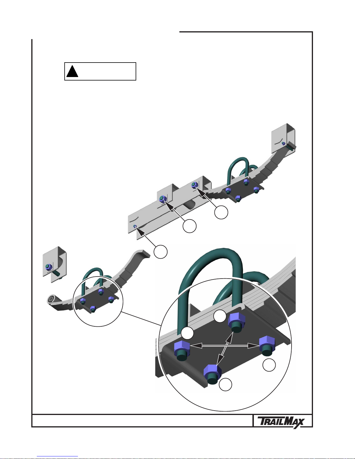
!
WARNING
Follow all torque requirements! Do not use any component with visibly
worn or damaged threads. Failure to follow these safety alerts can lead
to loss of vehicle control, property damage, serious personal injury or
death.
Ref. Item Torque
1. Keeper Bolt 35-45 lb.-ft.
2. Equalizer Bolt 350-400 lb.-ft.
3. Spring Eye Bolt 275-325 lb.-ft.
4.
4.
5
/8" diameter U-bolts 110-130 lb.-ft.
3
/4" diameter U-bolts 130-170 lb.-ft.
TORQUE REQUIREMENTS!
Item #4. Torque U-bolts
in the sequence shown.
Maintenance
2nd
3rd
4th
1st
®
page 20
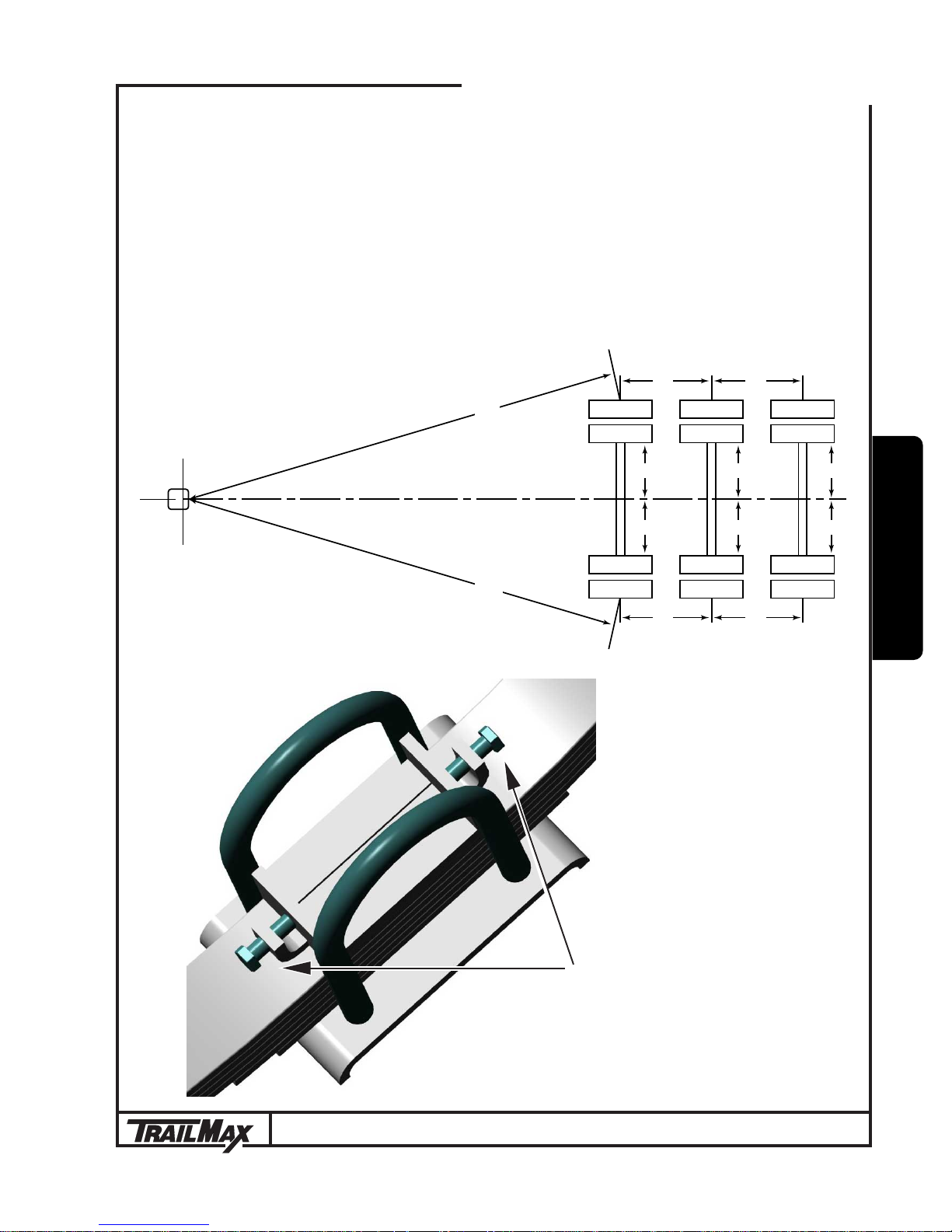
Axle Alignment
TD-24-T (5+20)
Verify that the forward axle is centered on the trailer; W
= W2. Check the distance
1
from the hitch center to the forward axle end on both sides, and adjust the spring seat
adjusters if necessary so that X
is 1/8" less than X2. Next check the W and Z distances
1
for the second axle, and then do the same for the third axle, if so equipped. Try to hold
the measurements to within ± 1/16".
Top View
Right (Curb) Side
X
1
X
2
Left (Road) Side
W
W
Z
1
1
2
Z
2
W
W
Z
3
3
4
Z
4
W
W
5
A
I
N
M
6
T
E
N
A
N
C
E
®
Spring Seat Adjusters
Maintenance
page 21

TD-24-T (5+20)
Hubs and Drums
Hub Removal- Whenever the hub equipment on your trailer must be removed for
inspection or maintenance the following procedure should be utilized:
1. Jack up the wheel. Use a jack stand to support the axle. Only right hand thread
wheel nuts and studs are used on your trailer.
2. Unscrew the polycarbonate oil cap. Have a clean container under the axle to
catch the escaping oil. Examine the oil for evidence of metal particles or foreign matter.
3. Remove the outer jam nut.
4. Remove the lock washer.
5. Remove the inner spindle nut.
6. Remove the hub from the spindle, being careful not to allow the outer bearing
cone to fall out. The inner bearing cone should be retained by the oil seal.
Hub Inspection
Clean the hub with a commercial solvent for inspection. Check for cracks, elongated holes, evidence of overheating or foreign object damage. The hub is crucial to
safe vehicle operation and any doubt about its condition should be cause for replacement.
Broken or Damaged Studs
Typically when a stud is damaged it is due to under torque (loose wheel nuts), over
torque, or overloading. Because the studs act together to share the wheel loads, these
parameters must be followed:
1. If one stud is broken, replace the studs on either side of the broken one also.
2. If two or more studs are broken, replace the entire set.
3. A stud with damaged threads should be replaced immediately.
Maintenance
®
page 22

TD-24-T (5+20)
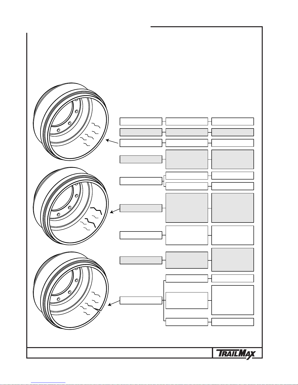
Brake Drum Inspection
Clean and inspect the brake drums whenever relining the brakes. To be suitable for
further service, the brake drum should pass the following checks:
1. The brake surface should be free of scoring, excessive heat checks and free of
cracks.
2. The brake surface diameter should be within the maximum diameter stamped on
the drum.
3. The mounting holes and pilot must be round and true.
4. The mounting surface must be clean and flat.
!
WARNING
If any of the above conditions are not met, the brake drum should be
replaced. Failure to replace the brake drum will result in an unreliable
braking system, and may lead to an accident.
BRAKE SYSTEM SAFETY!
M
A
I
N
T
E
N
A
N
C
E
It may be desirable to machine the braking surface to remove small heat checks or
other surface defects resulting from normal use. The following should be noted when
turning the brake drum:
1. The maximum diameter cast into the back plate portion of the brake drum is the
discard diameter. If any portion of the brake drum exceeds the maximum diameter it
must be replaced.
2. When preparing to machine a drum, allow at least .040" under the maximum
diameter for further normal in-service wear. Failure to allow for service wear will result
in a weakened brake drum and may result in an accident.
Brake drums should be replaced in pairs to achieve the same braking power on
both wheels and maintain even braking load on the axle. Failure to replace both brake
drums on an axle will result in uneven braking load on the axle and may significantly
reduce the performance, service life and/or safety of your vehicle.
See the brake drum troubleshooting charts on the following pages for more information.
®
Maintenance
page 23
TD-24-T (5+20)
Brake Drum Troubleshooting Chart
PROBLEM REMEDYCAUSE
OIL STAINED DRUMS LEAKING SEAL
LIGHT HEAT CHECK NORMAL CONDITION
EXCESSIVE HEAT FROM
BLUE OR DISCOLORED
BRAKE SURFACE
POLISHED BRAKE
SURFACE
HEAVY HEAT CHECK
NOISE, CHATTER, OR
PULSATING BRAKE
FADING OR WEAK BRAKE
DRAGGING BRAKES OR
BRAKE IMBALANCE
BETWEEN TRACTOR
AND TRAILER
NON-ASBESTOS LINING
IMPROPERLY CURED
BRAKE LINING
IMBALANCED BRAKE
SYSTEM, DRAGGING
BRAKES, OR DRIVER
ABUSE. CAUSED BY
CONSTANT HEATING
AND COOLING OF
BRAKE SURFACE.
HEAT SPOTTED,
GREASE STAINED,
OR OUT OF ROUND
DRUM OR LOOSE
BRAKE COMPONENTS
HIGH TEMPERATURES
IN BRAKE SYSTEM, IM-
PROPER ADJUSTMENT,
OR INFERIOR LINING.
REPLACE SEAL. CLEAN
DRUMS & REPLACE LININGS.
MACHINE
MACHINE BRAKE DRUM.
CHECK RETURN SPRINGS
AND FOR BINDING BRAKE
ACTUATION SYSTEM.
NORMAL CONDITION
MACHINE OR DE-GLAZE
WITH EMERY CLOTH
REPLACE BRAKE DRUM.
CHECK BRAKE BALANCE,
BRAKE RETURN SPRINGS,
BRAKE ADJUSTMENT,
AND LINING TYPE WITHIN
VEHICLE COMBINATION.
CHECK BRAKE DRUM
FOR FAULTY CONDITION
AND REMEDY AS
DESCRIBED IN THIS
SECTION
CHECK BRAKE DRUM,
LINING CONDITION, AND
BRAKE BALANCE. AVOID
CONDITIONS OR LOADS
WHICH CREATE HIGH
BRAKE TEMPERATURES.
Maintenance
CRACKED BRAKE DRUM
page 24
MISHANDLING
HEAT CHECKS GROW
AND JOIN TOGETHER
THROUGH DRUM
SECTION
IMPROPER SHOE
CONTACT
REPLACE
REPLACE BRAKE DRUM.
CHECK BRAKE BALANCE,
BRAKE RETURN SPRINGS,
BRAKE ADJUSTMENT,
AND LINING TYPE WITHIN
VEHICLE COMBINATION.
REPLACE. CHECK SHOE
CONTACT AREA.
®
 Loading...