

Page 1
400 W. Artesia Blvd. Fax: (310) 747-3912
Compton, CA 90220 Ph: (877) 695-7812
www.trailmastersuspension.com
FORD F-150 4WD SUSPENSION LIFT KIT
‘09- ’13 KIT# TM403N
WARNING
Installation of a Trail Master suspension lift kit will
change the vehicle’s center of gravity and handling characteristics both on- and off-road. You must drive the vehicle safely! Extreme care must be taken to prevent vehicle rollover or loss of control, which could result in serious injury or death. Avoid sudden sharp turns or abrupt
maneuvers and always make sure all vehicle occupants
have their seat belts fastened.
WARNING
Before you install this kit, read and understand all instructions, warnings, cautions, and notes in this instruction sheet and in the vehicle owner’s manual.
CAUTION
Proper installation of this kit requires knowledge of the
factory recommended procedures for removal and installation of original equipment components. We recommend
that the factory shop manual and any special tools
needed to service your vehicle be on hand during the
installation. Installation of this kit without proper knowledge of the factory recommended procedures may affect
the performance of these components and the safety of
the vehicle. We strongly recommend that a certified mechanic familiar with the installation of similar components
install this kit.
WARNING
Many states and municipalities have laws restricting
bumper heights and vehicle lifts. Consult state and local
laws to determine if the changes you intend to make to
the vehicle comply with the law.
WARNING
The installation of larger tires may reduce the effectiveness of the braking system.
WARNING
Always wear eye protection when operating power tools.
WARNING
Before you install this kit, block the vehicle tires to prevent the vehicle from rolling.
WARNING
DO NOT combine suspension, body, or other lift devices.
Use of vehicle with combined lifts may result in unsafe
and/or unexpected handling characteristics.
WARNING
This kit should only be installed on a vehicle that is in
good working condition. Before you install the kit, thoroughly inspect the vehicle for corrosion or deformation of
the sheet metal. If the vehicle is suspected to have been
in a collision or misused, do not install this kit. Off-road
use of your vehicle with this kit installed may increase
the stress applied to the factory components. Failure to
observe this warning may result in serious personal injury and/or severe damage to your vehicle.
NOTE
Lift height may vary depending on vehicle configuration,
engine size, additional accessories, the factory suspension package, and vehicle’s condition.
NOTE
Trail Master recommends using thread locking compound on the threads of all kit nuts and bolts unless
specified otherwise in these instructions.
Page 2
TM403N
Revised
12.5.13
2
Page 3

Before Starting Installation
NOTE
TM403N
Revised
12.5.13
Wheel & Tire Requirements
Stock 17” & 18” wheels will not work in conjunction with this kit.
Kit parts are prefaced by the word kit and appear in
bold print.
1. Carefully read all warnings and instructions
completely before beginning.
2. Verify all parts have been received in this kit by
checking the parts list at the end of this document.
3. Only install this kit on the vehicle for which
it is specified. If anytime during the installation
you encounter something different from what is
outlined in the instructions, call technical support
at (877) 695-7812.
4. Park vehicle on a clean, dry, flat, level surface
and block tires so vehicle cannot roll in either direction.
5. Measure ride height with the vehicle supporting
its own weight on level ground. To settle the suspension, the vehicle should be driven forward at
least 10 feet immediately prior to taking these
measurements. Ride height is the measurement
from the center of the axle straight up (vertical) to
the fender lip. Record this measurement for all
four wheels.
Fits 2011-UP w/ Electric steering rack.
Torque Specifications:
See factory service manual for torque values
when reusing OE fasteners.
See factory service manual for torque values when re-using
OE fasteners.
Bolt Size Grade 5 (ft.-lbs.) Grade 8 (ft.-lbs.)
1/4”-20 10 10
1/4”-28 10 12.5
5/16”-18 17 22.5
5/16”-24 20 25
3/8”-16 30 40
3/8”-24 35 45
7/16”-14 50 65
7/16”-20 55 70
1/2”-13 75 100
1/2”-20 80 115
9/16”-12 105 135
9/16”-18 115 150
5/8”-11 150 195
5/8”-18 160 210
3/4”-16 175 225
Tire & Wheel Information:
NOTE
Adhere to recommendations when replacement fasteners, retainers and keepers are called out in the
factory service manual. When re-assembling the vehicle it is recommended by the vehicle manufacturer
that certain fasteners are replaced in order to maintain proper retention characteristics. This system
may not include all replacement hardware as recommended by the factory service manual. Additional
replacement hardware should be obtained prior to
installation of this system to meet the requirements
of the factory service manual.
Engine Compartment
1. Disconnect both battery cables. Disconnect
negative cable first, then positive cable.
Due to differences in manufacturing,
dimensions and inflated measurements, tire
and wheel combinations should be test fit prior
to installation. Tire and wheel choice is crucial
in assuring proper fit, performance, and the
safety of your Trail Master equipped vehicle.
For this application, 18” and larger wheel not to
exceed 9” in width with a maximum
backspacing of 5 1/2” is acceptable. A quality
tire of radial design, not exceeding 35” tall X
13.5” wide is recommended. Please note that
the use of a 35” X 13.5” tire may require fender
modification. Violation of these
recommendations will not be endorsed as
acceptable by Trail Master Suspension and will
void any and all warranties either written or
implied.
3
Page 4

TM403N
Revised
12.5.13
Prepare to Install Front
Suspension
1. Place your floor jack under the front
cross member and raise vehicle. Place
jack stands under the frame rails behind
the front wheel wells and lower the
frame onto the stands. Remove the
jack and remove the front wheels.
2. Remove any skid plates if necessary.
3. Work on one side of the vehicle at a
time.
4. Unbolt the OE brake line and bracket
from the side of the knuckle. Save the
hardware for reinstallation.
5. Remove the front caliper and bracket
assembly from the front knuckle by removing the (2) retaining bolts.
NOTE: Make sure you do not let
the calipers hang on the brake lines
or damage will occur.
7. Remove the front rotors from the front
hub.
8. Remove the dust cap and the nut from
the end of the CV in the hub.
14. Remove the upper ball joint nut from
the knuckle and separate using the appropriate tool.
15. Remove the lower ball joint nut, separate using the appropriate tool. Remove the knuckle from the vehicle while
pulling it away from the CV and set the
knuckle aside.
16. Remove the three nuts from the top of
the coil over assembly and the one
large nut and bolt on the bottom. Remove the coil from the vehicle. Save
hardware for reinstallation.
17. Remove the two bolts that retain the
lower a-arms and remove them from
the truck.
18. Repeat on the other side of the vehicle.
19. Mark the driveshaft orientation and
disconnect the front drive shaft from the
differential. Secure the driveshaft up
and out of the way of the work area.
20. Remove the rear cross member brace;
retain (2) of the bolts and nuts for reinstallation.
NOTE: Careful heating of the OE
bolts may be necessary to loosen
the factory thread locker.
9. Remove the anti-lock wiring and sensor
from the hub if applicable.
10. Remove the vacuum line from the rear
of the hub.
11. Disconnect the sway bar end links from
the sway bar. Save hardware for reinstallation.
12. Unbolt and remove the sway bar from
the vehicle. Save hardware for reinstallation.
13. Remove the tie rod end nut and separate from the knuckle using the appropriate tool.
21. Make sure that the front differential is
well supported, remove the existing
hardware from both passenger and
driver side differential mounting areas.
Carefully lower differential out of vehicle
and set aside. Note the vent routing for
reinstall. Be careful the differential is
heavy.
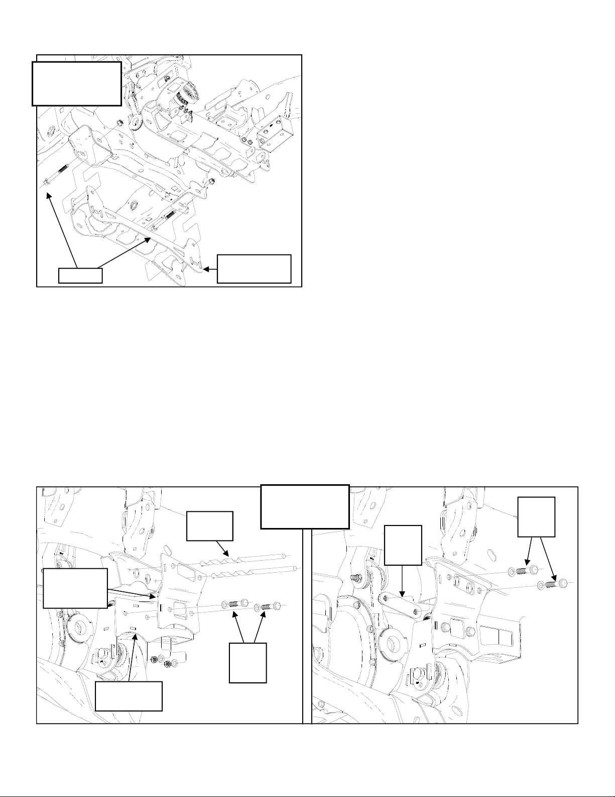
22. In order to install the rear crossmember, the driver side control arm mounting pocket needs to be removed.
Measure up 3 3/4” from the top of the
cam bolt hole and draw a horizontal line
across the entire pocket. See Illustra-
4
Page 5
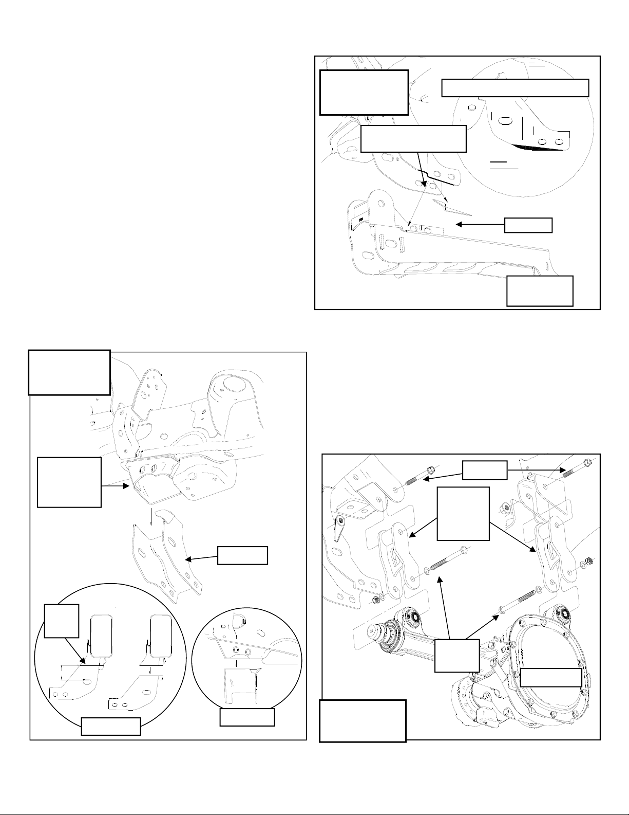
tion 1.
IMPORTANT!: For 2010-UP mod-
els ONLY, the front of the passenger
side rear A-arm pocket will need to
be trimmed approximately 1/4” in order to install the rear crossmember.
See ILLUSTRATION 1a.
23. Using a suitable cutting tool, (abrasive
cutoff wheel, Sawz-all, etc.) cut the
frame along the previously marked lines
as shown in Illustration 1 & 1a (For
2010 Models only). After cutting the
section out of the frame, clean the area
thoroughly and paint the exposed metal
with a good quality paint.
Illustration 1a
Pass Side Frame
Cut
Front of Passenger Side
Rear A-arm Pocket
TM403N
Revised
12.5.13
2010-UP Models ONLY!
1/4”
Cut Piece
82-5504 Rear
Crossmember
Install Front Suspension
Illustration 1
Drvr Side Frame
Cut
Rear
Crossmember
Mounting
Pocket
Cut
Mark
Cut Piece
1. Install the driver side and passenger
side front differential drop brackets 82-
5526 drvr and pass) to the frame with
the previously removed OE bolts and
hardware. Leave the bolts loose. See
Illustration 2.
NOTE: The jog in the brackets will
face towards the front of the truck.
OE Bolt
Front
Diff Drop
Brackets
82-5526
3 3/4”
Front View
Side View
9/16” X
4” Bolt
Differential
Illustration 2
Front Diff Brackets
5
Page 6
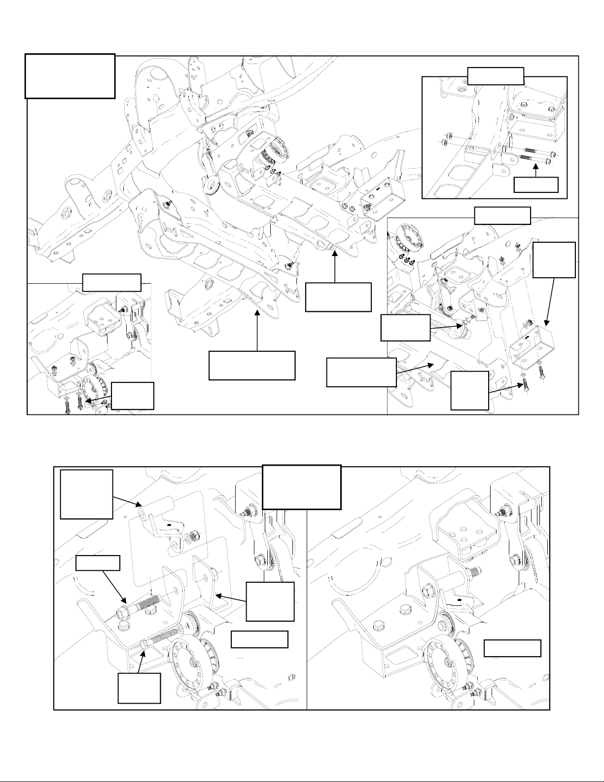
Illustration 3
Rear Crossmember
Install
TM403N
Revised
12.5.13
Pass Side
OE Bolt
Pass Side
82-5518
Sway Bar
Drop
Drvr Side
82-5539
Rear
Differential
Bracket
OE Bolt
7/16” X 1
1/4” Bolt
82-TM241150 Front
Crossmember
Illustration 4
Rear Differential
Mount Install
82-5504 Rear
Crossmember
82-5504 Rear
Crossmember
18mm X
150mm Bolt
7/16” X
1 1/4”
Bolt
9/16” X
4” Bolt
Frame
Mounting
Pocket
Differential
Differential
6
Page 7
TM403N
Revised
12.5.13
Illustration 5
Front Crossmember
Install
TM241150 Front
OE Bolt
Crossmember
2. Carefully hang the differential into the
front differential drop brackets with the
supplied 9/16” X 4” bolts and hardware
from pack (90-6302). Leave the bolts
loose. See Illustration 2.
3. Using the differential drop extension
pack (90-6189) fit the new hose to the
differential. Place the supplied plug in
the end of the tube and connect the factory tube to it. Route the vent hose as
previously noted. Use the supplied zip
ties to secure the hose.
4. Raise the rear crossmember (82-5504)
into place and install the supplied passenger side 18mm X 150mm crossmember bolt. Install the bolt with the
head to the front. Do not install the nut
at this time. See Illustration 3.
5. Install the passenger side sway bar
drop bracket (82-5518) onto the previously installed 18mm crossmember
bolt. Install the nut onto the crossmember bolt. Leave the bolts loose. See
Illustration 3.
6. Secure the passenger side sway bar
drop bracket (82-5518) to the OE sway
bar mounting holes in the frame using
the supplied 7/16” X 1 1/4” bolts and
hardware. Leave the bolts loose. See
Illustration 3.
7. Install the (2) OE crossmember support
brace bolts into the (2) remaining holes
on the pass side of the rear crossmember. Leave the bolts loose. See Illus-
tration 3.
8. Secure the rear crossmember (82-
5504) to the driver side OE sway bar
mounting holes in the frame using the
supplied 7/16” X 1 1/4” bolts. Leave
the bolts loose. See Illustration 3.
82-5516 Rear
Crossmember
Brace
82-5504 Rear
Crossmember
1/2” Drill
Bit
Illustration 6
Rear Crossmember
1/2” X
1 1/2”
Bolt
Brace Install
7
90-5692
Nut
Plate
1/2” X
1 1/2”
Bolt
Page 8

TM403N
Revised
12.5.13
Illustration 7
A-Arm Install
90-5535
Cam Bolt
90-5533
Cam Bolt
Lower
A-Arm
9. Install the rear differential drop bracket
(82-5539) to the differential using the
supplied 9/16” X 4” bolt, through the
mounting hole in the rear crossmember,
with the head facing the rear of the vehicle. Leave the bolts loose. See Illus-
tration 4.
10. Install the front cross member (82-
Illustration 8
Crossmember
Skid Plate Install
Rear
Crossmember
TM241150) into original front A-arm
mounting locations, using the factory
bolts with the heads to the front, leave
loose. See Illustration 5. IMPOR-
TANT!: 2012 –Up models, the bottom
of the A-arm pocket may need to be
trimmed approximately 1/4” in order
to fully install the front crossmember.
11. To ensure proper rear crossmember
placement, test fit the driver side A-arm
in the crossmember mounting pockets.
Secure using the supplied cam bolts
(90-5533 rear and 90-5535 front), cam
eccentric (90-5532), 18mm washers
and nuts.
12. Once the A-Arm is securely in place,
tighten the previously installed 7/16”
hardware and the OE pass side crossmember bolts and hardware. Remove
the A-Arm and cam bolts from the vehicle.
13. Install the rear crossmember brace
(82-5516) to the rear crossmember using the 1/2” X 1 1/2” bolts and hardware. Tighten the bolts. See Illustra-
tion 6.
14. Use the upper holes in the crossmember brace as a guide for drilling through
the frame. See Illustration 6.
15. Center punch and drill the holes using
a 1/2” drill bit. See Illustration 6.
Front
Crossmember
3/8” X 1
1/4” Bolt
3/8” X 1
1/4” Bolt
82-5517
Crossmember
Skid Plate
16. Secure the upper holes in the rear
crossmember brace (82-5516) to the
frame using the 1/2” X 1 1/2” bolts and
nut plate (90-5692). See Illustration 6.
17. Secure the rear upper differential
mount to the frame using the previously
removed OE bolt. See Illustration 4.
18. Install the lower a-arms into the new
cross members with the supplied cam
8
Page 9

TM403N
Revised
12.5.13
Illustration 9
Front Driveshaft Spacer
Front Diff
Flange
Driveshaft
Spacer
90-4248
Front
Driveshaft
Flange
(6) 10mm
X 90mm
12.9 Bolts
bolts (90-5533 front and 90-5535 rear),
cam eccentric (90-5532), 18mm wash-
ers and nuts. The cams should fit between the cam guides on the cross
members. Center the cams in the
guides. You will torque the bolts at the
end of the install when the vehicle is on
the ground. See Illustration 7.
19. Install the crossmember skid plate (82-
5517) to the front and rear crossmembers using the supplied 3/8” X 1 1/4”
bolts and hardware. See Illustration 8.
driveshaft must be clearanced by a
qualified driveline shop.
NOTE: The use of this driveshaft
spacer is intended for light usage
only. If the intended usage is for
high speed off road, this spacer
should not be installed. The factory
front driveshaft should be lengthened by a qualified driveline shop.
Trail Master takes NO
responsibil-
ity for damage caused as a result of
the installation of this spacer.
22. Install the sway bar frame mounts to
the sway bar drop brackets using the
previously removed OE bolt plates,
spacer plates (90-9434), OE and hardware. See Illustration 10.
23. Secure the sway bar end links to the
sway bar using the previously removed
OE hardware.
24. Torque the sway bar mount hardware
to 60 ft./lbs.
20. Torque all differential, sway bar and
crossmember hardware according to
the torque chart on page 18 or to manufacturers specifications.
NOTE: The rear cross member is slot-
ted, the rear cross member needs to be
pushed as far to the Passenger side as possible before it is tightened.
21. Reinstall the front driveshaft to the dif-
ferential by slipping in the new aluminum front driveshaft spacer (90-4248)
and fasten with (6) supplied 10mm– 1.5
X 90mm 12.9 bolts. Be sure to use red
thread locker on these bolts. See Illus-
tration 9. Torque the bolts according to
the chart on page 3. Rotate driveshaft
to check for binding. If it binds the
OE Bolt
Plate
Sway Bar
Illustration 10
Pass Side Sway
Bar Drop
82-5518
Sway Bar
Drop
Bracket
90-9434
Sway Bar
Spacer
Plate
9
Page 10

TM403N
Revised
12.5.13
90-6317
7/16”
Hardware
OE Hardware
82-2977
Coil
Spacer
OE Coil
Over
Shock
Illustration 11
With coil spacer
Notch
to
outside
28. Install the OE bolt through the lower
shock mount and a-arm. Torque to factory specifications.
29. Support the lower A-arms. Position
the new front knuckles. Attach the
knuckle to the lower ball joint.
NOTE: Correctly position and
slide the vacuum actuator over the
CV before the next step.
30. While raising the knuckle and lower
control arm slide the CV through the
vacuum actuator and the knuckle. Attach the nut to the end of the CV
shaft. Torque to 17 ft/lbs. and attach
the dust cap. Torque the small aluminum vacuum cover bolts to 11 ft/lbs.
31. Attach the knuckle to the upper ball
joint. Torque to 85 ft/lbs. Torque the
lower A-arms nut to 111 ft/lbs.
OE Bolt
25. Transfer all the parts from the factory
knuckles to the supplied Trail Master
knuckles (90-4253 drvr and 90-4254
pass) except the vacuum actuator.
NOTE: Tighten all the factory
hardware carefully. Be sure to follow
the factory assembly procedures and
torque specifications.
26. Attach the spacer (82-2977) to the top
of the shock using the previously removed OE hardware. See Illustration
11.
NOTE: The notch in the bottom
ring face toward the outside of the
truck.
27. Install the strut assembly into the strut
mounting locations. Secure using the
7/16” supplied hardware on the top
from hardware pack (90-6317). Torque
to 45-50 ft./lbs. See Illustration 11.
NOTE: Check lower control arm
to CV boot clearance at full droop.
The lower control arm may need to
be trimmed and sanded to prevent
contact.
32. Connect the anti-lock wiring harness
and sensor to the hub if applicable.
33. Install the supplied brake line bracket
(82-7210) to the trailing edge of the
knuckle using the previously removed
OE bolt.
34. Secure the OE brake line bracket on
the front brake line to the new bracket
(82-7210) using the
5/16” X 1” bolt and
hardware.
35. Attach the vacuum lines to the rear of
the hub.
36. Install the front rotors on to the front
hub.
37. Install the front calipers on to the front
rotors by reinstalling the retaining bolts.
Torque to factory specifications.
10
Page 11

TM403N
Revised
12.5.13
NOTE: On 2010-Up models, the
installation of the caliper bolt spacers (90-6736 2 per side) will be necessary to keep the end of the bolts
from contacting the brake rotor.
NOTE: For 2012-Up models, the
brake caliper mounting bracket holes
will need to be drilled out to 5/8”.
Also the casting nubs on the caliper
mounting brackets (the bottom flat
surface near the mounting holes)
may need to be sanded smooth for
brake caliper installation.
38. Install the tie rod end to the knuckle.
Torque to 111 ft/lbs.
39. Repeat the installation on the other
side of the vehicle.
40. Remove stock brake line bracket from
frame. Carefully remount the brackets
with the supplied brake line drops (90-
3202 drvr and pass) in between
bracket and frame. Use factory hardware to fasten the shorter end of the
bracket to the frame. Position the
drops, best for your application. Use
the supplied hardware from pack (90-
6299) to fasten OE bracket to the new
brake line drop.
WARNING!: Make sure the brake
lines that you just modified are not resting against any moving parts.
41. Reinstall the wheels and tires and
lower the vehicle to the ground. Torque
the factory wheels to 150 ft/lbs. If you
are using aftermarket wheels follow the
manufacturers recommended specifications.
component. Use zip ties to secure
these items. At full droop, cycle the
steering from lock to lock while
observing the reaction of these
components. Reposition them if
needed.
45. Reconnect the previously removed
positive and negative battery cables.
IMPORTANT! BE SURE TO BRING
THE VEHICLE IMMEDIATELY TO A
REPUTABLE ALIGNMENT SHOP TO BE
ALIGNED!
IMPORTANT!: AFTER INSTALLATION OF KIT AND BEFORE THE VEHICLE IS FIRST STARTED, BE SURE TO
CENTER THE FRONT WHEELS AND
THE STEERING WHEEL. IF THE FRONT
WHEELS AND THE STEERING WHEEL
ARE NOT CENTERED BEFORE STARTING THE VEHICLE, IT MAY TRIGGER A
DIAGNOSTIC TROUBLE CODE THAT
WILL HAVE TO BE RESET BY THE
MANUFACTURERS SERVICE FACILITY.
NOTE: SEE PAGE 16 FOR STEERING STOP ADJUSTMENT INSTRUCTIONS.
42. Recheck all hardware for proper installation and torque at this time.
43. Torque the 18MM cam bolts to 180-
200 ft/lbs.
44. On both sides of the vehicle, check the
routing of the brake lines and the ABS
wire harnesses. There must be no
pinching, rubbing, or stretching of either
11
Page 12

TM403N
Revised
12.5.13
Prepare to Install Rear
Suspension
1.Block the front tires and raise the rear
of the vehicle. Support the frame with
jack stands forward of the rear springs.
2. Remove the rear wheels.
3. Remove the shocks on both sides of
the vehicle. It may be necessary that you
slightly raise the axle to unload the
shocks for removal.
4. Unbolt the rear driveshaft from the rear
differential. Secure out of the work area.
5. On drivers side, unbolt the existing
brake line bracket from the frame.
6. Install the supplied brake line exten-
sion bracket (82-5502) to the frame using
the previously removed OE hardware.
Then bolt the factory bracket to the new
bracket using the supplied 5/16” X 1”
hardware from hardware pack (90-6314).
7. Reroute rear ABS as necessary use
the supplies zip ties to secure lines.
8. Unhook the emergency brake cable
and remove from OE metal wire clip by
pinching the tangs on the line.
Install Rear Suspension
1.Bolt the supplied emergency brake
bracket (82-7826) to the OE emergency
brake frame bracket using the supplied
1/2” X 1 1/2” Bolt. See Illustration 12.
2. Use the inside hole in the emergency
brake bracket as a guide for drilling
through the frame. See Illustration 12.
3. Center punch and drill the holes using
a 3/8” drill bit. See Illustration 12.
4. Secure the emergency brake bracket
(82-7826) to the frame using the 3/8” X 1
1/2” bolt. See Illustration 12.
5. Slip the cable through new bracket
(82-7826) and re-connect the emergency
brake cable.
Illustration 12
Emergency brake line
drop Bracket
OE
Frame
Bracket
2009-2011 Model Install Shown
E-Brake
Bracket
82-7826
1/2” X 1
1/2” Bolt
9. Support the rear axle with a floor jack
and remove the U-bolts on the driver
side. Loosen the U-bolts on the passenger side.
10. Remove the factory lift block from the
spring assembly. This will not be reinstalled.
12
3/8” Drill
Bit
3/8” X 1
1/2” Bolt
Page 13

TM403N
Revised
12.5.13
NOTE: 2012-Up models will reuse
the previously removed OE metal wire
clip and OE bolt to secure the emergency brake cables to the new
bracket.
6. Install the lift block (95-405F) onto the
axle pad, making sure the pins are fitted
into the holes on the spring perch. Use
your floor jack to raise the axle to the
spring making sure the tabs on the spring
block fit into the holes on the lift block.
See Illustration 13.
7. Secure the assembly with the U-bolts
(13-90390) supplied in hardware pack
and new high-nuts and washers from
hardware pack (20-65302). Do not
tighten the U-bolts at this time. See Il-
lustration 13.
NOTE: Make sure the block sits
flush on the axle perch.
8. Repeat the installation on the other
side of the vehicle.
9. When the installation of the remaining
side is complete, torque the U-bolts to
105 ft. lbs.
10. Insert the supplied sleeves (60859) in
both end of the shocks.
11. Install your new Trail Master shocks
(TM75790W w/ shaft end up ) and
torque this hardware to 66 ft./lbs.
12. Slip in new aluminum rear driveshaft
spacer (90-4338) and fasten with supplied 12mm X 60mm bolts and washers
from hardware pack (90-6493). Be sure
to use thread locker on these bolts. See
Illustration 13
Block install
95-405F
Lift
Block
U BOLT
13-90390
13
20-65302
Hi-Nuts
Page 14

TM403N
Revised
12.5.13
Illustration 14
Rear Driveshaft Spacer
Rear
Differential
(4) 12mm X
60mm Bolts
and Washers
Illustration 14. Rotate the driveshaft to
check for binding. If it binds the driveshaft must be clearanced by a qualified
driveline shop.
Rear
Driveshaft
Driveshaft
Spacer 90-4338
NOTE: The use of this driveshaft
spacer is intended for light usage
only. If the intended usage is for high
speed off road, this spacer should not
be installed. The factory rear driveshaft should be lengthened by a qualified driveline shop.
IMPORTANT!
: Fully cycle the
rear suspension and check for driveshaft plunge. If the driveshaft is too
long it will destroy the transfer case.
Trail Master takes NO
responsibility
for damage caused as a result of the
installation of this kit.
13. Reinstall the wheels and tires and
lower the vehicle to the ground.
14. Reinstall the wheels and tires and
lower the vehicle to the ground. Torque
the factory wheels to 150 ft/lbs. If you
are using aftermarket wheels follow the
manufacturers recommended specifications.
15. Recheck all hardware for proper installation and torque at this time.
14
Page 15

Dynamic Vehicle Check
TM403N
Revised
12.5.13
1. Check steering and suspension in all positions
to ensure that there is no bind and adequate
clearance between all moving, fixed, and heated
members. Check operation of clutch, brake system, and parking brake. Check operation of transmission and transfer case. Ensure there is full engagement in all gears and 4WD ranges. Check
battery connections and electrical component operations. Test-drive vehicle.
WARNING
Re-torque all fasteners after 500 miles and after
off road use. All suspension lift components
should be visually inspected and fasteners retorqued during routine vehicle servicing.
Caution:
Larger wheel and tire combinations increase
stress and wear on steering and suspension
components, which leads to increased maintenance and higher risk for component failure. Larger wheel and tire combinations also alter speedometer calibration, braking effectiveness, center
of gravity, and handling characteristics. Consult
an experienced local off road shop to find what
wheel and tire combinations work best with your
vehicle.
NOTES:
On completion of the installation, have the
suspension and headlights re-aligned.
After 100 miles recheck for proper torque on
all newly installed hardware.
Recheck all hardware for tightness after off
road use.
IMPORTANT!: 18” OR LARGER WHEELS
MUST BE USED IN
CONJUNCTION WITH THIS LIFT KIT!
NOTE
All warranty information, instruction sheets, and
other documents regarding the installation of this
product must be retained by the vehicle owner
Information contained in the instructions and on
the warranty card will be required for any warranty claims. The vehicle owner needs to understand the modifications made to the vehicle and
how they affect vehicle handling and performance. Failure to provide the customer with this
information can result in damage to the vehicle
and severe personal injury.
.
15
Page 16

TM403N
Revised
12.5.13
Steering Stop Shim Adjustment Instructions:
1. After having the vehicle properly aligned by a qualified alignment shop, ensure that
your work space is of adequate size and the work surface is level. Place the vehicle
in park and set parking brake. Place blocks both in front of and behind the rear
wheels.
2. With the vehicle on the ground make sure the steering wheel and the tires are
straight.
3. Turn the steering wheel to full lock left and remove the appropriate shims from the
passenger side front stop and the driver side rear stop until the steering wheel at full
lock is in the same position as Illustration A.
4. Turn the steering wheel to full lock right and remove the appropriate shims from the
driver side front stop and the passenger side rear stop until the steering wheel at full
lock is in the same position as Illustration B.
5. Be sure to use thread locking compound on the 5/16” X 1” shim retaining bolts. See
Illustration C.
Illustration A
Full Lock Left
20 deg.
Full Lock Left
Full Lock Right
Illustration B
Full Lock Right
20 deg.
IMPORTANT!: Any more steering angle than shown in the illustrations may result in CV failure.
16
Page 17

Illustration C
Shim Installation
T
h
C
r
o
e
m
a
d
p
L
o
u
o
n
c
k
d
i
TM403N
Revised
12.5.13
n
g
Steering Knuckle
Steering Stop
Shims
5/16” X 1”
Bolts
Steering Stop Shims
NOTE: This Illustration is just a representation and every application will be different
17
Page 18

TM403N
Box 1 of 4-PN 52209B/52209BMX-1
Revised
12.5.13
Kit Parts List:
Box TM403N-1
82-5504 REAR CROSSMEMBER 1
82-5516 REAR CROSSMEMBER BRACE 1
90-6705 HARDWARE PACK:
70-0501501800 1/2” X 1 1/2” HEX BOLT Gr. 8 2
72-050100816 1/2” STOVER NUT Gr. C
73-05000834 1/2” SAE HARDENED FLAT WASHER - 2 Not Used 4
91-5517 CROSSMEMBER SKID PLATE 1
90-6223 HARDWARE PACK:
70-0371251800 3/8” X 1 1/4” HEX BOLT Gr. 8 4
72-037100816 3/8” STOVER NUT Gr. C 4
73-03700034 3/8” HARDENED FLAT WASHER 8
82-5526 DIFFERENTIAL DROP:
90-6189 HARDWARE PACK:
90-2217 HOSE:
5/16" ID X 3 1/2" 1
90-2216 HOSE MENDER: BRASS (5/16") 1
90-6302 HARDWARE PACK:
70-0561251800 9/16” X 4” HEX BOLT Gr. 8– 1 Not Used 4
73-05600034 9/16” HARDENED FLAT WASHER
72-056100816 9/16” STOVER NUT Gr. C– 1Not Used 4
82-5539 DIFFERENTIAL DROP:
90-6701 HARDWARE PACK:
71-181502501000 18mm-2.5 X 150mm HEX BOLT 10.9 1
72-01810932 18mm-2.5 STOVER NUT Gr. C 1
73-01810934 18mm USS FLAT WASHER 2
90-4248 FRONT DRIVESHAFT SPACER 1
90-6716 HARDWARE PACK:
71-181502501000 10mm- 1.5 X 90mm HEX BOLT 12.9 6
90-6493 HARDWARE PACK:
.120C600HCS1Y 12mm- 1.75 X 60mm 10.9 HEX BOLT 4
73-01200830 12mm SAE FLAT WASHER 4
90-4338 REAR DRIVESHAFT SPACER 1
90-5692 NUT PL ATE: Brace 1
Box TM403N-2
90-4253 KNUCKLE:
Drvr 1
82-2977 COIL SPACER 2
90-6317 HARDWARE PACK:
72-043200810 7/16” GR. 8 HEX NUT 6
73-04300830 7/16” SAE FLAT WASHER 6
Brace 2
- Not Used 2
Skid Plate 1
Front Drvr and Pass 2
Differential 1
Differential 1
– 2 Not Used 8
Rear Drvr 1
Rear Crossmember 1
Front Driveshaft Spacer 1
Rear Driveshaft Spacer 1
Spacer Mount 1
18
Page 19

73-04300836 7/16” SPLIT LOCK WASHER 6
90-6299 HARDWARE PACK:
Front Brake Lines 1
70-0311001500 5/16" X 1" Gr. 5 HEX BOLT 2
72-03100100512 5/16" NYLOCK NUT 2
73-03100030 5/16" SAE FLAT WASHER 4
82-7210 BRAKE LINE BRACKET:
Front Knuckle 2
90-6736 HARDWARE PACK:
62NWHDY/SAEXT
5/8” (thick) Hardened Flat Washer 4
Caliper Bolt Spacers 1
Box TM403N-3
90-4254 KNUCKLE:
Pass 1
95-405F 4" LIFT BLOCK 2
Box TM403N-4
82-TM241150 FRONT CROSSMEMBER 1
82-5502 REAR BRAKE LINE DROP 1
82-7826 EMERGENCY BRAKE BRACKET 1
90-6422 HARDWARE PACK:
E-Brake Bracket 1
70-0501501800 1/2” X 1 1/2 HEX BOLT Gr. 8 1
73-05000034 1/2” HARDENED FLAT WASHER 2
72-0501100816 1/2” NYLOCK NUT Gr. 8 1
90-6314 HARDWARE PACK:
70-0311001800 5/16” X 1” HEX BOLT Gr. 8
72-031100816 5/16” STOVER NUT Gr. C -
Brake Line Drop/ Bump Kit 1
-Not Used 1
Not Used 1
73-03100832 5/16” USS FLAT WASHER -Not Used 2
70-0371501800 3/8” X 1 1/2” HEX BOLT Gr. 8 2
72-037100816 3/8” STOVER NUT Gr. C 2
73-03700034 3/8” HARDENED FLAT WASHER 4
90-6393 HARDWARE PACK:
Front Brake Line Drops 1
90-3202 F150 BRAKELINE DROP 2
90-6299 HARDWARE PACK:
Front Brake Lines 1
70-0311001500 5/16" X 1" Gr. 5 HEX BOLT 2
72-03100100512 5/16" NYLOCK NUT 2
73-03100030 5/16" SAE FLAT WASHER 4
82-5518 SWAY BAR DROP:
Pass 1
90-6340 HARDWARE PACK:
Sway Bar Drop 1
70-0431751800 7/16” X 1 1/4" HEX BOLT Gr. 8 4
72-043100816 7/16” STOVER NUT Gr. C 4
73-04300830 7/16” SAE FLAT WASHER 8
90-6319 HARDWARE PACK:
Zip Ties 1
10999 ZIP TIE, 11", BLACK 12
90-6700 HARDWARE PACK:
90-5532 CAM ECCENTRIC:
90-5533 CAM BOLT– Rear:
90-5535 CAM BOLT– Front:
90-6313 HARDWARE PACK:
Cam Bolts 1
F-150 Slotted 4
18mm-2.5 X 150MM 10.9 2
18mm-2.5 X 160MM 10.9 2
Crossmember 1
TM403N
Revised
12.5.13
19
Page 20

72-01810932 18mm STOVER NUT 4
73-01810934 18mm FLAT WASHER 4
13-90390 U-BOLT:
9/16"-18 x 3.36" x 12.50" 4
20-65302 HARDWARE PACK:
9/16” HI-NUTS 1
90-9434 SWAY BAR MOUNT WASHER PLATE 2
Box TM403N-5
TM75790W 9000 SERIES SHOCK 2
TM403N
Revised
12.5.13
20
Page 21

TM403N
Revised
12.5.13
Revision Page:
21
Page 22

Notice to Owner Operator, Dealer and Installer:
Vehicles that have been enhanced for off-road performance often have unique handling characteristics
due to the higher center of gravity and larger tires. This vehicle may handle, react and stop differently than
many passenger cars or unmodified vehicles, both on and off–road. You must drive your vehicle safely!
Extreme care should always be taken to prevent vehicle rollover or loss of control, which can result in serious injury or even death. Always avoid sudden sharp turns or abrupt maneuvers and allow more time and
distance for braking! Trail Master Suspension
duce speed! We will gladly answer any questions concerning the design, function, maintenance and correct use of our products.
Please make sure your Dealer/Installer explains and delivers all warning notices, warranty forms
and instruction sheets included with Trail Master Suspension
Application listings in this catalog have been carefully fit checked for each model and year denoted. However, Trail Master Suspension
held responsible for misprints, changes or variations made by vehicle manufacturers. Please call when in
question regarding new model year, vehicles not listed by specific body or chassis styles or vehicles not
originally distributed in the USA.
Please note that certain mechanical aspects of any suspension lift product may accelerate ordinary wear of original equipment components. Further, installation of certain Trail Master Suspension
products may void the vehicle’s factory warranty as it pertains to certain covered parts; it is the consumer’s responsibility to check with their local dealer for warranty coverage before installation of the lift.
Warranty and Return policy:
Trail Master Suspension
materials. Trail Master Suspension’s
Trail Master Suspension’s
freight or incidental or consequential damages are expressly excluded from this warranty. Trail Master
Suspension is not responsible for damages and / or warranty of other vehicle parts related or non-related
to the installation of Trail Master Suspension
vehicle with aftermarket components of any kind will assume all risk and responsibility for potential damages incurred as a result of their chosen modifications. Warranty coverage does not include consumer
opinions regarding ride comfort, fitment and design. Warranty claims can be made directly with Trail Mas-
ter Suspension or at any factory authorized Trail Master Suspension dealer.
IMPORTANT! To validate the warranty on this purchase please be sure to mail in the warranty card.
Claims not covered under warranty-
• Parts subject to normal wear; this includes bushings, bump stops, ball joints, tie rod ends and heim joints
• Discontinued products at Trail Master Suspension’s
• Bent or dented product
• Finish after 90 days
• Leaf or coil springs used without proper bump stops
• Products with evident damage caused by abrasion or contact with other items
• Damage caused as a result of not following recommendations or requirements called out in the installation manuals
• Products used in applications other than listed in Trail Master Suspension’s
• Components or accessories used in conjunction with other manufacturer’s systems
• Warranty claims without “Proof of Purchase”
• Trail Master Suspension
or improper maintenance, or improper use of our products.
E-Mail: info@trailmastersuspension.com
Website: www.trailmastersuspension.com
Ph: (877) 695-7812
reserves the right to update as necessary, without notice, and will not be
warranties its full line of products to be free from defects in workmanship and
obligation under this warranty is limited to repair or replacement, at
option, of the defective product. Any and all costs of removal, installation,
accepts no responsibility for any altered product, improper installation, lack of
reminds you to fasten your seat belts at all times and re-
product.
product. A consumer who makes the decision to modify his
discretion
catalog
 Loading...