

Page 1
400 W. Artesia Blvd. Fax: (310) 747-3912
Compton, CA 90220 Ph: (877) 695-7812
www.trailmastersuspension.com
CHEVEROLET/GMC 1/2 TON 4WD SUSPENSION LIFT KIT
‘99- ’06 KIT# TM104N
WARNING
Installation of a Trail Master suspension lift kit will
change the vehicle’s center of gravity and handling characteristics both on- and off-road. You must drive the vehicle safely! Extreme care must be taken to prevent vehicle rollover or loss of control, which could result in serious injury or death. Avoid sudden sharp turns or abrupt
maneuvers and always make sure all vehicle occupants
have their seat belts fas tened.
WARNING
Before you install this kit, read and understand all instructions, warnings, cautions, and notes in this instruction sheet and in the vehicl e owner’s manual.
CAUTION
Proper installation of this kit requires knowledge of the
factory recommended procedures for removal and installation of original equipment compo nents. We recommend
that the factory shop manual and any special tools
needed to service your vehicle be on hand during the
installation. Installation of this kit without proper knowledge of the factory recommended procedures may affect
the performance of these components and the safety of
the vehicle. We strongly recommend that a certified mechanic familiar with the installation of similar components
install this kit.
WARNING
Many states and municipalities have laws restricting
bumper heights and vehicle lifts. Consult state and local
laws to det ermine if the ch anges you intend to make to
the vehicle comply w i th the law.
WARNING
The installation of larger tires may reduce the effectiveness of the braking system.
WARNING
Always wear eye protect i on when operating power tools.
WARNING
Before you install this kit, block the vehicle tires to prevent the vehicle from roll ing.
WARNING
DO NOT combine suspension, body, or other lift devices.
Use of vehicle with combined lifts may result in unsafe
and/or unexpected handling characterist ics.
WARNING
This kit should only be installed on a vehicle that is in
good working condition. Before you install the kit, thoroughly inspect the vehicle for corrosion or deformation of
the sheet metal. If th e veh icle is susp ected to ha ve been
in a collision or misused, do not install this kit. Off- road
use of your vehicle with this kit installed may increase
the stress applied to the fac tory components. Failure to
observe this warning may result in serious personal injury and/or severe damage to your vehicle.
NOTE
Lift height may vary depending on vehicle configuration,
engine size, additional accessories, the factory suspension package, and vehicle’s condition.
NOTE
Trail Master recommends using thread locking compound on the threads of all kit nuts and bolts unless
specified otherwise in these instructio ns.
Page 2
TM104N
Revised
1.27.14
2
Page 3

TM104N
Revised
1.27.14
Before Starting Installation
NOTE
Kit parts are prefaced by the word kit and appear in
bold print.
1. Carefully read all warnings and instructions
completely before beginning.
2. Verify all parts have been received in this kit by
checking the parts list at the end of this document.
3. Only install this kit on the vehicle for which
it is specified. If anytime during the installation
you encounter something different from what is
outlined in the instructions, call technical support
at (877) 695-7812.
4. Park vehicle on a clean, dry, flat, level surface
and block tires so vehicle cannot roll in either direction.
5. Measure ride height with the vehicle supporting
its own weight on level ground. To settle the sus-
Wheel & Tire Requirements
Tire & Wheel Information:
Due to differences in manufacturing, dimensions
and inflated measurements, tire and wheel combinations should be test fit prior to installation. Tire
and wheel choice is crucial in assuring proper fit,
performance, and the safety of your T r a ilmaster
equipped vehicle. For this application, a wheel not
to exceed 9” in width with a maximum backspacing
of 5 1/4” must be used. Addit io nally, a quality tire
of radial design, not exceeding 35” tall X 12.5”
wide is recommended. Please note that the use of a
35” X 12.5” tire may require fender modification.
Violation of these recommendations will not be endorsed as acceptable by Trailmaster Suspension and
will void any and all warranties either written or
implied. 2005 trucks require a 17” wheels to clear
the calipers.
If your truck has a tire pressure sensors on the factory wheels please contact the wheel manufactures
for proper installation and removal.
Factory rims can be used.
pension, the vehicle should be driven forward at
least 10 feet immediately prior to taking these
measurements. Ride height is the measurement
from the center of the axle straight up (vertical) to
the fender lip. Record this measurement for all
four wheels.
NOTE
Adhere to recommendations when replacement fasteners, retainers and keepers are called out in the
factory service manual. When re-assembling the vehicle it is recommended by the vehicle manufacturer
that certain fasteners are replaced in order to maintain proper retention characteristics. This system
may not include all replacement hardware as recommended by the factory service manual. Additional
replacement hardware should be obtained prior to
installation of this system to meet the requirements
of the factory service manual.
Engine Compartment
1. Disconnect both battery cables. Disconnect
negative cable first, then positive cable.
Torque Specifications:
See factory service manual for torque values when
reusing OE fasteners.
See factory serv ice manual for torque value s when re-using
OE fasteners.
Bolt Size Grade 5 (ft.-lbs.) Grade 8 (ft.-lbs.)
1/4”-20 10 10
1/4”-28 10 12.5
5/16”-18 17 22.5
5/16”-24 20 25
3/8”-16 30 40
3/8”-24 35 45
7/16”-14 50 65
7/16”-20 55 70
1/2”-13 75 100
1/2”-20 80 115
9/16”-12 105 135
9/16”-18 115 150
5/8”-11 150 195
5/8”-18 160 210
3
3/4”-16 175 225
Page 4

TM104N
Revised
1.27.14
Important Note
A replacement CV style front drive shaft is recommended for owners who use 4 x 4 Hi range for
extended periods of time.
Vehicles equipped with a 246 transfer case (Auto-trac) will require a replacement CV style front
drive shaft.
Part Number 51256, Standard duty shaft with the slip shaft installed on the drive shaft.
2004 models with traction control and Borg Warner transfer case 4482 may require
Trailmaster driveshaft 51257.
NOTE
Please note that while every effort is made to ensure tha t the installation of your Trailmas ter lift kit is a
positive experience, variations in construction and assembly in the vehicle manufacturing process will
virtually ensure that some parts may seem difficult to install. Add itionally, the current trend in manufacturing of vehicles results in a frame that is highly flexible and may shift slightly on disas sembly prior to
installation. The use of pr y bars and tapered punches for alignment is considered normal and usually
does not indicate a faulty product. However, if you are uncertain about some aspect of the installation
process, please feel free to call our tech support department at the number listed on the cover page. We
do not recommend that you modify the Trailm aster parts in any way as this will void any war ranty expressed or implied by the Trailmaster Suspension company.
Prepare to In st a ll Front Suspe n si on
1. If there are factory skid plates installed, remove them.
2. Measure torsion bar adjusting screw depth and record this dimension for later use when
replacing the torsion adjuster arm on reassembly. Remove the torsion bar adjusting
screw. Apply a small amount of lubrication grease to the puller threads and the puller
shaft-to-adjuster arm contact point. Lo ad puller and torsion adjuster arm until the
adjuster nut can be removed from the cross member. Release the pull er to unload the
torsion bar . With the bar unloaded, slide it forward into the lower control arm until the
adjuster arm falls free. If the bar seems stuck, use a hammer and punch through the
hole in the rear of the cross member to dislodge it. Repeat this procedure on the other
side of the vehicle.
3. Remove the torsion bar cross member by removing the through bolts on each side of
the vehicle. With the cross member out of the way, the torsion bars can be pulled from
the lower control arms and removed. Mark the torsion bars as to their orientation (left
side, right side, and front). They must
be reinstalled exactly as removed! Save these
nuts and bolts for reuse on reassembly.
4. Disconnect the ABS sensor wire and position it out of the way to prevent damage to the
wiring or connector ends. Rem ove brake caliper assembly and securely fasten it awa y
from the wor k area.
4
Page 5

TM104N
Revised
1.27.14
Steps 5 through 12 are performed one side at a time:
5. Remove the 6 bolts that attach the CV axle to the differential. Save these for reuse.
6. Detach the outer end of the tie rod from the spindl e ass em bl y . Special to ols are
available to safely remove these without damage to the joint or the protective boot.
Your GM servic e manual has de ta ils on this proc edure
7. Remove the anti-sway bar links that connect the sway bar to the lower A-arm. Save this
hardware for reuse on reassembly.
8. Remove the shock absorber mounting bolts from the lower A-arm. Save this hardware
for reuse.
9. Remove the upper and lower A-arm pivot nuts. Save this hardware for reuse on
reassembly.
10. Support the A-arm assembly and carefully remove the pivot bolts. Lower the assembly
to the floor and set aside. This assembly is relatively heavy and not a rigid assembly.
Be very careful when removing. Save the pivot bolts for reuse.
11. Remove the upper shock nuts and remove the stock shock absorbers. Discard these
parts.
12. Detach the front driv e shaf t from the diff eren tial yolk and secu re it out of the way.
Disconnect the electro nic sensor and vent line from the differential and secure them out
of the way.
13. Remove the factory bump stops by using a large channel lock type of pliers and discard
the stops.
14. Remove drag link from the pitman arm and idler arm. It may be easier to remove the
Idler arm from the frame with the drag link. Set this assembly aside. Save the nuts for
reuse.
15. Remove the front differential lower mounting bolt. Save this nut and bolt for reuse.
16. Remove the passenger side differential mounting bolts. Save this hardware for reuse.
17. Remove the differential cross member and discard this hardware.
18. While suppor ti ng the diffe re ntial , re mov e th e upper mo un t bolt an d carefully lower the
differential to the ground. Retain this nut and bolt for reuse on reassembly.
19. Using a 2” hole saw without
the pilot drill, r emove the bump s top mount from the frame
on each side of the vehicle. It is important that you do NOT remove any more material
than you have to. Do NOT drill through this pad with the hole saw!
20. Using an angle grinder or equivalent, remove any remaining weld from this area to
achieve a smooth surface.
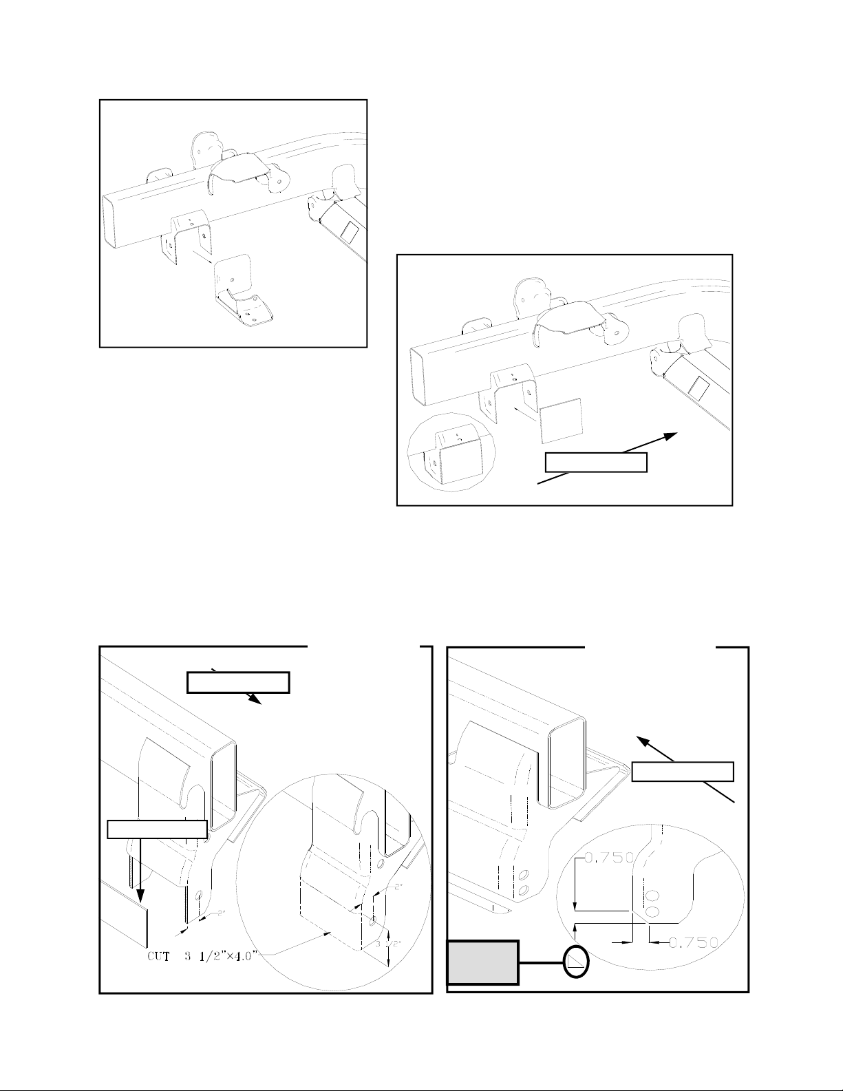
21. Using a re c ip rocating saw or other sui table saw, on the driver side A-arm pocket /
differential mount, cut the rear section out as shown in Illustration A and to the
dimensions shown in Illustration 1.
5
Page 6
A1
TM104N
Revised
1.27.14
Illustration A
A1+A2
Drivers Side
OEM
PN 96-1505
Front of vehicle
Illustration 1
Drivers side.
Front of vehicle
A2
Illustration 2
Passenger side.
Front of vehicle
6
Remove to
clear
Page 7
TM104N
Revised
1.27.14
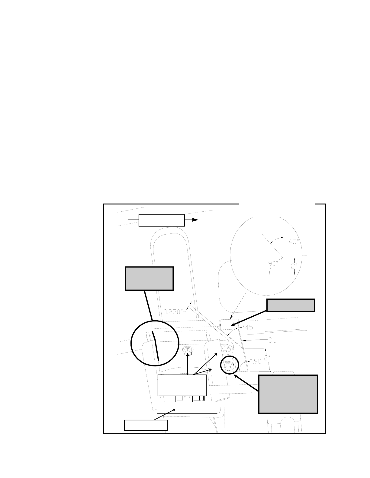
22. On the passenger side mount, cut a 45º section from the pocket as per Illustration 2.
23. On the OEM bump stop flanges on both sides of the truck, cut the front corners to allow
for shock clearance. See Illustration 3.
24. On the front upper A-arm mount pockets, knock the existing alignment cam pins off with
a hammer and grind the surface smooth.
Install Front Suspension
1. Install the provided replacement bump stops (PN 15-11018) to the main cross member
as indicated in Illustration 4. It is important that this is done now as it is not possible to
install these stops after installation of the cross member.
2. With the differential out of the vehicle, temporarily mount the main cross member (PN
82-1459) to the frame using the existing lower A-arm pockets and OEM bolts. Make
sure that the cross member is located with the inside face of the rear flange even with
the rear edge of the OEM bump stop flange as indicated in Illustration 3 (the driver side
should look the same as the passenger side when properly
located). When
the location is
set, clamp the
cross member
to the flanges
to prevent
movement and
drill the 2 upper
mount holes
throug h the
OEM flange on
both sides of
the truck. The
bottom hole is
not accessible
with a drill at
this time, it
must be
marked for later
drilling. Install
provided 3/8” X
1 1/4” NC bolts,
washers and
Stover nuts and
tighten to
prevent
movement.
Repeat this
step on the
Front of vehicle
Important!
See note 3.
3/8” X 1 1/4”
3 places per side
PN 82-1459
Illustration 3
Passenger side.
See note 24.
This hole must be
drilled with the cross
member removed.
See note 4
7
Page 8

passenger side of the truck. On the
driver side, tighten up the bottom OEM
through bolts until there is about 1/16”
clearance between the cross member
and factory pocket sides. Place the
supplied 1/8” X 3 1/2” X 4” plate (PN 96-
1505) across the cutout at the rear of the
pocket, trim if needed and tack weld this
piece in place. These welds must be
sufficiently strong to withstand the
removal of th e cross member for t he next
steps.
Front of vehicle
PN 15-11018
Illustration 4
3. Remove the rear cross member. Finish
welding the replacement plate to the
back of the pocket. Drill the remaining 3/8” holes through the OEM flanges on both
sides of the vehicle. It is important that these bolts are used. Do not skip this step.
Passenger side.
TM104N
Revised
1.27.14
4. Install the differential lowering shackle (PN 82-1446) into the OEM location with the
original nut and bolt. See Illustration 5.
5. Install the passenger side spacer bracket (PN 82-1447) to the OEM mount using the
original hardware. The bracket is slightly tapered. The narrow end of the taper is
oriented to the rear of the truck. Tighten OEM fasteners to specifications. Illustration
6.
6. Hang the differential from the shackle using the supplied 9/16” X 3 3/4” bolt, washers,
and nut. Insert the bolt from the center of the truck to the outside and install the
supplied torque strut as shown in Illustration 5. Install the supplied wash er and lock
nut and tighten the assembly enough so that the strut can be moved without much effort
to complete step 33.
7. Attach the differential to the passenger side spacer bracket as
shown in Illustration
6. Use the supplied
9/16” X 1 3/4” bolts, 2
SAE washers, 2 USS
washers, and nuts.
The USS washers go
onto the slotted
aluminum flange of the
differential. At this
point leave the
fasteners slightly loose
until the main cross
member is back in
place and the torque
strut is positioned.
8. Rotate the differential
torque strut up and to
OEM bolt and nut
PN 82-1446
PN 82-2202
9/16” X 3 3/4”
Illustration 5
Driver side.
Front of vehicle.
1/2” X 1 1/4”
PN 90-1476
8
Page 9

the rear until it is at its closest point to the truck frame as shown in Illustration 5. Mark
the location of the hole. After marking this location, rotate the strut out of the way and
drill this hole to clear a 1/2” bolt. Rotate the strut back into place and install the supplied
1/2” X 1 1/4” bolt through the st rut and through the frame membe r. A 1/ 2” nut plate (PN
90-1476) is supplied to facilitate this installation, position this nut plate over the bolt on
the inside of the A-arm pocket and start the bolt by hand. Leave all hardware loose until
the completion of the cros s member
installation.
9. Reinstall the rear cross member
Front of vehicle.
Illustration 6
Passenger side.
into the truck using the OEM bolts
to hold it in place. Install these
bolts with the threads pointing away
from the CV joints. Make sure to
carefully guide the differential
mounting bushing into it’s mounting
flange on the new c ross member.
OEM hardware
Install the OEM bolt through the
cross member and differential
bushing with the threads to the
outside of the truck and install the
OEM nut. Finish installing the 3/8”
nuts, bolts, and washers to the
upper flange mounts on both sides
PN 82-1447
of the vehicle and torque all cross
member hardware to specifications
USS washers
on page 21. Also tighten the
differential mounting hardware to
specifications at this time.
10. Using the differential dro p ex tensi on
9/16” X 1 3/4”
pack (PN 90-6189) fit the new hose
to the differential. Place the
supplied plug in the end of the tube
and connect the factory tube to it.
TM104N
Revised
1.27.14
11. Install the Trailmas te r cen t er li nk drop (PN 90-21 96) to the pitman arm and idler arm
using the factory nuts. See Illustration 7. When properly installed, the drop is
perpendicular to the ground.
12. Mount the front cross member to the existing front, lower A-arm pockets with the OEM
bolts and nuts. Tighten to specs. Using the cross member as a guide, drill through the
factory frame material at this time. See hi-lighted note in Illustration 7 for the location.
13. Loosely install the OEM center link to the center link drop, with the bends to the rear,
using the supplied 1/2” X 3 3/4” Bolts and other hardware supplied as indicated in
Illustration 7. Leave the lock nuts loose for the moment. Follow this illustration exactly!
14. Install the rod end guide (PN 90-40 53 ) assembli es to the front cro ss memb er as show n
in Illustrations 7 & 9. Use the supplied 1/2” X 2 3/4” bolts, spacers, washers, and nuts.
Place the ends of the rod ends onto the ends of the drop link bolts. Snug up the bolt
9
Page 10

TM104N
Revised
1.27.14
assemblies and rotate the steering assembly back and forth several times to check for
clearance. Additional washers are supplied to facilitate the correction of any
misalignment issues you may encounter. It is very importa nt to ensure no bi n ding
occurs throughout the entire range of motion of the steering assembly. Once correct
clearances are established. Torque all fasteners to specificatio ns .
15. At this point, if you have purchased the optional dual shocks, install the kit per
the enclosed instructions before proceeding to the next step. Leave all hardware
loose, and leave the front mount through bolt out until the next step is complete.
16. Drill out the sway bar mounting threads to clear 3/8” bolts (13/32”). At the front of the
OEM A-arm stop, it will be necessary to grind the existing droop stop tab back enough
to clear the new PN 82-1466 hardware. See Illustration 8. Install the front, upper A-
arm drops to the existing upper pockets using the supplied 9/16” X 1 1/2” bolts (if
installing with the above mentioned shock kit, install using the 9/16” through bolt
supplied with the shock kit) and the 7/16” X 1 1/4” bolts, washers, and nuts from the
bottom of the adapter through the existing holes in the OEM frame. The back holes in
the adapter must be drilled as indicated on Illustration 9. Leave slightly loose until the
sway bar is installed to assure easy insertion of the sway bar mounting hardware.
17. The factory sway bar is remounted upside down using the OEM bushings and mounts.
The mounts are to the original location with spacer (PN 90-1496), supplied 3/8” X 2 1/4”
socket head cap screws, washers, and lock nuts. See Illustration 9. Tighten the
bushing bolts enough to keep the sway bar from swinging but loose enough to facilitate
the installation of the end links.
18. At this point, check all mounting hardware and adapters for correct fit and check all
fasteners to make sure they are in place and correctly tightened.
19. Install the A-arm assemblies on each side of the vehicle by reversing the disassembly
order. Attach the lower A-arm using the supplied 5/8” X 5 1/2” to the rear, 5/8” X 4 1/2”
bolts to the front, washers and nuts. The upper A-arms are installed using the supplied
new
alignment cam (PN 42-778T) assemblies. They are installed with the threads away
from the center of the A-arm. Be careful not to damage the ABS sensor wire. DO NOT
tighten the pivot bolts at this time. For correct positioning of the rubber bushings, the
vehicle should be fully on the ground before these bolts are torqued to specifications.
Note: If there is excessive space between the upper a arm and the new cross
member, shim the space out with the contents of an 90-6275.
20. Install the factory half shafts to the differential with the OEM bolts. Torque to
specifications.
21. Install the sway bar link to the sway bar and lower A-arm with the OEM links. Tighten
until the bushings just start to bulge out. Do not over tighten!
22. Install the front Trailmaster shock absorber (PN TM75551W) to the original position
using PN 90-1079 for the upper mount and the OEM bolts and nuts for the bottom
mount.
23. Install the front drive shaft to the differential.
24. Install the tie rod ends to the steering knuckle and torque to factory specifications.
10
Page 11

PN 82-2196
TM104N
Revised
1.27.14
Illustration 7
Pitman arm
Front of vehicle.
Idler arm
See note 12. This
hole must be drilled.
PN 82-TM20048
1/2” X 3 3/4”
PN 90-4036
PN 90-2055
OEM hardware
Rod End Guides
1/2” X 2 3/4”
1/2” AN washer
See detail illustration 9
11
Page 12

TM104N
Revised
1.27.14
See note 16
5/8” X 4 1/2”
2 per side
9/16” X 1 1/2”
PN 82-1455 driver side
PN 82-1466 passenger side
Illustration 8
Passenger Side View
2 per side
PN 42-778T
Cam bolt kits
5/8” X 5 1/2”
OEM Bolt
12
Page 13

Front of vehicle
PN 90-2014
TM104N
Revised
1.27.14
Illustration 9
Passenger side.
Coupler assembly
PN 90-4053
See note 16. This
hole must be drilled.
Use 7/16” X 1 1/4”
bolts.
PN 90-1496
Illustration 10
Passenger side shown.
Front of vehicle
9/16” X 1 1/2”
2 places.
PN 82-1455 Driver
PN 82-1466 Passenger
3/8” X 2 1/4”
2 places.
13
Page 14

Illustration 11
FRONT BRAKE LINE
BRACKET
PN 90-6303
TM104N
Revised
1.27.14
FRONT BRAKE LINE
DROP PN 90-1868
3/8” X 2 1/2” Bolt
PN 61150
PN 45359
OEM Bushing s
3/8” Nylock Nut
3/8” X 1 1/4” Bo lt
PN 82-2122
Illustration 12
Passenger Side
3/8” USS Washer
PN 90-2039
PN 90-1010
3/8” Nylock Nut
PN 117300007
3/8” NF Nut
14
Page 15

TM104N
Revised
1.27.14
25. Carefully install the front caliper assemblies to each side of the truck.
26. Remove the factory brake line brackets from the frame. Using the supplied brackets
(PN 90-1868) and the previously removed factory bolt attach the new bracket in place of
the stock bracket with the bends facing down. Attach the stock brake line bracket to the
new bracket using the new hardware (PN 90-629 9 ) .
27. Install the ABS sensor wiring and secure them to the brake lines with “zip-ties”. Again,
the harness mu st be r o uted to prevent br e a k age or chaffing. Move the A-arm assembly
up and down to its limits several times to check for binding and to ensure that there are
no interference or pinching problems with the brake lines and ABS wiring.
28. Assemble sway bar end link extensions using hardware from packs (PN 90-6065 and
PN 90-6024) as shown in Illustration 12.
29. Install the sway bar end link extension (PN 82-2122) to the lower control ar m. Using the
OEM bushings and hardware from packs (PN 90-6065 and PN 90-6024). See
IIllustration 12 .
30. Secure the end link assembly to end of sway bar. See Illustration 12.
31. Install the torsion bar cross member drops by locating the new parts (PN 82-5700) in
place as shown in Illustrati ons 13, 14, 15, & 16, and clamping them in place to the
bottom and face of the frame rail. The location is determined by centering the new
adapter holes around the OEM mounting rivets as shown in the detail views. Drill the
four mounting holes per side for clearance of 7/16” bolts. Using the supplied 7/16” X 1
1/4” bolts, fasten the drops to the fr ame rails and torque to specifications.
32. From the factory, there are at least two different configurations for the torsion drop
brackets. Included in the kit are adapters made specifically for these differences. The
primary difference between the cross members is the width. Models with a torsion cross
member width of 40 1/2” (b olt cen te r to bolt center) will use torsio n dro p adapt e rs PN 90-
1638. cross members with a width of 39” will u se PN 90-1636. they are mounted to the
universal adapters previously installed using four 3/8” X 1 1/4” bolts from parts pack PN
90-6223.
33. Install the Torsion bars by reversing the order in which they were removed. Again, be
very careful to install them with the same orientation that they were removed (I.E. left
front to left front, right front to right front)! Reset the preload bolts to the same
measurements previously taken.
34. With the truck still on jack stands and the suspension hanging at full extension, cycle
the steering from lock to lock to check that all components have clearance and operate
freely. Pay very close attention to the ABS wiring and brake lines.
35. Lower the truck to the ground to preload the suspension and unload the upper A– arms.
Tighten the lower A-arm pivot bolts to specifications. It is necessary to rotate the upper
A-arm alignment cam bolts to a neutral position (in the center of the alignment slot) and
then tighten the cam bolts to specifications. This step is necessary to allow you to get to
a professional alignment shop only! Do not assume that this setting is “close enough”
and skip the alignment.
15
Page 16

TM104N
Revised
1.27.14
Illustration 13
7/16” X 1 1/4”
PN 82-5700
3/8” X 1 1/4”
Illustration 14
PN 82-5700
PN 90-1636
PN 90-1638
PN 90-2011
PN 15-11149
OE Bolt
Illustration 15
Drivers Side.
Illustration 16
Complete, Drivers Side.
16
Page 17

TM104N
Revised
1.27.14
Prepare to Install Rear Suspension
1. Raise the rear of the truck enough for the tires to clear the ground and use jack stands on the frame to support
the truck. Remove the rear tires and wheels.
2. Carefully remove the OEM shock absorbers. It may be necessary to raise the differential housing slightly to
facilitate their removal.
3. Remove the factory bump stops from the vehicle.
4. One side at a time, support the differential housing on the side being modified. Remove the “U” bolts from that
axle end and discard. Carefully lower the differential away from the OEM springs. Remove and discard the
OEM riser block from its mount pad. Take careful note of the position of the factory spring packs.
Install Rear Suspension
1. ADD-A-LEAF (13125-1) INSTALLATION NOTE: In order to properly install the add-a-leaf spring, it will be
necessary to contain the elasticity in the leaf spring wit h “C” cla mps whe n the center bolt is removed.
Some springs have a factory helper spring consisting of one or more flat leaves install ed at the bottom
of the leaf pack. DO NOT install the add-a-leaf spring in or below the helper spring.
2. Hold the spring assembly securely together with “C” clamp. If necessary remove any spring leaf alignment
clamps. Remove the spring center bolt. A hammer and drift punch may be used to drive it out if necessary.
3. Carefully remove “C” clamps and lay unassembled leaves aside.
NOTE: Add-a-leaf will be placed in the spring assembly progressively according to length. For
example, if the existing leaves are 32” long and 25” long and the add-a-leaf is 28” long, pl ace the add-aleaf between the existing leaves.
4. Apply a small amount of grease to the end of the add-a-leaf, place it in the spring assembly as described in the
note above, and reassemble the leaf springs using the “C” clamps also insert the new center bolt (PN 97-380)
and torque the center bolt nut to 20 ft./lbs. With a hacksaw, cut the center bolt even with the top of the nut.
5. Loosely assemble the complete spring assemblies into their respective axle mounts. As shown in
ILLUSTRATION 19, place the (PN 95-401) blocks in position. Make sure the pin in the block is in the hole of the
axle housing spring pad. The short end of the block goes toward the front of the vehicle. Install the block so the
pinion moves up.
6. If you are installing an optional traction bar kit, install the riser block as is. If you are not using the traction bars, it
will be necessary to grind off approximately 1/4” of the locating dowel. Make sure after grinding that you test fit
the riser block to ensure it fits the axle housing without interfering with the axle tube. Install the new 4” riser
block, short end to the front, to the mount pad on the axle housing and raise the axle housing until the riser block
hole fits around the new leaf spring center bolt.
7. Install the new “U” bolts over the leaf spring assembly and using the new washers and nuts supplied along with
the existing spring plates, torque the U-bolt nuts to 105 ft./lbs. See Illustration 19.
8. Install the bump stop extensions provided (PN 82-2144). See Illustration 17.
9. Repeat these steps on the other side of the vehicle.
10. Before installing your new Trailmaster shock absorbers (PN 75870W), it is necessary th at you check f or
adequate clearance. Temporarily install your Trailmaster shocks into the shock mounts. Carefu lly check f or
clearance issues. If there are areas that come in contact with or are very close to your new shocks, carefully
remove sufficient material to ensure trouble free operation. Pay particular attention to the area around the lower
shock mount. When all clearance issues have been res olved , inst a ll your new Trailmast er shock absorbe rs and
recheck all fasteners for proper installation and torque. See Illustration 18.
11. Install your wheels and tires and l ower the vehicle to the ground.
12. After installation is complete, double check that all nuts and bolts are tight. Refer to the chart at the end of this
document for torque specifications. (Do not retighten nuts and bolts where thread locking compound was used).
17
Page 18

Illustration 17
PN 82-2144
TM104N
Revised
1.27.14
3/8” X 1 1/4”
Illustration 18
1/2” X 2 3/4”
OEM bolt
PN 97-380
PN 95-401
Shock #
TM75870W
Shock Sleeve
PN 13-90087
Add-A-Leaf
PN 13127-1
Illustration 19
18
Page 19

Kit Parts List:
Box TM104N-1
13-90087 9/16” U-BOLT 4
20-65302 HARDWARE PACK 1
13-30330 9/16” FLAT WASHER 8
13-10423 9/16” HIGHNUT 8
82-TM20048 FRONT CROSS MEMBER 1
90-1496 SWAY BAR SPACER 2
82-2144 BUMP STOP SPACER 2
82-2202 DIFFERENTIAL TORQUE TUBE 1
90-6158 HARDWARE PACK 1
90-2055 1/2” ID X 1 1/2” OD X 3/8” SPACER 2
90-2014 SPACER, 3/4” OD X 1/2” ID X 1/4” 2
90-4053 5/8” COUPLER 2
96-4036 STEERING CONE REDUCER 4
90-6173 HARDWARE PACK 1
70-0372251543 3/8” X 2 1/4” NC SOCKET HEAD CAP SCREW 4
73-03700034 3/8” SAE GR 8 FLAT WASHER 8
72-03700100816 3/8” NC SELF LOCKING NUT 4
70-0503751800 1/2” X 3 3/4” NC GR 8 HEX BOLT 2
73-05000038 1/2” GR 8 AN FLAT WASHER 10
70-0624501800 5/8” X 4 1/2” NC GR 8 HEX BOLT 2
73-06200034 5/8” SAE GR 8 FLAT WASHER 4
72-06200100816 5/8” NC SELF LOCKING NUT 2
70-0502751800 1/2” X 2 3/4” NC GR 8 HEX BOLT 2
73-05000034 1/2” GR 8 FLAT WASHER 4
72-05000100816 1/2” NC SELF LOCKING NUT 4
95-401 CAST IRON LIFT BLOCK 2
96-1505 WELD PLATE 1
90-6303 HARDSWARE PACK: FRONT BRAKE LINE 1
90-1868 FRONT BRAKE LINE DROP 2
90-6299 HARDWARE PACK 1
90-6189 HARDWARE PACK: DIFF VENT 1
82-2122 SWAY BAR END LINK 2
90-6024 HARDWARE PACK, SWAY BAR 1
70-0371501500 3/8” X 1 1/2” USS GR 5 2
70-0372501500 3/8” X 2 1/2” GR 5 HEX BOLT 2
72-03700100512 3/8” USS GR 5 NYLOC NUT 4
73-03700030 3/8” SAE FLAT WASHER 4
73-03700042 3/8” USS HARD ENED FLAT WASHER 2
TM104N
Revised
1.27.14
19
Page 20

90-6065 HARDWARE PACK, SWAY BAR 1
90-1010 BRACKET, SWAY BAR FRONT MOUNT 2
117300007 WASHER, RETAINER 4
45359 HOURGLASS BUSHING, BLACK 2
61150 SLEEVE, 5/8” X 1.48” LG. 2
90-2039 SLEEVE, 5/8” X .25 LG. 2
8337-1 3/8” SAE HEX NUT 2
Box TM104N-2
82-1446 DIFFERENTIAL DROP, DRIVER SIDE 1
82-1447 DIFFERENTIAL DROP, PASSENGER SIDE 1
90-6223 HARDWARE PACK, TORSION DROP ADAPTERS 1
70-0371251800 3/8” X 1 1/4” NM GR 8 HEX BOLT 4
72-03700100816 3/8” NC SELF LOCKING NUT 4
73-03700034 3/8” SAE GR 8 FLAT WASHER 8
82-5700 TORSION BAR DROP, BASE 2
90-1636 TORSION DROP ADAPTER, CHEVY/GMC 02 2
90-1638 TORSION DROP ADAPTER, CHEVY/GMC 99-01 2
82-1455 UPPER A-ARM DROP, DRIVER SIDE 1
82-1466 UPPER A-ARM DROP, PASSENGER SIDE 1
82-2196 CENTER STEERING LINK 1
90-6172 HARDWARE PACK 1
70-04312518 00 7/16” X 1 1/4” NC GR 8 HEX BOLT 4
73-04300034 7/16” SAE GR 8 FLAT WASHER 8
72-04300100816 7/16” NC SELF LOCKING NUT 4
70-05615018 00 9/16” X 1 1/2” NC GR 8 HEX BOLT 4
70-05637518 00 9/16” X 3 3/4” NC GR 8 HEX BOLT 1
73-05600034 9/16” SAE GR 8 FLAT WASHER 10
72-05600100816 9/16” NC SELF LOCKING NUT 5
70-0501251800 1/2” X 1 1/4” NC GR 8 HEX BOLT 1
73-05000034 1/2” GR 8 FLAT WASHER 2
90-6177 HARDWARE PACK 1
90-2011 1.0” X .5” X 1.5” SPACER 2
15-11149 TORSION BAR DROP BUSHING 4
90-6181 HARDWARE PACK, SHOCK ADAPTER 1
90-1079 SHOCK ADAPTER 2
70-0502751500 1/2” X 2 3/4” NC GR 8 HEX BOLT 2
72-05000100512 1/2 ” NC GR 5 NY-LOCK NUT 2
72-06200100512 5/8 ” NC GR 5 NY-LOCK NUT 2
73-06200032 5/8” USS FLAT WASHER 2
543 14 SHOCK SLEEVE-1/2” X 5/8” X 1.480 “ 2
TM104N
Revised
1.27.14
20
Page 21

Box TM104N-3
82-1459 REAR CROSS MEMBER 1
90-6170 HARDWARE PACK 1
42-778T CAM-BOLT KITS 4
90-6175 HARDWARE PACK 1
70-0625501800 5/8” X 5 1/2” NC GR 8 HEX BOLT 2
73-06200034 5/8” SAE GR 8 FLAT WASHER 4
72-06200100816 5/8” NC SELF LOCKING NUT 2
70-0371251800 3/8” X 1 1/4” NC GR 8 HEX BOLT 6
73-03700034 3/8” SAE GR 8 FLAT WASHER 14
72-03700100816 3/8” NC SELF LOCKING NUT 6
70-0561751800 9/16” X 1 1/2” NC GR 8 HEX BOLT 2
73-05600042 9/16” USS GR 8 FLAT WASHER 2
73-05600034 9/16” SAE GR 8 FLAT WASHER 2
72-05600100816 9/16” NC SELF LOCKING NUT 2
72-03700100512 3/8” NC GR 5 NY-LOCK NUT 2
90-6275 HARDWARE PACK 1
90-1784 WASHER– 1.650 X .620 X .042 8
90-6250 1
70-0431251800 7/16” X 1 1/4” NC GR 8 HEX BOLT 8
73-04300034 7/16” SAE GR 8 FLAT WASHER 16
72-04300100816 7/16” NC SELF LOCKING NUT 8
90-1476 NUT PLATE– 1/2” 1
15-11018 LOW PROFILE BUMP STOP 2
Box TM104N-4
TM75551W SHOCKS, REAR 2
TM75870W SHOCKS, FRONT 2
Box TM103N-6
13127-1 ADD-A-LEAF 2
90-3825 HARDWARE PACK 1
97-380 3/8” X 4 1/2” CENTER BOLT 2
8337-1 3/8” CENTER BOLT LOCK NUT 2
98-00250-1 2 1/2” SPRING CLAMP 4
98-00250-2 2 1/2” SPRING PLATE 4
TM104N
Revised
1.27.14
21
Page 22

TM104N
Revised
1.27.14
Notice to Owner Operator, Dealer and Installer:
Vehicles that have been enhanced for off-road performance often have unique handling characteristics
due to the higher center of gravity and larger tires. This vehicle may handle, react and stop differently than
many passenger cars or unmodified vehicles, both on and off–road. You must drive your vehicle safely!
Extreme care should always be taken to prevent vehicle rollover or loss of control, which can result in serious injury or even death. Always avoid sudden sharp turns or abrupt maneuvers and allow more time and
distance for braking! Trail Master Suspension
reminds you to fasten your seat belts at all times and reduce speed! We will gladly answer any questions concerning the design, function, maintenance and correct use of our products.
Please make sure your Dealer/Installer explains and delivers all warning notices, warranty forms
and instruction sheets included with Trail Master Suspension
product.
Application listings in this catalog have been carefully fit checked for each model and year denoted. However, Trail Master Suspension
reserves the right to update as necessary, without notice, and will not be
held responsible for misprints, changes or variations made by vehicle manufacturers. Please call when in
question regarding new model year, vehicles not listed by specific body or chassis styles or vehicles not
originally distributed in the USA.
Please note that certain mechanical aspects of any suspension lift product may accelerate ordinary wear of original equipment components. Furth er, installation of certain Trail Master Suspension
products may void the vehicle’s factory warranty as it pertains to certain covered parts; it is the consumer’s responsibility to check with their local dealer for warranty coverage before installation of the lift.
Warranty and Return policy:
Trail Master Suspension
materials. Trail Master Suspension’s
Trail Master Suspension’s
warranties its full line of products to be free from defects in workmanship and
obligation under this warranty is limited to repair or replacement, at
option, of the defective product. Any and all costs of removal, installation,
freight or incidental or consequential damages are expressly excluded from this warranty. Trail Master
Suspension is not responsible for damages and / or warranty of other vehicle parts related or non-related
to the installation of Trail Master Suspension
product. A consumer who makes the decision to modify his
vehicle with aftermarket components of any kind will assume all risk and responsibility for potential damages incurred as a result of their chosen modifications. Warranty coverage does not include consumer
opinions regarding ride comfort, fitment and design. Warranty claims can be made directly with Trail Mas-
ter Suspension or at any factory authorized Trail Master Suspension dealer.
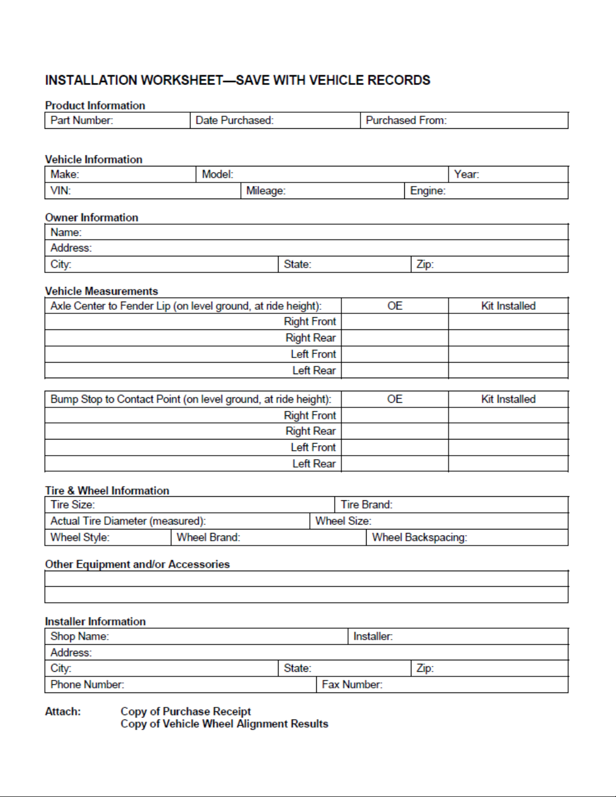
IMPORTANT! To validate the warranty on this purchase please be sure to mail in the warranty card.
Claims not covered under warranty-
• Parts subject to normal wear; this includes bushings, bump stops, ball joints, tie rod ends and heim joints
• Discontinued products at Trail Master Suspension’s
discretion
• Bent or dented product
• Finish after 90 days
• Leaf or coil springs used without proper bump stops
• Products with evident damage caused by abrasion or contact with other items
• Damage caused as a result of not following recommendations or requirements called out in the installation manuals
• Products used in applications other than listed in Trail Master Suspension’s
catalog
• Components or accessories used in conjunction with other manufacturer’s systems
• Warranty claims without “Proof of Purchase”
• Trail Master Suspension
accepts no responsibility for any altered product, improper installation, lack of
or improper maintenance, or improper use of our products.
E-Mail: info@trailmastersuspension.com
Website: www.trailmastersuspension.com
Ph: (877) 695-7812
22
 Loading...