

Page 1
TM411N, TM412N,
TM413N, TM414N
Revised
7.11.13
400 W. Artesia Blvd. Fax: (310) 747-3912
Compton, CA 90220 Ph: (877) 695-7812
www.trailmastersuspension.com
FORD SUPER DUTY F-250 4WD GAS SUSPENSION LIFT KIT
2011– 2013 KIT# TM412N
FORD SUPER DUTY F-350 4WD GAS SUSPENSION LIFT KIT
2011– 2013 KIT# TM414N
FORD SUPER DUTY F-250 4WD DIESEL SUSPENSION LIFT KIT
2011– 2013 KIT# TM411N
FORD SUPER DUTY F-350 4WD DIESEL SUSPENSION LIFT KIT
2011– 2013 KIT# TM413N
WARNING
Installation of a Trail Master suspension lift kit will change the
vehicle’s center of gravity and handling characteristics both onand off-road. You must drive the vehicle safely! Extreme care
must be taken to prevent vehicle rollover or loss of control, which
could result in serious injury or death. Avoid sudden shar p turns
or abrupt maneuvers and always make sure all vehicle occupants
have their seat belts fastened.
WARNING
Before you install this kit, read and understand all instructions,
warnings, cautions, and notes in this instruction sheet and in the
vehicle owner’s manual.
CAUTION
Proper installation of this kit requires knowledge of the factory
recommended procedures for removal and installation of original
equipment components. We recommend that the factory shop
manual and any special tools needed to service your vehicle be
on hand during the installation. Installation of this kit without
proper knowledge of the factory recommended procedures may
affect the performance of these components and the safety of the
vehicle. We strongly recommend that a certified mechanic familiar
with the installation of similar components install this kit.
WARNING
This kit should only be installed on a vehicle that is in good working condition. Before you install the kit, thoroughly inspect the
vehicle for corrosion or deformation of the sheet metal. If the vehicle is suspected to have been in a collision or misused, do not
install this kit. Off-road use of your vehicle with this kit installed
may increase the stress applied to the factory components. Failure to observe this warning may result in serious personal injury
and/or severe damage to your vehicle.
WARNING
Many states and municipalities have laws restricting bumper
heights and vehicle lifts. Consult state and local la ws to determine
if the changes you intend to make to the vehicle comply with the
law.
WARNING
The installation of larger tires may reduce the effectiveness of the
braking system.
WARNING
Always wear eye protection when operating power tools.
WARNING
Before you install this kit, block the vehicle tires to prevent the
vehicle from rolling.
WARNING
DO NOT combine suspension, body, or other lift devices. Use of
vehicle with combined lifts may result in unsafe and/or une xpected
handling characteristics.
NOTE
Lift height may vary depending on vehicle configuration, engine
size, additional accessories, the factory suspension package, and
vehicle’s condition.
NOTE
Trail Master recommends using thread locking compound on the
1
threads of all kit nuts and bolts unless specified otherwise in thes e
instructions.
Page 2
TM411N, TM412N,
TM413N, TM414N
Revised
7.11.13
2
Page 3

Before Starting Installation
TM411N, TM412N,
TM413N, TM414N
Revised
7.11.13
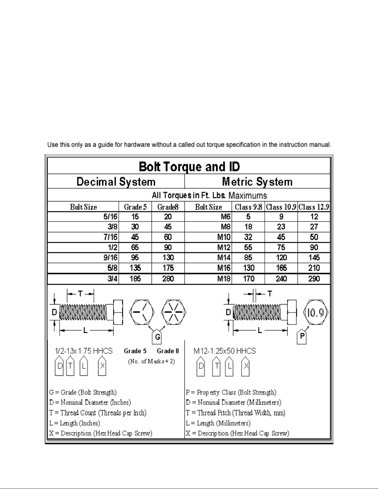
Torque Specifications:
NOTE
Kit parts are prefaced by the word kit and appear in
bold print.
1. Carefully read all warnings and instructions completely before beginning.
2. Verify all parts have been received in this kit by
checking the parts list at the end of this document.
3. Only install this kit on the vehicle for which it is
specified. If anytime during the installation you encounter something different from what is outlined in
the instructions, call technical support at (877) 695-
7812.
4. Park vehicle on a clean, dry, flat, level surface and
block tires so vehicle cannot roll in either direction.
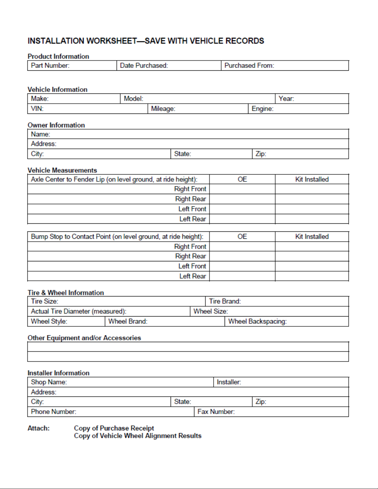
5. Measure ride height with the vehicle supporting its
own weight on level ground. To settle the suspension,
the vehicle should be driven forward at least 10 feet
immediately prior to taking these measurements. Ride
height is the measurement from the center of the axle
straight up (vertical) to the fender lip. Record this
measurement for all four wheels.
NOTE
Adhere to recommendations when replacement fasteners, retainers and keepers are called out in the
factory service manual. When re-assembling the vehicle it is recommended by the vehicle manufacturer
that certain fasteners are replaced in order to maintain proper retention characteristics. This system
may not include all replacement hardware as recommended by the factory service manual. Additional
replacement hardware should be obtained prior to
installation of this system to meet the requirements
of the factory service manual.
Engine Compartment
1. Disconnect both battery cables. Disconnect
negative cable first, then positive cable.
Wheel & Tire Requirements
The factory wheel and tire combination will fit
once this kit is installed.
Tire & Wheel Information:
Due to differences in manufacturing, dimensions and
inflated measurements, tire and wheel combinations
should be test fit prior to installation. Tire and wheel
choice is crucial in assuring proper fit, performance,
and the safety of your Trailmaster equipped vehicle.
For this application, we recommend a wheel not to
exceed 10” in width with a maximum backspacing of
5 3/4” must be used. Additionally, a quality tire of
radial design, not exceeding 37” tall X 12.50” wide is
also recommended. Violation of these recommendations will not be endorsed as acceptable by Trailmaster Suspension and will void any and all warranties
either written or implied.
See factory service manual for torque values
when reusing OE fasteners.
See factory service manual for torque values when re-using
OE fasteners.
Bolt Size Grade 5 (ft.-lbs.) Grade 8 (ft.-lbs.)
1/4”-20 10 10
1/4”-28 10 12.5
5/16”-18 17 22.5
5/16”-24 20 25
3/8”-16 30 40
3/8”-24 35 45
7/16”-14 50 65
7/16”-20 55 70
1/2”-13 75 100
1/2”-20 80 115
9/16”-12 105 135
9/16”-18 115 150
5/8”-11 150 195
5/8”-18 160 210
3/4”-16 175 225
3
Page 4

Front Installation:
1. Position your vehicle on a smooth, flat, hard
surface (i.e. concrete or asphalt). Block the
rear tires and set the emergency brake.
2. Measure and record the distance from the
center of each wheel to the top of its fender
opening. Record below.
3. Place the vehicle in neutral. Place your floor
RF: LF:
TM411N, TM412N,
TM413N, TM414N
Revised
7.11.13
IMPORTANT!: THE ENTIRE INSTALLA-
TION PROCESS MUST BE DONE WITH
HAND TOOLS TO ENSURE PROPER IN-
STALLATION. DO NOT USE IMPACT
TOOLS.
11. Install new pitman arm on sector shaft. Oil
the sector shaft threads to ensure a proper
torque reading. Install Pitman arm retaining
nut and tighten until snug. See Illustration
1.
LR: RR:
jack under the front axle and raise the vehicle. Place jack stands under the frame rails
and lower the frame onto the stands. Remove the jack and place the vehicle back in
gear, set the emergency brake, and place
blocks both in front and behind the rear
wheels.
4. Remove the track bar bolt from the driver
side frame mount. Save this hardware for
re-use.
5. Remove the cast track bar mount on driver
side of frame. Save the bolts and pal nuts.
Hardware will be reused.
6. Unbolt the sway bar from the sway bar end
links on both sides of the vehicle. Save the
hardware for reuse.
7. Mark the orientation of the sway bar and
unbolt it from the frame of the vehicle. Save
the hardware for reuse.
8. If the vehicle is equipped with a factory
steering stabilizer unbolt it and remove it
from the vehicle.
9. Remove the cotter pin and nut from drag
link, at the pitman arm. Save the nut for
reinstallation. Use a tie rod separator to
separate drag link from Pitman arm.
12. Insert the key and unlock the steering wheel.
13. Install the Pitman arm torque tool (96-5002)
to the Pitman arm using one of the previously removed OE 14mm track bar bracket
outer retaining bolt and nut plate. See Illus-
tration 2.
14. Secure the torque tool (96-5002) to the exist-
ing hole in the frame crossmember using the
supplied 7/16” X 1 1/4” bolt and hardware.
See Illustration 2.
NOTE: The steering wheel may need to
be turned in order for the hole in the torque
tool and the frame crossmember to line up.
Once the bolts are tightened the torque tool
will align it’s self properly.
NOTE: The use of the torque tool is to
keep the Pitman arm from moving right or
Illustration 1
Pitman Arm Assembly
Sector
Shaft
Nut
Cotter
Pin
10. Remove the sector Pitman arm retaining nut
and save for reinstallation. Use a Pitman
arm puller to remove the OE pitman arm.
The threads of the sector shaft and the Pitman arm retaining nut must be cleaned of all
factory dry adhesive.
FD-800
Pitman
Drag
Link
4
Arm
Page 5

Frame Crossmember
OE 14mm Track
Bar Retaining Bolt
Existing
Hole
Illustration 2
Pitman Arm Torque Tool
Pitman
Arm
TM411N, TM412N,
TM413N, TM414N
Revised
7.11.13
96-5002
Torque Tool
Pitman
Arm
Frame
Crossmember
96-5002 Torque Tool
left, but allow for movement up the sector
shaft. If you do not have this tool, a length
of chain or a flat bar with two holes is a
suitable replacement.
15. Torque the Pitman arm retaining nut to 375
ft./lbs.
16. With the torque tool (96-5002) still in place
remove the pitman arm retaining nut. The
threads of the sector shaft and the Pitman
arm retaining nut MUST
be cleaned using
brake cleaner or another suitable method to
remove the previously applied oil.
Illustration 3
Track Bar Bracket Assembly
OE 14mm
Nut Plate
7/16” X 1
1/4” Bolt
17. Use the entire supplied thread locking compound to thoroughly cover the entire surface
of the threads on the Pitman arm retaining
nut.
18. Reinstall the Pitman arm retaining nut to the
sector shaft and torque to 350 ft./lbs.
NOTE: Whether re-using the existing
pitman arm retaining nut or replacing with
a new nut, the supplied locking compound
must be used.
19. Unbolt and remove the Pitman arm torque
tool (96-5002) from the vehicle.
OE Pal
Nut
(1) 9/16” X
1 1/2” Gr. 8
Bolts
9/16”
Hardware
OE Track Bar Hardware
82-9290 Track
Bar Drop
Bracket
OE Bolt
Track Bar
(2) 9/16”
X 3” Gr. 8
Bolts
OE Bolt
5
OE Track
Bar Bolt
90-9295
Cam Plates
Page 6
TM411N, TM412N,
TM413N, TM414N
Revised
7.11.13
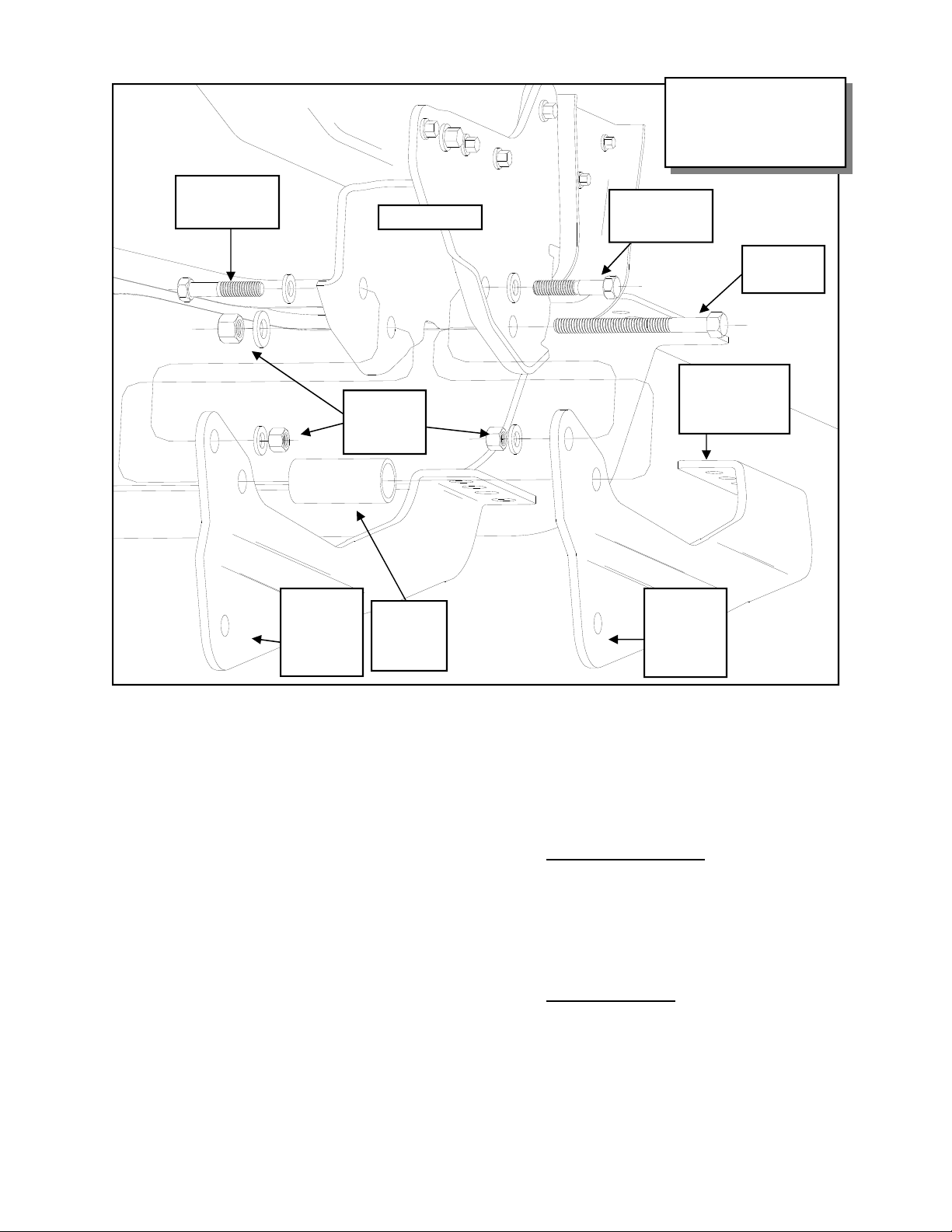
Illustration 4
Front Radius Arm Drop
Bracket Assembly
3/4” X 1 1/2”
Gr. 8 Bolt
82-3166
Radius
Arm Drop
Bracket
Frame Pocket
3/4” Stover
Nut and
Washers
90-2507
Spacer
Tube
3/4” X 1 1/2”
Gr. 8 Bolt
3/4” X 5”
Gr. 8 Bolt
The Notched
Bracket Goes
on the Bottom
82-3167
Radius
Arm Drop
Bracket
NOTE: Save this Pitman arm torque
tool to add to your toolbox for any future Pitman arm installations.
20. Install track bar drop bracket (82-9290) us-
ing (2) 9/16” X 3”, (1) 9/16” X 1 1/2” and
(2) OE bolts. Use thread locker on the bolts.
Torque OE the bolts to 129 ft. lbs. and the
9/16” bolts to 110 ft. lbs. See ILLUSTRATION 3.
21. Unbolt the front brake line bracket from the
lower spring perch. Save hardware for reuse.
22. Unbolt and unclip the ABS wiring connected to the radius arm. Save hardware for
reuse.
23. On the driver side, unclip the axle vent line
from inside the frame.
24. On the passenger side unclip the axle hub
vacuum line from inside of the axle bump
stop plate.
25. Remove the transfer case skid plate. Also
remove the rubber grommets, sleeves and
clips from the frame.
NOTE: Trimming of the transfer case
skid plate is necessary for reinstallation.
On the passenger side
, use the supplied
transfer case skid plate cut template
(52802B-Supplement) as a guide. Line up
the holes and trace the template onto the
skid plate. carefully trim the skid plate.
This modification is needed to clear the
catalytic converter .
On the driver side
, carefully trim off
the rounded kick out in the side of the skid
plate. These modification is needed to
clear the transfer case. These are only
starting points and additional trimming
may be necessary.
6
Page 7

Drill Out (2)
Center Holes
Using Assembled Drop
Bracket as a
7/16”
Drill
Bit
Transfer Case
Skid Plate
TM411N, TM412N,
TM413N, TM414N
Revised
7.11.13
Illustration 5
Front Radius Arm Drop
Drill Picture
7/16” Hardware
Transfer Case
Skid Plate
3/4” X 5”
Gr. 8 Bolt
Front of Vehicle
Illustration 6
Factory Radius Arm Install
3/4” X 1 1/2”
Gr. 8 Bolt
7/16” X 1 1/2”
Bolts (4)
Radius
Arm Drop
Bracket
Assembly
3/4” Hardware
3/4”
X 1
1/2”
Gr. 8
Bolt
Radius
Arm Drop
Bracket
Assembly
OE Bolt
Factory
Radius Arm
OE Nut
7
Page 8

TM411N, TM412N,
TM413N, TM414N
Revised
7.11.13
Before After
OE Bolt
OE Brake
Line Bracket
OE Brake
Line
Illustration 7
Brake Line Drop Install
OE Bolt
Brake Line Drop
Bracket 90-7722
drvr and 907723 pass
Brake Line
Retaining Clip
OE Hard
Line Ferrule
Brake Line
Retaining Clip
Bottom of Vehicle
26. Place a jack under the pinion or radius arm.
On both sides remove the rear bolts holding
the radius arms to the frame of the vehicle.
27. Carefully rotate both radius arms down to
provide adequate space to install the new
drop brackets.
28. On both sides of the vehicle, assemble the
radius arm drop side plates (82-3166 on top)
and (82-3167, with the notch in it, on the
bottom) and bolt radius arm drop to the
Illustration 8
Bump Stop Drop
Assembly
Existing
Bump
Stop
Hole
Drill Out
To 7/16”
Drill Out
Mounting Cup
Hole To
7/16”
7/16” Bolt and
Washer
82-2511 Bump
Stop Drop
Factory
Mounting
Cup
7/16”
Washer
7/16” X 6 1/2”
Bolt
Factory
Bump
Stop
OE Brake
Line
frame. Use the supplied 3/4” X 1 1/2” bolts
in the front hole with the heads of the bolts
facing out. Do not torque at this time. See
ILLUSTRATION 4.
29. Use the spacer tube (90-2507) and the 3/4”
X 5” bolt in the rear hole. Do not torque at
this time. See ILLUSTRATION 4.
30. From the rear, slide the previously removed
and modified OE transfer case skid plate or
the new transfer case skid plate (91-7057) in
between the frame and the rear of the radius
arm drop bracket. Insert (2) 7/16” X 1 1/2”
bolts through the outside holes in the rear of
the drop bracket. Tighten these bolts and
use the radius arm bracket holes as a drill
template to drill out the (2) inside holes in
the factory skid plate and frame. Drill the
holes using a 7/16” drill bit. Insert the remaining (2) 7/16” X 1 1/2” bolts in the
newly drilled holes. See ILLUSTRATION
5.
31. Raise the factory radius arm into the lower
hole in the drop bracket and skid plate. Secure using the OE bolt. Do not tighten this
bolt until vehicle is on the ground. See ILLUSTRATION 6.
32. Torque the 7/16” radius arm drop bracket
hardware to 60 ft. lbs. and the 3/4” hardware
to 200 ft. lbs.
33. Raise the front axle enough to relieve tension on the shock hardware and remove the
shocks from the vehicle.
34. Lower the front axle enough to remove the
coil springs from the front spring pockets.
8
Page 9

Save the factory isolators for re-use.
NOTE: Be sure to support the axle
while the springs and shocks are removed.
35. Remove the front brake line retaining clip.
Separate the brake line from the bracket.
Save the OE clip for reinstallation. See ILLUSTRATION 7.
36. Loosen the OE hard line ferrule, just
enough, to be able to rotate it 180 degrees so
the rubber line is facing toward the bottom
of the vehicle and retighten. See ILLUSTRATION 7.
37. Unbolt and remove the OE brake line
bracket from the frame. Save the OE bolt
for reinstallation.
38. Install the new brake line drop bracket (90-
7722 Drvr and 90-7723 Pass) to the original
hole in the frame rail using the previously
removed OE bolt. See ILLUSTRATION 7.
39. Secure the brake line to the new bracket using the previously removed OE clip. See
ILLUSTRATION 7.
40. Remove the factory front bump stop from
TM411N, TM412N,
TM413N, TM414N
Revised
7.11.13
the bump stop mounting cup. Pliers and a
back and forth rocking motion will assist in
removal of the bump stop.
41. On the driver side, unbolt the bump stop
mounting cup and drill out the factory hole
in the frame and bump stop mounting cup to
7/16”.
42. On the passenger side, unbolt the bump stop
mounting cup. Measure in toward the engine 5/8” from the center of the factory
bump stop hole in the frame. Center punch
and drill and the new hole 7/16” in the
frame. Drill out the bump stop mounting
cup to 7/16”.
43. Use the supplied 7/16” X 6 1/2” bolt and
hardware to bolt the bump stop drop (91-
2511) and mounting cup to the bump stop
hole in frame. See ILLUSTRATION 8.
NOTE: Be sure to fit the tab from the
mounting cup into the hole in the drop.
44. Reinstall the previously removed factory
bump stop into the mounting cup on the new
bump stop drop. See ILLUSTRATION 8.
Illustration 9
Sway Bar Install
OE Sway
Bar End
Link
Steering
Stabilizer
Steering Stabilizer
Mounting Bracket
82-3823
7/16” X 1
3/4” Bolt
OE Nut
12mm X
65mm
Bolt
OE Sway
Bar End
Link
Sway Bar
Drop
Bracket
82-7026
drvr
Sway Bar
OE Studs
Sway Bar Drop
Bracket 82-7029 pass
OE Nut
OE Studs OE Nut
OE Nut
Sway Bar
Spacer Plate
82-3822
7/16” X 1
3/4” Bolt
Front of Vehicle
9
Page 10

45. Using the factory isolators install the sup-
plied front coil springs (24514 Gas or 24515
Diesel) into the spring buckets and raise the
axle into place. Make sure the coil spring
seats properly on the lower spring perch.
46. Install the new shocks (TM7588 0W).
Torque the upper mounting hardware to 46
ft. lbs. and the lower mounting hardware to
111 ft. lbs. Use thread locker on these bolts.
47. Install draglink end into pitman arm and
torque draglink nut to 148 ft. lbs. Reinstall
cotter pin.
48. Install the sway bar drops (82-7026 drvr
and 82-7029 pass) to the OE sway bar
mounting studs on the frame using the previously removed OE hardware. See ILLUSTRATION 9.
49. Carefully raise the sway bar back into place
and on the passenger side insert the steering
stabilizer bracket (82-3823) under the passenger side sway bar mount. On the driver
side insert the sway bar spacer plate (82-
3822) under the driver side sway bar mount.
Secure the supplied 7/16” X 1 3/4” bolts and
hardware. See ILLUSTRATION 9.
NOTE: Be sure the steering stabilizer
mounting hole in the stabilizer bracket is
oriented toward the rear of the vehicle.
50. Reattach the sway bar to the OE sway bar
end links using the previously removed OE
hardware.
51. Install the OE steering stabilizer to the new
steering stabilizer bracket (91-3823) using
the provided 12mm X 65mm bolt and hardware. See ILLUSTRATION 9.
52. Torque all sway bar hardware according to
manufacturers specifications.
53. On the driver side, re clip the axle vent line
on the frame providing adequate slack for
the line at full droop.
54. On the passenger side, reposition the clip on
the axle hub vacuum line to provide adequate slack to re-clip the line to the existing
hole on the outside of the bump stop plate.
NOTE: Be sure that the newly rerouted
vent line does not interfere with the travel of
the bump stop.
TM411N, TM412N,
TM413N, TM414N
Revised
7.11.13
55. Remove the ABS line from the inner fender.
Drill a new hole, using a 15/64” bit, 3”
lower in the fender to provide adequate slack
for line and reattach the ABS line.
56. Reinstall the ABS wiring onto the radius
arms using the factory clips.
57. Refasten the lower brake line mount to the
lower coil spring perch using the OE hard-
ware.
58. Reinstall the front wheels and lower the vehicle to the ground. Torque to manufacturers specs.
59. Torque the OE rear Radius arm bolts to 222
ft. lbs.
60. Reinstall the track bar into the Trailmaster
track bar bracket (82-9290) using the OE
bolt and adjustable cam plates (90-9295).
Torque to 406 ft. lbs. See ILLUSTRATION
3.
NOTE: You may find that having
someone inside the vehicle and moving the
steering wheel from side to side will aid in the
alignment of the track bar. DO NOT
start the
engine for this! You only have to move it
enough to line the holes up on the track bar
mount.
61. On both sides of the vehicle, check the
routing of the brake lines and the ABS wire
harnesses. There must be no pinching,
rubbing, or stretching of either component.
At full droop, cycle the steering from lock to
lock while observing the reaction of these
components. Reposition them if needed.
62. With the vehicle fully on the ground, meas-
ure the clearance between each
tire and inner fender. If the axle is not properly centered, readjust the track bar cam hardware.
Torque to 406 ft.
NOTES:
On completion of the installation, have
the suspension and headlights re-aligned.
After 100 miles recheck for proper torque
on all newly installed hardware.
Recheck all hardware for tightness after
off road use.
10
Page 11

Rear Installation:
1. Block the front tires and raise the rear of the
vehicle. Support the frame with jack stands
forward of the rear springs.
2. Remove the wheels and tires.
3. Unscrew the rear axle vent tube to separate
the rear brake line bracket from the rear axle.
4. Remove the shocks on both sides of the vehicle. It may be necessary that you slightly
raise the axle to unload the shocks for removal.
5. On the driver side, unbolt the emergency
brake line bracket from the upper spring
plate. Save hardware for reuse.
6. If your vehicle is equipped with factory
sway bar, unbolt it from the end links. Unbolt and remove the end links from the vehicle.
7. Support the rear axle with a floor jack and
remove the U-bolts on the driver side.
Slightly loosen the U-bolts on the passenger
side.
8. Lower the rear axle and remove the factory
block.
NOTE: Be sure not to over extend the
rear brake line and rear axle vent line.
9. While supporting the rear leaf spring, remove
the factory spring mounting bolts and remove
the leaf spring from the driver side only at
this time.
TM411N, TM412N,
TM413N, TM414N
Revised
7.11.13
NOTE: DO NOT
bolt on the driver side. The extra threads
will be needed to attach the OE emergency
brake line bracket.
trim the excess center
APPLICATIONS:
1. FOR F-250 MODELS, INSTALL
THE ADD-A-LEAVES (13150-1 AND
13150-2) AND LIFT BLOCK 95407SD DRVR AND 95-406SD PASS.
2. FOR F-350 MODELS, INSTALL
THE ADD-A-LEAVES (13150-1 AND
13150-2) AND LIFT BLOCKS 95556SD DRVR AND 95-557SD PASS.
12. Install the supplied lift block (F-250:
407SD drvr and 95-406SD pass
556SD drvr and 95-557SD pass)
application. See the side note for proper applications. Make sure the pin fits into the
hole on the spring perch. Use your floor jack
to raise the axle to the spring making sure the
pin on the factory leaf spring assembly fits
into the hole on the lift block. Secure the
assembly with the 5/8” U-bolts (F-250: 13-
90540 or F-350 13-90560 ) 5/8” hi-nuts (PN
20-65471) and washers supplied. Do not
torque the hi-nuts at this time. See ILLUSTRATION 10.
) or (F-350: 95-
95-
depending on
10. Disassemble leaf spring and insert the add-a-
leaves (13150-1 and 13150-2).
NOTE: The add-a-leaves will be added
onto the bottom of the factory spring pack, progressively according to length. Do not install
the add-a-leaves below the factory overload
spring if the vehicle is equipped with one. See
ILLUSTRATION 10.
11. Using the C-clamps, bolt the leaf pack back
together using the supplied center bolt with
the head of the bolts facing down and the nut
on the top. Reinstall the spring pack to the
hangers using the OE hardware. Do not
torque at this time.
NOTE: Make sure the block sits flush
on the axle perch.
13. Repeat the installation on the other side of
the vehicle.
14. On driver side, carefully bend down the
emergency brake line bracket that secures the
line to the frame and bolt the emergency
brake line bracket back to the spring pack
center bolt using the supplied 10mm-1.5 nut.
15. Install your new Trailmaster shocks
(TM75790W). Torque the upper mounting
hardware to 46 ft. lbs. and the lower mounting hardware to 66 ft. lbs. Use thread locker
on these bolts.
11
Page 12

Illustration 10
Rear Spring With Add-A-Leaf
Assembly
Front of Vehicle
Add-A-Leaf
(13150-1)
F-250:13-90540 U-bolts
F-350
: 13-90560 U-bolts
10mm-1.5
Nut
Upper
Spring Plate
Factory Overload Spring
And plate, F-350 only.
TM411N, TM412N,
TM413N, TM414N
Revised
7.11.13
Add-A-Leaf
(13150-2)
Factory Overload
Spring
if Equipped
Supplied Center Bolt
97-716 or 97-165
F-250 models: 95-407SD
drvr and 95-406SD pass Lift
Block
F-350 models
drvr and 95-557SD pass
The goal of the offset rear
block is to shift the axle forward to center the wheel.
5/8” Hi-Nuts
: use 95-556SD
OE Brake
Line Mount
Brake
Line
3/8” X
1” Bolt
Rear Axle
NOTE: Install the (13150-1 and
13150-2) add-a leaves onto the
bottom of the factory spring
pack. Do not install below the
factory overload spring if the
vehicle is equipped with one.
90-7031
Brake
Line
Mount
Add-A-Leaf Rear Spacer Options:
1. F-250: Add-a-leaves (13150-1 and 13150-2) and lift block 95-407SD drvr and 95406SD pass.
2. F-350: Add-a-leaves (13150-1 and 13150-2) and lift blocks 95-556SD drvr and 95557SD pass.
See Inset box after step 11, page 11.
12
12
Page 13

15. Remove the (2) bolts that secure the center
drive shaft bearing. Lower bearing and install
1/4” of shim thickness for each inch of rear
lift. Use new 7/16” X 2 1/4” bolts and torque
to 55 ft./lbs.
NOTE: 1/4” of shim for each inch of
lift is only a starting point. Only by driving the
vehicle and adding or removing shims can the
high speed vibration be totally eliminated. The
off the line vibration is caused by axle wrap up
and cannot be eliminated with these products.
16. If vehicle came equipped with a rear sway
bar, assemble the rear sway bar end links
(82-2446) using the bushings (45359) and
sleeves (60859H).
17. Secure the new rear sway bar end links (82-
2446) to the frame and the sway bar using the
provided 12mm-1.75 X 70mm. Torque the
bolts according to the torque chart on page
19.
18. Secure the new rear brake line bracket (90-
7031) to the rear axle by reinstalling the vent
tube.
19. Secure the OE brake line bracket to the new
brake line bracket (90-7031) using the supplied 3/8” X 1” bolt and hardware.
20. Reinstall the wheels and tires and lower the
vehicle to the ground. Torque lug nuts to
manufacturer specification.
TM411N, TM412N,
TM413N, TM414N
Revised
7.11.13
21. Torque the spring mounts at this time. The
front bolts are torqued to 250 ft. lbs. and the
rear bolts are torqued to 185 ft. lbs. Torque
the 5/8” U-bolts to 120 ft. lbs.
22. Re-check the wheel lug torque on all four
wheels at this time.
23. Re-check all
hardware (both the front and the
rear) for proper installation and torque!!
24. If you wish, you may trim the excess u-bolt
thread length. If you do this you should
leave approximately one inch of thread exposed after the U-bolts are torqued.
25. On both sides of the vehicle, check the
routing of the brake lines and the ABS wire
harnesses. There must be no pinching,
rubbing, or stretching of either component.
Reposition them if needed.
NOTES:
On completion of the installation, have the
suspension and headlights re-aligned.
After 100 miles recheck for proper torque
on all newly installed hardware.
Recheck all hardware for tightness after
off road use.
13
Page 14

Dynamic Vehicle Check
TM411N, TM412N,
TM413N, TM414N
Revised
7.11.13
NOTES:
1. Check steering and suspension in all positions
to ensure that there is no bind and adequate
clearance between all moving, fixed, and heated
members. Check operation of clutch, brake system, and parking brake. Check operation of transmission and transfer case. Ensure there is full engagement in all gears and 4WD ranges. Check
battery connections and electrical component operations. Test-drive vehicle.
WARNING
Re-torque all fasteners after 500 miles and after
off road use. All suspension lift components
should be visually inspected and fasteners retorqued during routine vehicle servicing.
Caution:
Larger wheel and tire combinations increase
stress and wear on steering and suspension
components, which leads to increased maintenance and higher risk for component failure. Larger wheel and tire combinations also alter speedometer calibration, braking effectiveness, center
of gravity, and handling characteristics. Consult
an experienced local off road shop to find what
wheel and tire combinations work best with your
vehicle.
On completion of the installation, have the
suspension and headlights re-aligned.
After 100 miles recheck for proper torque
on all newly installed hardware.
Recheck all hardware for tightness after
off road use.
IMPORTANT!: 18” OR LARGER WHEELS
MUST BE USED IN
CONJUNCTION WITH THIS LIFT KIT!
NOTE
All warranty information, instruction sheets, and
other documents regarding the installation of this
product must be retained by the vehicle owner
Information contained in the instructions and on
the warranty card will be required for any warranty claims. The vehicle owner needs to understand the modifications made to the vehicle and
how they affect vehicle handling and performance. Failure to provide the customer with this
information can result in damage to the vehicle
and severe personal injury.
.
14
Page 15

TM411N, TM412N,
TM413N, TM414N
Revised
7.11.13
Part # Description Qty.
Kit Parts List:
Box TM411N-1
82-7026 SWAY BAR DROP:
82-7029 SWAY BAR DROP:
82-3822 SWAY BAR SPACER 1
82-3823 STEERING STABILIZER BRACKET 1
90-6315 HARDWARE PACK:
70-0431751800 7/16” X 1 3/4” GR. 8 HEX BOLT 4
73-04300034 7/16” HARDENED FLAT WASHER 8
72-04300100816 7/16” GR. 8 STOVER NUT 4
90-6803 HARDWARE PACK:
70-0120651758800 12mm– 1.75 X 65mm 10.9 HEX BOLT 1
73-01217508812 12mm FLAT WASHER 2
72-01200832 12mm– 1.75 STOVER NUT 1
82-9290 TRACK BAR DROP BRACKET 1
90-6772 HARDWARE PACK:
56C300HCS8Y 9/16” X 3” HEX BOLT GR. 8 2
56C150HCS8Y 9/16” X 1 1/2" HEX BOLT GR. 8 1
56CNUCZ 9/16” STOVER NUT GR. C 3
56NWHDY/SAE 9/16” HARDENED FLAT WASHER 6
FD-800-1 PITMAN ARM 1
82-2511 BUMP STOP SPACER 2
90-6390 HARDWARE PACK:
70-0436501800 7/16” X 6 1/2” USS GR. 8 HEX BOLT 2
73-04300034 7/16” SAE FLAT WASHER 4
72-04300100816 7/16” USS GR.8 STOVER NUT 2
90-6042 HARDWARE PACK:Rear Sway Bar Links 1
45359 5/8” RUBBER HOURGLASS BUSHING 4
60859H 5/8” O.D. X 12mm I.D. X 1.480” SLEEVE 4
90-6572 HARDWARE PACK:Rear Sway Bar Links 1
.120C750HCS1Z 12mm-1.75 X 70mm HEX BOLT GR. 10. 9 4
.120CNNEZ 12mm-1.75 NYLOC K NUT 4
.120NWHDY 12mm HARDENED FLAT WASHER 8
82-2446 REAR SWAY BAR END LINKS 2
96-5002 PITMAN ARM TOOL 1
Drvr 1
Pass 1
Sway Bar Drop 1
Steering Stabilizer 1
Track Bar Drop 1
Bump Stop 1
15
Page 16

TM411N, TM412N,
TM413N, TM414N
Revised
7.11.13
Part # Description Qty.
90-6595 HARDWARE PACK: Pitman Arm Tool 1
THREAD LOCKER 1
0431251800 7/16" X 1 1/4" GR. 8 HEX BOLT 1
04300030 7/16" FLAT WASHER 1
04300100512 7/16" NYLOC NUT 2
90-7031 BRAKE LINE MOUNT:
Rear 1
90-6773 HARDWARE PACK:
Brake Line Mount 1
0431251800 3/8” X 1” HEX BOLT GR. 8 1
04300100512 3/8” NYLOCK NUT GR. 5 1
3/8” HARDENED FLAT WASHER 2
72-01015008812 10MM X 1.5 PITCH NYLOCK:
Rear E-Brake Bracket 1
90-7722 FRONT BRAKE LINE DROP BRACKET:
Drvr 1
90-7723 FRONT BRAKE LINE DROP BRACKET:
Pass 1
90-6918 HARDWARE PACK:
Cam Plates 1
90-9295 Cam Plate 2
Box TM411N-2
90-6386 HARDWARE PACK:
Radius Arm 1
90-2507 RADIUS ARM SPACER TUBE 2
82-3166 RADIUS ARM DROP SIDE PLATE 2
82-3167 RADIUS ARM DROP SIDE PLATE
(With Notch) 2
90-6370 HARDWARE PACK:
Radius Arm Drop 1
70-0751501800 3/4” X 1 1/2” HEX BOLTS GR. 8 4
72-075100816 3/4” STOVER NUTS 6
73-07500830 3/4” WASHERS SAE GR. 8 12
70-0755001800 3/4” X 5 HEX BOLTS GR. 8 2
70-0431501800 7/16” X 1 1/2” HEX BOLTS GR.8 8
72-043100816 7/16” STOVER NUTS 8
73-04300830 7/16” WASHERS SAE GR. 8
16
90-1080 3/8” Driveline Shim 2
90-1081 1/4” Driveline Shim 2
90-1082 1/8” Driveline Shim 2
90-6013 HARDWARE PACK:
70-04300100816 7/16” x 2 1/4” USS Grade 8 Bolt 2
73-04300042 7/16 USS Hardened Washer 2
Box TM411N-3
TM75880W FRONT SHOCKS 2
TM75790W REAR SHOCKS 2
Driveline Shim 1
16
Page 17

TM411N, TM412N,
TM413N, TM414N
Revised
7.11.13
Part # Description Qty.
Box TM411N-4
13150-1 ADD-A-LEAF 2
13150-2 ADD-A-LEAF 2
90-7130 HARDWARE PACK: Add-A-Leaf
98-00300-1 3” SPRING CLAMP 4
98-003002 3” SPRING PLATE 4
97-716 7/16”X 4 1/2” CENTER BOLT 2
8771-1 7/16”GR. 8 CENTER BOLT NUT 2
90-6337 HARDWARE PACK:
Add-A-Leaf 1
97-165 10MM X 165MM CENTER PIN 2
72-01015008812 10MM-1.5 NUT (CENTER BOLT NUT) 2
Box TM411N-5
24514 COILS GASOLINE ENGINE 1
OR Box TM413N-5
24515 COILS DIESEL ENGINE 1
Box TM411N-6: F250 Only
95-407SD 4" REAR LIFT BLOCK:
Drvr: F-250 1
95-406SD 4" REAR LIFT BLOCK:
Pass: F-250 1
13-90540 U-BOLT
: F-250 4
20-65471 HARDWARE PACK:
5/8” Hi nuts & Washers 1
Box TM413N-6: F350 Only
95-556SD 5 1/2” REAR LIFT BLOCK: F-350 1
95-557SD 5 1/2” REAR LIFT BLOCK: F-350 1
13-90560 U-BOLT: F-350 4
20-65471 HARDWARE PACK:
5/8” Hi nuts & Washers 1
17
Page 18

TM411N, TM412N,
TM413N, TM414N
Revised
7.11.13
Revision Page:
18
Page 19
TM411N, TM412N,
TM413N, TM414N
Revised
7.11.13
19
Page 20

TM411N, TM412N,
TM413N, TM414N
Revised
7.11.13
Notice to Owner Operator, Dealer and Installer:
Vehicles that have been enhanced for off-road performance often have unique handling characteristics
due to the higher center of gravity and larger tires. This vehicle may handle, react and stop differently than
many passenger cars or unmodified vehicles, both on and off–road. You must drive your vehicle safely!
Extreme care should always be taken to prevent vehicle rollover or loss of control, which can result in serious injury or even death. Always avoid sudden sharp turns or abrupt maneuvers and allow more time and
distance for braking! Trail Master Suspension
reminds you to fasten your seat belts at all times and reduce speed! We will gladly answer any questions concerning the design, function, maintenance and correct use of our products.
Please make sure your Dealer/Installer explains and delivers all warning notices, warranty forms
and instruction sheets included with Trail Master Suspension
product.
Application listings in this catalog have been carefully fit checked for each model and year denoted. However, Trail Master Suspension
reserves the right to update as necessary, without notice, and will not be
held responsible for misprints, changes or variations made by vehicle manufacturers. Please call when in
question regarding new model year, vehicles not listed by specific body or chassis styles or vehicles not
originally distributed in the USA.
Please note that certain mechanical aspects of any suspension lift product may accelerate ordinary wear of original equipment components. Further, installation of certain Trail Master Suspension
products may void the vehicle’s factory warranty as it pertains to certain covered parts; it is the consumer’s responsibility to check with their local dealer for warranty coverage before installation of the lift.
Warranty and Return policy:
Trail Master Suspension
materials. Trail Master Suspension’s
Trail Master Suspension’s
warranties its full line of products to be free from defects in workmanship and
obligation under this warranty is limited to repair or replacement, at
option, of the defective product. Any and all costs of removal, installation,
freight or incidental or consequential damages are expressly excluded from this warranty. Trail Master
Suspension is not responsible for damages and / or warranty of other vehicle parts related or non-related
to the installation of Trail Master Suspension
product. A consumer who makes the decision to modify his
vehicle with aftermarket components of any kind will assume all risk and responsibility for potential damages incurred as a result of their chosen modifications. Warranty coverage does not include consumer
opinions regarding ride comfort, fitment and design. Warranty claims can be made directly with Trail Mas-
ter Suspension or at any factory authorized Trail Master Suspension dealer.
IMPORTANT! To validate the warranty on this purchase please be sure to mail in the warranty card.
Claims not covered under warranty-
• Parts subject to normal wear; this includes bushings, bump stops, ball joints, tie rod ends and heim joints
• Discontinued products at Trail Master Suspension’s
discretion
• Bent or dented product
• Finish after 90 days
• Leaf or coil springs used without proper bump stops
• Products with evident damage caused by abrasion or contact with other items
• Damage caused as a result of not following recommendations or requirements called out in the installation manuals
• Products used in applications other than listed in Trail Master Suspension’s
catalog
• Components or accessories used in conjunction with other manufacturer’s systems
• Warranty claims without “Proof of Purchase”
• Trail Master Suspension
accepts no responsibility for any altered product, improper installation, lack of
or improper maintenance, or improper use of our products.
E-Mail: info@trailmastersuspension.com
Website: www.trailmastersuspension.com
Ph: (877) 695-7812
20
 Loading...