

Page 1
400 W. Artesia Blvd. Fax: (310) 747-3912
Compton, CA 90220 Ph: (877) 695-7812
www.trailmastersuspension.com
JEEP WRANGLER (TJ) 4” SPRING KIT
‘97- ’06 KIT# TM3440-20013
WARNING
Installation of a Trail Master suspension lift kit will
change the vehicle’s center of gravity and handling
characteristics both on- and off-road. You must drive
the vehicle safely! Extreme care must be taken to
prevent vehicle rollover or loss of control, which
could result in serious injury or death. Avoid sudden
sharp turns or abrupt maneuvers and always make
sure all vehicle occupants have their seat belts fastened.
WARNING
Before you install this kit, read and understand all
instructions, warnings, cautions, and notes in this
instruction sheet and in the vehicle owner’s manual.
CAUTION
Proper installation of this kit requires knowledge of
the factory recommended procedures for removal
and installation of original equipment components.
We recommend that the factory shop manual and
any special tools needed to service your vehicle be
on hand during the installation. Installation of this kit
without proper knowledge of the factory recommended procedures may affect the performance of
these components and the safety of the vehicle. We
strongly recommend that a certified mechanic familiar with the installation of similar components install
this kit.
WARNING
This kit should only be installed on a vehicle that is in
good working condition. Before you install the kit,
thoroughly inspect the vehicle for corrosion or deformation of the sheet metal. If the vehicle is suspected
to have been in a collision or misused, do not install
this kit. Off-road use of your vehicle with this kit installed may increase the stress applied to the factory
components. Failure to observe this warning may
result in serious personal injury and/or severe damage to your vehicle.
WARNING
Many states and municipalities have laws restricting
bumper heights and vehicle lifts. Consult state and
local laws to determine if the changes you intend to
make to the vehicle comply with the law.
WARNING
The installation of larger tires may reduce the effectiveness of the braking system.
WARNING
Always wear eye protection when operating power
tools.
WARNING
Before you install this kit, block the vehicle tires to
prevent the vehicle from rolling.
WARNING
DO NOT combine suspension, body, or other lift devices. Use of vehicle with combined lifts may result
in unsafe and/or unexpected handling characteristics.
NOTE
Lift height may vary depending on vehicle configuration, engine size, additional accessories, the factory
suspension package, and vehicle’s condition.
NOTE
Trail Master recommends using thread locking compound on the threads of all kit nuts and bolts unless
specified otherwise in these instructions.
1
Page 2
2
Page 3

Before Starting Installation
NOTE
Kit parts are prefaced by the word kit and appear in
bold print.
Torque Specifications:
See factory service manual for torque values when
reusing OE fasteners.
1. Carefully read all warnings and instructions
completely before beginning.
2. Verify all parts have been received in this kit by
checking the parts list at the end of this document.
3. Only install this kit on the vehicle for which
it is specified. If anytime during the installation
you encounter something different from what is
outlined in the instructions, call technical support
at (877) 695-7812. Park vehicle on a clean, dry,
flat, level surface and block tires so vehicle cannot roll in either direction.
4. Park vehicle on a clean, dry, flat, level surface
and block tires so vehicle cannot roll in either
direction.
5. Measure ride height with the vehicle supporting
its own weight on level ground. To settle the
suspension, the vehicle should be driven forward at least 10 feet immediately prior to taking
these measurements. Ride height is the measurement from the center of the axle straight up
(vertical) to the fender lip. Record this measurement for all four wheels.
NOTE
Adhere to recommendations when replacement fasteners, retainers and keepers are called out in the factory service manual. When re-assembling the vehicle it
is recommended by the vehicle manufacturer that certain fasteners are replaced in order to maintain proper
retention characteristics. This system may not include
all replacement hardware as recommended by the factory service manual. Additional replacement hardware
should be obtained prior to installation of this system
to meet the requirements of the factory service manual.
See factory service manual for torque values when re-using
OE fasteners.
Bolt Size Grade 5 (ft.-lbs.) Grade 8 (ft.-lbs.)
1/4”-20 10 10
1/4”-28 10 12.5
5/16”-18 17 22.5
5/16”-24 20 25
3/8”-16 30 40
3/8”-24 35 45
7/16”-14 50 65
7/16”-20 55 70
1/2”-13 75 100
1/2”-20 80 115
9/16”-12 105 135
9/16”-18 115 150
5/8”-11 150 195
5/8”-18 160 210
3/4”-16 175 225
Wheel & Tire Requirements
The factory wheel and tire combination will fit once this
kit is installed.
Engine Compartment
1. Disconnect both battery cables. Disconnect
negative cable first, then positive cable.
3
Page 4
Prepare to Install Front
Suspension
WARNING
Compressed coil springs can expand violently causing
serious personal injury. Before removing the coil
springs, lower the axle housing as far as possible to allow the coil springs to expand.
1. Loosen, but do not remove, lug nuts on each
front wheel.
2. Jack the rear of the vehicle with the floor jack
under the differential and place jack stands under the frame just behind the lower control arm
frame mounts. Leave the jack stands high
enough to let the floor jack down and still have
the front tires suspended in the air. Keep the
floor jack under the differential with slight pressure for support. Remove the front wheels.
WARNING
Use extreme caution when lifting vehicle from ground.
To prevent serious personal injury, ensure the lifting device is securely placed.
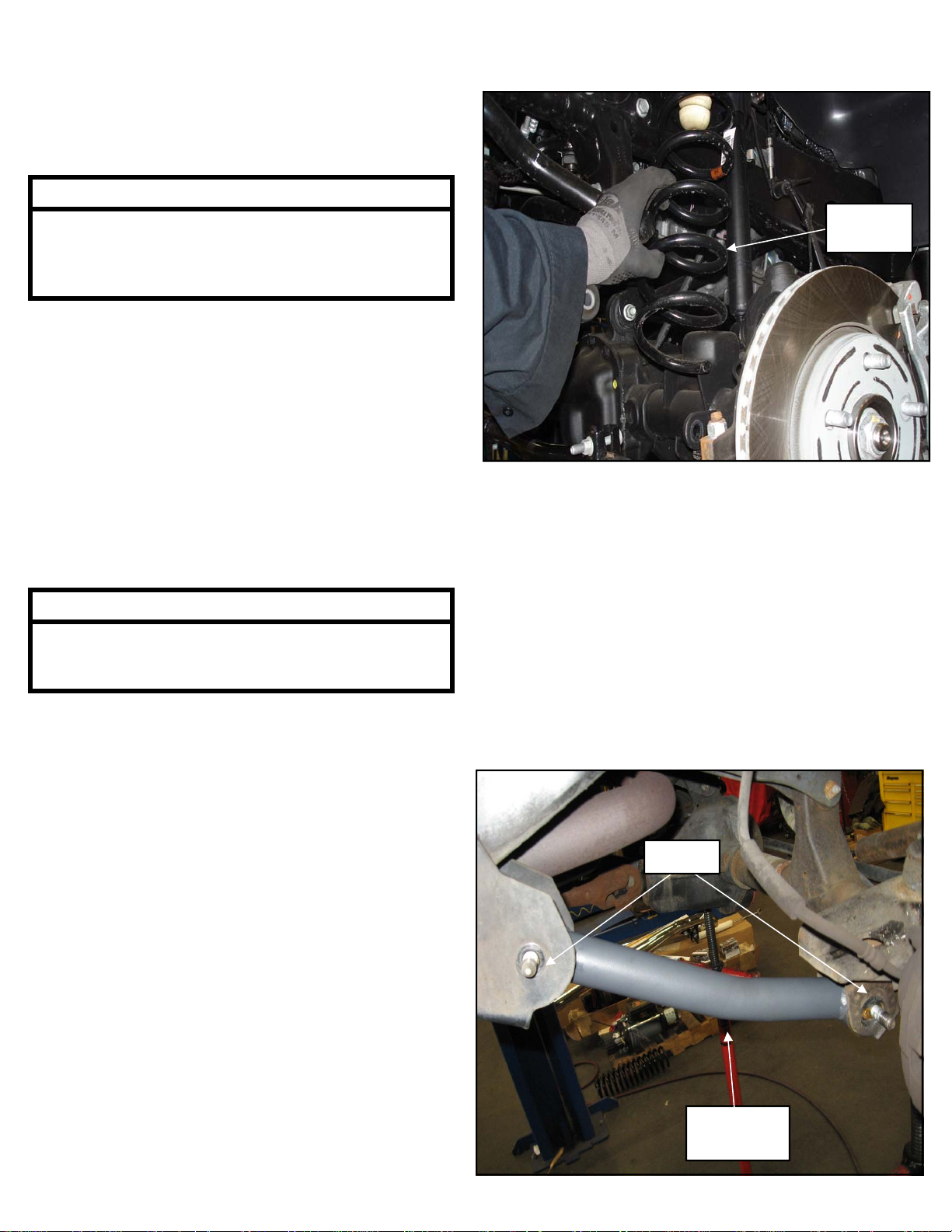
3. Disconnect the track bar from the axle and save
the hardware for reuse.
OE Coil
Spring
Install Front Suspension
1. On the passenger side, with the axle supported,
remove the passenger side lower control arm
from the vehicle. Be sure to leave the driver
side control arms in place to keep the front axle
from rolling over
2. Install the arm (82-TM30011) into the mounting
pockets on the frame using the previously removed OE bolts and hardware.
4. Unbolt the front brake line brackets from the
frame. Save the hardware for reuse.
5. Unbolt the front sway bar end links and remove
them from the vehicle. Save the hardware for
reuse.
6. Remove the shocks on both sides of the vehicle.
It may be necessary that you slightly raise the
axle to unload the shocks for removal. Save the
hardware for reinstallation.
7. If your vehicle came equipped with a skid plate
loosen the driver side bolt and remove the (2)
passenger side bolts.
8. Lower the jack carefully, remove the OE coil
springs and the OE isolators. Label the springs
as to which side they were removed, Left and
Right so that they are reinstalled in the side in
which they were removed.
OE Bolts
82-TM30011
Control Arm
4
Page 5

3. Repeat steps 1 and 2 on the remaining side of
the vehicle.
4. Carefully lower the front axle to ease in the new
coil spring installation. Using the factory isolators install the coil springs (TM3440-60010) into
the spring buckets
TM3440-60010
Coil Spring
7. Assemble the front sway bar end links (82TM30014) by install bushings (45359) in the
top and bottom of the sway bar end links. In-
stall the 5/8” sleeve (61150) into the top sway
bar end link bushings only.
Sway Bar
35-TM20015
Adapter
Bracket
3/8” x
2 1/2”
Bolt
82-TM30014
Sway Bar End
Link
35-TM30018
Spacer
3/8” x
1 1/2”
Bolt
5. Raise the front axle into place. Make sure the
coil spring seats properly on the lower spring
perch.
6. Install your new front shocks (TM73245011) and
install the lower shock mount to the axle mount
using the previously removed OE hardware.
TM73245011
Front Shock
OE
Axle
Mount
Bolt
8. Install the sway bar adapter bracket (35TM20015) onto the sway bar using the 3/8” X 1
1/2” bolt, spacer (35-TM30018) and hardware.
9. Install sway bar end links (82-TM30014) into the
adapter (35-TM20015) using the 3/8” X 2 1/2”
bolt and hardware. The jog in the sway bar will
face towards the outside of the vehicle.
10. Secure the sway bar end link lower mount to the
axle mount using the previously removed OE
bolts and hardware.
11. Reinstall the brake line drops to the frame using
the previously removed OE hardware.
12. Install shifter drop bracket (35-TM20014) to
pivot bracket using 6mm hardware provided.
Install assembly into the existing mounting location using hardware previously removed.
5
Page 6

NOTE
Prepare to Install Rear
You may need to adjust the 4WD rod to engage
the 4WD. It is very important that the shifter
pivot rod protrudes through the self-aligning
bearing on the pivot bracket approximately 3/8”.
By bending the opposite bracket on the Transfer
Case, you can easily achieve this.
35-TM20014
Shifter Drop
13. On both sides of the vehicle, check the routing
of the brake lines and the ABS wire harnesses.
There must be no pinching, rubbing, or
stretching of either component. Use zip ties to
secure these items to the steering components.
At full droop, cycle the steering from lock to lock
while observing the reaction of these
components. Reposition them if needed.
14. Reinstall the front wheels and lower the vehicle
to the ground. Torque the lug nuts according to
the wheel manufacturers recommendations.
15. Reattach the skid plate using the (2) supplied 1”
spacers (90-TM10002) and 12mm x 80mm
bolts and hardware. Tighten hardware to 55 ft/
lbs.
16. Install the OE the track bar assembly into the
passenger side axle track bar mount using the
previously removed OE track bar bolt and hardware. Torque according to manufacturers specifications.
17. Reinstall the wheels and lower the vehicle to the
ground. Torque the lug nuts to factory specifications.
Suspension
1. Loosen, but do not remove, lug nuts on each
front wheel.
2. Jack the rear of the vehicle with the floor jack
under the differential and place jack stands under the frame just in front of the lower control
arm frame mounts. Leave the jack stands high
enough to let the floor jack down and still have
the rear tires suspended in the air. Keep the
floor jack under the differential with slight pressure for support.
3. Remove the rear wheels.
4. Unbolt and remove the rear track bar from the
vehicle. Save the hardware for reuse.
5. Unbolt and remove the rear shocks from the vehicle. Save the hardware for reuse.
6. Unbolt the sway bar end links and remove
them from the vehicle. Save the hardware for
reuse.
7. Unbolt the brake line bracket from the frame.
Save the hardware for reuse.
8. Unclip the ABS line from the axle.
9. Lower the rear differential so that the springs
come loose. Remove the OE coil springs and
the OE isolators. Label the springs as to which
side they were removed, Left and Right so that
they are reinstalled in the side in which they
were removed.
Install Rear Suspension
1. Install the rear track bar relocation bracket (82TM20013) into the original track bar mounting
pocket using the supplied 1/2” x 3” bolt and
supplied spacer (35-TM30013).
18. Torque all bolts to factory specifications. Retorque all bolts after 500 miles.
2. Use the holes in the track bar bracket as a guide
to center punch and drill the mounting holes in
the axle mounting pocket. Drill the holes using a
5/16” drill bit.
6
Page 7

82-TM20013
Rear Track Bar
Bracket
9. Raise the rear differential and make sure that
the coil springs are in their saddles.
TM3440-60020
Rear Coil
Spring
35-TM30013
Sleeve
Holes to be
Drilled
1/2” X 3”
Bolt
5/16”
Drill Bit
3. Secure the track bar relocation bracket to the
axle mounting pocket using the supplied 5/16” X
1” bolts and hardware.
4. Torque the 5/16” hardware to 25 ft./lbs. and the
OE bolt to 125 ft./lbs.
5. On the passenger side, with the axle supported,
remove the passenger side lower control arm
from the vehicle. Be sure to leave the driver
side control arms in place to keep the front axle
from rolling over
6. Install the rear arm (82-TM30011) into the
mounting pockets on the frame using the previously removed OE bolts and hardware.
7. Repeat steps 5 and 6 on the remaining side of
the vehicle.
8. Carefully lower the rear axle to ease in the new
coil spring installation. Using the factory isolators install the coil springs (TM3440-60020) into
the spring buckets
10. Install transfer case drop spacers by supporting
one side of transfer case with floor jack. Remove the OE hardware from the other side of
cross member. Install 1” spacers (90-TM10002)
using the supplied hardware. (‘97-’02 will use
1/2” bolts and ‘03-’06 use 12mm bolts) Tighten
hardware to 55 ft/lbs.
11. Reinstall the rear track bar to the track bar
bracket (82-TM20013) using the previously removed OE hardware.
12. Assemble the rear sway bar end links (82-
TM30016) by install bushings (600001) in the
top and bottom of the sway bar end links. In-
stall the 5/8” sleeve (60859H) into the top
sway bar end link bushings only.
13. Install sway bar end links (82-TM30016) into the
OE frame and sway bar mounting locations using the previously removed OE bolts and hardware.
7
Page 8

Frame
Mount
OE
Bolt
OE
Bolts
82-TM30016
Sway Bar End
Link
OE
Bolt
14. Reinstall the brake line drops to the frame using
the previously removed OE hardware.
15.The transfer case and transmission are sup-
ported by the skid plate. Before removing the
skid plate ensure that the transmission is properly supported. Remove the (6) OE bolts connecting the skid plate to the frame. Reinstall
transfer case skid plate with transfer case spacers (90-TM10002) and supplied 1/2” x 2 1/2” or
12mm hardware from (90-TM60014). Torque
bolts to 55 ft./lbs.
NOTE: With the suspension at full droop,
the front driveshaft will need to be checked
for contact with the skid plate. If contact is
made, the skid plate cannot be reinstalled.
16. Install the rear shock (TM73235002) to the vehicle using the previously removed OE hardware.
Torque according to manufacturers specifications.
90-TM10002
T-Case Spacers
TM73235002
Rear Shock
17. Reinstall the brake line drops to the frame using
the previously removed OE hardware.
18. Reconnect the OE rear track bar to the rear
track bar bracket using the previously removed
OE bolt and hardware. Torque to factory specifications.
19. At full droop, cycle the steering from lock to lock
while observing the reaction of these
components. Reposition them if needed.
20. Reinstall the rear wheels and lower the vehicle
to the ground. Torque the lug nuts to factory
specifications.
21. Recheck the wheel lug torque on all four wheels
at this time.
22. Recheck all hardware for proper installation and
torque at this time.
23. On completion of the installation, have the head-
lights re-aligned.
24. Test drive and note location of steering wheel.
1/2” x 2 1/2” Bolts
25. Adjust drag link to center steering wheel.
26. Align vehicle as soon as practical to minimum
factory caster and maximum factory toe-in
specifications.
27. After 100 miles recheck for proper torque on all
newly installed hardware.
28. Recheck all hardware for tightness after off road
use.
8
Page 9

After Completing Installation
Engine Compartment
1. Connect both battery cables. Connect positive
cable first, then negative cable.
WARNING
Re-torque all fasteners after 500 miles and after
off road use. All suspension lift components
should be visually inspected and fasteners retorqued during routine vehicle servicing.
Miscellaneous
1. Adjust headlights.
2. Check all fasteners to ensure they are tight.
3. Ensure all wires, hoses, cables, etc. are prop-
erly
connected and there is ample slack.
4. Align vehicle to OE specifications. Retain alignment
results.
Dynamic Vehicle Check
1. Check steering and suspension in all positions
to ensure that there is no bind and adequate
clearance between all moving, fixed, and heated
members. Check operation of clutch, brake system, and parking brake. Check operation of transmission and transfer case. Ensure there is full engagement in all gears and 4WD ranges. Check
battery connections and electrical component operations. Test-drive vehicle.
CAUTION
Trail Master does not recommend any particular
wheel and tire combinations for use with its suspension lifts and cannot assume responsibility for
the customer’s choice of wheels and tires. Refer
to your owner's manual for recommended tire
sizes and warnings related to the use of oversized tires. Larger wheel and tire combinations
increase stress and wear on steering and suspension components, which leads to increased
maintenance and higher risk for component failure. Larger wheel and tire combinations also alter speedometer calibration, braking effectiveness, center of gravity, and handling characteristics. Consult an experienced local off road shop
to find what wheel and tire combinations work
best with your vehicle.
NOTE
All warranty information, instruction sheets, and
other documents regarding the installation of this
product must be retained by the vehicle owner.
Information contained in the instructions and on
the warranty card will be required for any warranty claims. The vehicle owner needs to understand the modifications made to the vehicle and
how they affect vehicle handling and performance. Failure to provide the customer with this
information can result in damage to the vehicle
and severe personal injury.
9
Page 10

Kit Parts List:
TM3440-20013 Kit:
1 4” Coil Spring (TM3440-60010, front)
1 4” Coil Spring (TM3440-60020, rear)
2 Absorber (shock, front, TM73245011)
2 Absorber (shock, rear, TM73235002)
Box TM3440-20013-1
1 Track Bracket (Rear, 82-TM20013)
1 Sleeve (35-TM30013, Rear)
1 90-TM60010 Hardware bag,
1 Bolt (1/2” x 3” Gr. 8)
2 Flat Washer, (1/2”)
1 Nylock Nut, (1/2”)
1 Bolt (3/8” x 1” Gr. 8)
2 Flat Washer, (3/8”)
1 Nylock Nut, (3/8”)
3 Bolt (5/16” x 1” Gr. 8)
6 Flat Washer, (5/16”)
3 Nylock Nut, (5/16”)
2 Shifter Drop Bracket (35-TM20014)
1 90-TM60011 Hardware bag,
4 Button Head Bolt (M6– 1.0 x M29)
4 Nylock Nut, (M6-1-0)
8 Flat Washer, (M6)
2 Sway Bar End Link (Front, 82-TM30014)
1 90-TM60012 Hardware bag,
4 Bushings (sway bar front, 45359)
4 Bushings (sway bar rear, 600001)
2 5/8” Sleeve (60859H, Rear)
2 5/8” Sleeve (61150, Front)
2 Sway Bar Adapter (Front, 35-TM20015)
2 Sway Bar End Link (Rear, 82-TM30016)
2 Spacer (35-TM30018, front sway bar)
1 90-TM60013 Hardware bag,
2 Bolt (3/8” x 1 1/2” Gr. 8)
2 Bolt (3/8” x 2 1/2” Gr. 8)
4 Nylock Nut, (3/8”)
4 SAE Flat Washer, (3/8”)
2 USS Flat Washer, (3/8”)
4 Lower Control Arms (35-TM30011)
1 90-TM60014 Hardware bag, (Transfer-Case)
6 Bolt (1/2 x 2 1/2” x 2” Gr. 8)
6 Bolt (M12-1.75 x M55)
6 USS Flat Washer, (1/2”)
8 Spacer (T-Case 1”, 90-TM10002)
1 90-TM60015 Hardware bag, (Skid Plate)
2 Bolt (M12-1.75 x 80mm 10.9)
2 Split-Lock Washer, (M12-1.75)
2 Flat Washer, (M12)
(Rear Track Bar)
(Shifter Drop)
(F & R Sway Bar)
(F & R Sway Bar)
2 Not Used in 97-02 Models
10
Page 11

Revision Page:
11
Page 12

Notice to Owner Operator, Dealer and Installer:
Vehicles that have been enhanced for off-road performance often have unique handling characteristics
due to the higher center of gravity and larger tires. This vehicle may handle, react and stop differently than
many passenger cars or unmodified vehicles, both on and off–road. You must drive your vehicle safely!
Extreme care should always be taken to prevent vehicle rollover or loss of control, which can result in serious injury or even death. Always avoid sudden sharp turns or abrupt maneuvers and allow more time and
distance for braking! Trail Master Suspension
reminds you to fasten your seat belts at all times and reduce speed! We will gladly answer any questions concerning the design, function, maintenance and correct use of our products.
Please make sure your Dealer/Installer explains and delivers all warning notices, warranty forms
and instruction sheets included with Trail Master Suspension
product.
Application listings in this catalog have been carefully fit checked for each model and year denoted. However, Trail Master Suspension
reserves the right to update as necessary, without notice, and will not be
held responsible for misprints, changes or variations made by vehicle manufacturers. Please call when in
question regarding new model year, vehicles not listed by specific body or chassis styles or vehicles not
originally distributed in the USA.
Please note that certain mechanical aspects of any suspension lift product may accelerate ordinary wear of original equipment components. Further, installation of certain Trail Master Suspension
products may void the vehicle’s factory warranty as it pertains to certain covered parts; it is the consumer’s responsibility to check with their local dealer for warranty coverage before installation of the lift.
Warranty and Return policy:
Trail Master Suspension
materials. Trail Master Suspension’s
Trail Master Suspension’s
warranties its full line of products to be free from defects in workmanship and
obligation under this warranty is limited to repair or replacement, at
option, of the defective product. Any and all costs of removal, installation,
freight or incidental or consequential damages are expressly excluded from this warranty. Trail Master
Suspension is not responsible for damages and / or warranty of other vehicle parts related or non-related
to the installation of Trail Master Suspension
product. A consumer who makes the decision to modify his
vehicle with aftermarket components of any kind will assume all risk and responsibility for potential damages incurred as a result of their chosen modifications. Warranty coverage does not include consumer
opinions regarding ride comfort, fitment and design. Warranty claims can be made directly with Trail Mas-
ter Suspension or at any factory authorized Trail Master Suspension dealer.
IMPORTANT! To validate the warranty on this purchase please be sure to mail in the warranty card.
Claims not covered under warranty-
• Parts subject to normal wear; this includes bushings, bump stops, ball joints, tie rod ends and heim joints
• Discontinued products at Trail Master Suspension’s
discretion
• Bent or dented product
• Finish after 90 days
• Leaf or coil springs used without proper bump stops
• Products with evident damage caused by abrasion or contact with other items
• Damage caused as a result of not following recommendations or requirements called out in the installation manuals
• Products used in applications other than listed in Trail Master Suspension’s
catalog
• Components or accessories used in conjunction with other manufacturer’s systems
• Warranty claims without “Proof of Purchase”
• Trail Master Suspension
accepts no responsibility for any altered product, improper installation, lack of
or improper maintenance, or improper use of our products.
E-Mail: info@trailmastersuspension.com
Website: www.trailmastersuspension.com
Ph: (877) 695-7812
12
 Loading...