

Page 1

400 W. Artesia Blvd. Fax: (310) 747-3912
Compton, CA 90220 Ph: (877) 695-7812
www.trailmastersuspension.com
CHEVEROLET SILVERADO 4WD/2WD 6” SUSPENSION LIFT KIT
‘07- ’13 KIT# TM103N
WARNING
Installation of a Trail Master suspension lift kit will
change the vehicle’s center of gravity and handling characteristics both on- and off-road. You must drive the vehicle safely! Extreme care must be taken to prevent vehicle rollover or loss of control, which could result in serious injury or death. Avoid sudden sharp turns or abrupt
maneuvers and always make sure all vehicle occupants
have their seat belts fas tened.
WARNING
Before you install this kit, read and understand all instructions, warnings, cautions, and notes in this instruction sheet and in the vehicle ow ner’ s ma nu al.
CAUTION
Proper installation of this kit requires knowledge of the
factor y reco mme nded proc edur es f or r emo val an d i nsta llation of original equipment components. We recommend
that the factory shop manual and any special tools
needed to service your vehicle be on hand during the
installation. Installation of this kit without proper knowledge of th e fac tor y rec omme nded proc edur es ma y af fect
the performance of these components and the safety of
the vehicle. We strongly recommend that a certified mechanic familiar with the installation of similar components
install this kit.
WARNING
Many states and municipalities have laws restricting
bumper heights and vehicle lifts. Consult state and local
laws to determine if the changes you intend to make to
the vehicle comply wit h the law .
WARNING
The installation of larger tires may reduce the effectiveness of the braking system.
WARNING
Always wear eye protection when operating power tools.
WARNING
Before you install this kit, block the vehicle tires to prevent the vehicle from rolling.
WARNING
DO NOT combine suspension, body, or other lift devices.
Use of vehicle with combined lifts may result in unsafe
and/or unexpected han dling characteristic s.
WARNING
This kit should only be installed on a vehicle that is in
good working condition. Before you install the kit, thoroughly inspect the vehicle for corrosion or deformation of
the sheet metal. If the vehicle is suspected to have been
in a collision or misused, do not install this kit. Off-road
use of your vehicle with this kit installed may increase
the stress applied to the factor y components. Failure to
observe this warning may result in serious personal injury and/or severe damage to your vehicle.
NOTE
Lift height may vary depending on vehicle configuration,
engine size, additional accessories, the factory suspension package, and vehi c l e’s condition.
NOTE
Trail Master recommends using thread locking compound on the threads of all kit nuts and bolts unless
specified otherwise in these instructions.
Page 2

TM103N
Revised
1.28.14
2
Page 3

TM103N
Revised
1.28.14
Before Starting Installation
NOTE
Kit parts are prefaced by the word kit and appear in
bold print.
1. Carefully read all warnings and instructions completely before beginning.
2. Verify all parts have been received in this kit by
checking the parts list at the end of this document.
3. Only install this kit on the vehicle for which it is
specified. If anytime during the installation you encounter something different from what is outlined in
the instructions, call technical support at (877) 695-
7812.
4. Park vehicle on a clean, dry, flat, level surface and
block tires so vehicle cannot roll in either direction.
5. Measure ride height with the vehicle supporting its
own weight on level ground. To settle the suspension,
the vehicle should be driven forward at least 10 feet
immediately prior to taking these measurements. Ride
height is the measurement from the center of the axle
straight up (vertical) to the fender lip. Record this
measurement for all four wheels.
Tire & Wheel Information:
Due to differences in manufacturing, dimensions and
inflated measurements, tire and wheel combinations
should be test fit prior to installation. Tire and
wheel choice is crucial in assuring proper fit, performance, and the safety of your Trail Master
equipped vehicle. For this application, we recommend a 17” or larger wheel not to exceed 8” in width
with a maximum backspacing of 4.5” must be used.
Additionally, a quality tire of radial design, not exceeding 35” tall X 12.5” wide is also recommended.
Please note that the use of a 35” X 12.5” tire may require modification to the front valance. Violation of
these recommendations will not be endorsed as acceptable by Trail Master Suspension and will void
any and all warranties either written or implied.
NOTE
On some vehicles the driver’s side OE chassis wire
harness that connects to the ABS wire may be shorter,
from the factory, than others. If the line needs to be extended GM #19149296 (ACD#PT2232) can be installed
into the chassis wire harness.
Torque Specifications:
See factory service manual for torque values
when reusing OE fasteners.
NOTE
Adhere to recommendations when replacement fasteners, retainers and keepers are called out in the
factory service manual. When re-assembling the vehicle it is recommended by the vehicle manufacturer
that certain fasteners are replaced in order to maintain proper retention characteristics. This system
may not include all replacement hardware as recommended by the factory service manual. Additional
replacement hardware should be obtained prior to
installation of this system to meet the requirements
of the factory service manual.
Engine Compartment
1. Disconnect both battery cables. Disconnect
negative cable first, then positive cable.
Wheel & Tire Requirements
The factory wheel and tire combination will not fit
once this kit is installed.
See factory serv ice manual for torque value s when re-using
OE fasteners.
Bolt Size Grade 5 (ft.-lbs.) Grade 8 (ft.-lbs.)
1/4”-20 10 10
1/4”-28 10 12.5
5/16”-18 17 22.5
5/16”-24 20 25
3/8”-16 30 40
3/8”-24 35 45
7/16”-14 50 65
7/16”-20 55 70
1/2”-13 75 100
1/2”-20 80 115
9/16”-12 105 135
9/16”-18 115 150
5/8”-11 150 195
5/8”-18 160 210
3/4”-16 175 225
3
Page 4

TM103N
Revised
1.28.14
Prepare to Install Front
Suspension
1. Position your vehicle on a smooth, flat, hard surface (i.e. concrete or asphalt). Block the rear
tires and set the emergency brake.
2. Measure and record the distance from the center
of each wheel to the top of its fender opening.
LR: RR:
Record below.
3. Place the vehicle in neutral. Place your floor
jack under the front axle and raise the vehicle.
Place jack stands under the frame rails and
lower the frame onto the stands. Remove the
jack and place the vehicle back in gear, set the
emergency brake, and place blocks both in front
and behind the rear wheels.
4. Remove the front wheels from the vehicle.
5. Unclip the ABS bracket from coil bucket and Aarm. Unplug the ABS connector.
RF: LF:
13. Unbolt the CV axle from the differential.
14. Using the proper tool carefully separate the up-
per ball joint from the knuckle. Loosen but DO
NOT remove the retaining nut from the upper
ball joint.
15. Support the lower control arm with a jack and
unbolt the lower strut mounting bolts from the
lower control arm mount.
16. Unbolt the lower control arm retai ning bolts
17. Unbolt the previously loosened upper ball joint
retaining nut and remove the lower control arm,
knuckle and CV axle assembly from the vehicle.
18. Remove the clips that hold the ABS wire to the
upper strut mounting studs.
19. Unbolt the nuts on the upper strut mounting
studs. Carefully remove the strut from the vehicle.
20. Unbolt the front driveshaft from the differential
and secure it out of the way of the work area.
Save the hardware for reuse.
6. Unbolt the ABS strap from the steering knuckle.
Secure the ABS wire out of the work area. Discard the bracket.
7. Using pliers carefully open the a-arm brake line
retaining bracket. Remove the rubber brake
hose from the bracket. Using a cut off wheel,
cut the bracket at the bend.
NOTE: Be very careful to not damage the
rubber line in any way during it’s removal
from the bracket.
8. Unbolt the brake line bracket from the upper Aarm.
9. Using the proper tool ca refully separate the
outer tie rod end from the knuckle.
10. Remove the brake caliper and caliper bracket
assembly and the rotor. Secure them clear from
the work area. DO NOT
the brake line or damage may result.
11. Mark the orientation of the sway bar and remove
it from the vehicle.
let the caliper hang by
21. Unplug the differential wiring harness clips and
vent tube.
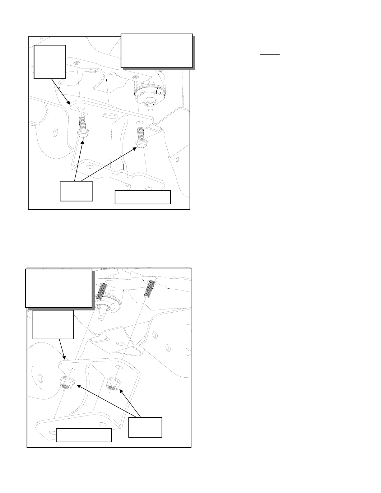
22. Remove the factory rear crossmember support
4WD ONLY!
OE Crossmember
Brace
Illustration 1
Crossmember Removal
12. Unbolt and remove the sway bar end links from
the vehicle.
4
Page 5

Illustration 2
Frame Cut Picture
TM103N
Revised
1.28.14
Driver Side Rear
Lower Control Arm
Mounting Pocket
Illustration 3
Front Differential
Support Bracket Install
Cut
Line
3”
7/16” X 3”
Bolt
Cut
Piece
Driver Side Rear
Lower Control Arm
Mounting Pocket
3”
4WD ONLY!
4WD ONLY!
Sleeve
90-2108
Front Differential
Support Bracket
82-3692
Front Differential
Bushing
15-11148
10mm X 60mm Bolt
5
Page 6
TM103N
Revised
1.28.14
Illustration 4
82-3701
Driver
Diff Drop
Bracket
OE
Hardware
brace from the vehicle and discard. See ILLUSTRATION 1.
23. Support the differential with a jack and unbolt
the driver and passenger side mounts (2 per
side). Carefully remove the differential from the
Drvr Side Differential Drop
Bracket Install
4WD ONLY!
Illustration 5
4wd Pass Side
Differential Drop Bracket
82-3704 Pass
Diff Drop
Bracket
vehicle.
24. On the driver side ONLY, measure out from the
edge of the rear factory crossmember brace
mount approximately 3” and scribe a line. See
ILLUSTRATION 2.
25. Using a suitable cutting tool, (abrasive cutoff
wheel, Sawz-all, etc.) cut the frame along the
previously marked lines as shown in ILLUSTRATION 2.
Install Front Suspension
1. Assemble the front differential support bracket
(82-3692) using the supplied bushings (15-
11148) and sleeves (90-2108) from hardware
pack (90-6515). See ILLUSTRATION 3.
2. Rotate the front differential until the case bolt
heads are oriented up. Carefully remove the factory bolts from the diff erential as shown in ILLUSTRATION 3.
NOTE: You will probably notice some dif-
ferential oil seeping from the area where the
bolts are removed. This is normal and not
something to worry about.
If you do not stand the differential as directed, you will see a LOT more oil on your
floor.
3. Place front differential support bracket (82-
3692) on the front differentia l as shown in IL-
LUSTRATION 3. Secure support bracket using
the supplied 10mm X 60mm bolts and washers,
7/16” X 3” bolt and hardware from pack 90-
6251. Torque these fasteners to 32 ft. lbs. See
ILLUSTRATION 3.
4WD ONLY!
OE
Hardware
4. Install the driver side differential drop (82-
3701) into the factory frame location using the
OE bolts and hardware. Hand tighten only.
ILLUSTRATION 4.
5. Using the OE hardware, install the passenger
side differential drop (82-3704) to the factory
frame location as shown in ILLUSTRATION 5.
IMPORTANT: The bracket is slightly ta-
pered. The short end of the taper is oriented toward the rear of the vehicle.
6
Page 7

TM103N
Revised
1.28.14
Illustration 6
4wd Differential Install
82-3704 Pass
Diff Drop
Bracket
9/16” X
1 3/4”
Bolts
OE Bolt
82-3701
Drvr Diff
Drop
Bracket
Differential
4WD ONLY!
1/2” X
1 3/4”
Bolts
Illustration 7
Front Crossmember
Install
31. Secure the differential to the previously installed
drop brackets (82-3701 Drvr and 82-3704 Pass)
using the supplied hardware. Snug all differential mounting hardware to secure the differential
location at this time, but DO NOT
torque at this
time. See ILLUSTRATIONS 6.
32. Check clearance between the differential and the
trimmed area of the frame. If needed, remove
more material until adequate clearance is
achieved.
33. After verifying there is an adequate amount of
clearance, thoroughly clean and paint the
trimmed areas with a good quality paint to prevent rust.
34. Install the front crossmember (82-TM9511 48)
into the front mounting pockets by sliding one
end of the crossmenber into the driver side
mounting pocket from the outside. Push the installed end of the crossmember as far as it will
go to the passenger side in the mounting pocket.
Swing the crossmember up into the passenger
side pocket. Center the crossmember in the
mounting pockets and secure using the OE
bolts. See ILLUSTRATION 7.
NOTE: DO NOT
cut the front crossmember frame mounting pockets.
NOTE: On 2WD model, sandwich the
lower mounting portion of the skid plate in between the frame and the front cross m ember.
82-TM951148 Front
Crossmember
OE Bolt
35. Install the front differential tabs (82-3691), from
hardware pack (90-6516), to the upper holes in
the welded mounting tabs on the front crossmember using the supplied 5/16” X 1” bolts and
hardware. See ILLUSTRATION 8.
NOTE: Be sure to bolt the tabs (82-3691)to
the outside of the welded crossmember mounting
tabs.
36. Secure the diff mount tabs to the front differen-
tial support bracket (82-3692) using the using
the 9/16” X 4” bolt and hardware.
37. Install the rear crossmember (82-3688) into the
rear mounting pockets using the OE bolts. See
ILLUSTRATION 9.
NOTE: Be sure to check for clearance
against the frame.
7
Page 8

Illustration 8
Front Differential Mount Tab
Install
9/16” X 4”
Bolt
82-3691
Front Diff
Mount Tab
Mount to Upper
Holes In Front Crossmember Mount Tabs
TM103N
Revised
1.28.14
9/16” X 4”
Bolt
5/16”
X 1”
Bolt
82-3691
Front Diff
Mount Tab
5/16”
X 1”
Bolt
4WD ONLY!
38. Reinstall the front driveshaft to the front differ-
ential using the previously removed OE hardware.
39. Reattach the wiring harness, wiring clips and the
vent tube to the differential.
IMPORTANT: Secure the vacuum line out
of the way of the steering rack.
NOTE: The differential vent tube may need
to be carefully pulled down to provide more slack
for it’s new mounting position.
40. Unbolt the CV axle retaining nut and remove the
CV axle from the OE knuckle.
5/16”
X 1”
Bolt
Finished View
bench, remove the bearing hub assembly from
the OE knuckle by removing the OE bolts .
Save the mounting bolts, bearing, and dust
shield for re-use. Discard the OE knuckles.
43. Reassemble the bearing hub and brake dust
shields into the new Trail Master steering
knuckle (90-4491 Drvr and 90-4492 Pass).
Make sure that the ABS wiring is oriented in
exactly the same position as it came from the
OE knuckle and out of the way of the tire.
44. Torque the bearing to the knuckle with the OE
bolts. Torque to 133 ft./lbs. Repeat on the other
side.
41. Separate the knuckle from the lower control arm
and remove the OE knuckle.
42. Disassemble the OE knuckle on your work
45. Install the lower A-arms into the crossmember
mounting pockets. Secure using the supplied
5/8” X 4 1/2” bolts and hardware in the front
pocket and the supplied 5/8” X 5 1/2” bolts and
8
Page 9

OE Bolt
TM103N
Revised
1.28.14
5/8” X 5
1/2” Bolt
82-3688 Rear
Crossmember
Illustration 9
Rear Crossmember
hardware in the rear pocket.
46. Install the new knuckle to the lower ball joint.
Torque the lower ba ll joint nut 74 ft./lbs.
47. Slide the CV spacer ring (90-3809) onto the
splined end of the outer CV axle. Be sure that
the tapered end of the ring is facing toward the
inside of the axle. Slip th e CV axle through the
bearing hub in the knuckle from the inside.
48. Secure the CV axle and the CV spacer (90-
4077) to the differential using the supplied
10mm X 60mm bolts and washers. See ILLUS-
TRATION 11.
49. Install the new knuckle to the upper ball joint.
Start the nut and leave hand tight until Coil over
installation is complete.
50. Reinstall the CV shaft washer and retaining nut
to CV axle. Torque this nut to factory specifica-
5/8” X 4
1/2” Bolt
Illustration 10
Lower A-Arm Install
tions. (See your GM service manual for details)
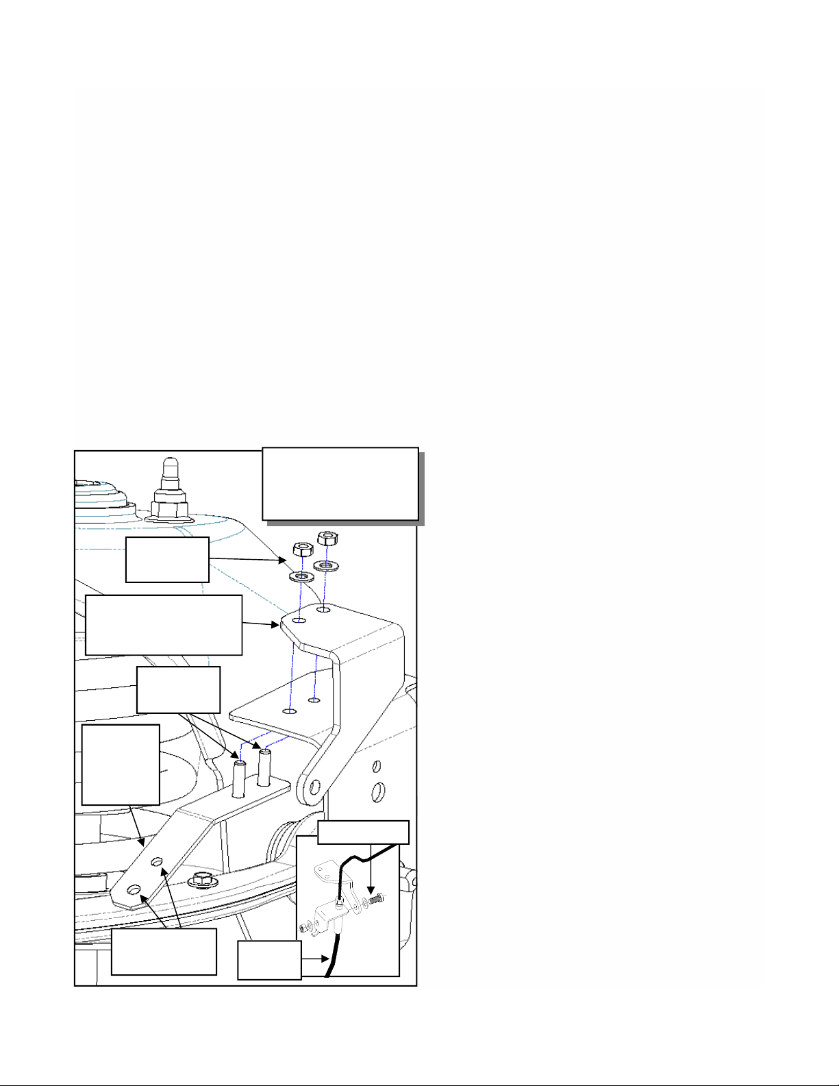
51. At ta ch the strut spacer (82-2614) to the top of
the strut using the OE hardware. Torque to
manufacturers specifications. See ILLUSTRATION 12.
52. Fit the strut and spacer assembly into the stock
mounting locations. Fasten using the supplied
hardware on the top from hard ware pack (90-
6317) torque to 45-50 ft./lbs. See ILLUSTRA-
TION 12.
NOTE: Be sure that the locating tab on the
top ring of the strut spacer is facing toward the
outside of the vehicle.
IMPORTANT!: Be sure the OE wiring
harness clips are reinstalled to the strut spacer
studs. Failure to do so may result in the wiring
harnesses being damaged by the steering column.
Illustration 11
CV Spacer Install
CV
spacer
ring
(90-3809)
Outer CV
10mm X 60mm Bolts (6)
4WD ONLY!
9
90-4077 CV
Spacer
Page 10
TM103N
Revised
1.28.14
7/16”
Hardware
Illustration 12
Strut Spacer Install
Be Sure the
Location
Tab is
Facing Out
OE
Hardware
82-2614
Coil
Spacer
Installed View
OE Strut
53. Secure the lower strut cross pin to the lower A-
arm using the OE bolts. Torque the bolts according to the manufacturers specifications.
54. Torque the upper ball joint nut to 37 Ft./lbs.
55. Be sure to re-clip the previously removed upper
strut mount wiring away from any moving parts,
steering shaft or exhaust manifolds.
56. Work on one side of the vehicle at a time.
57. Torque all the differential, upper crossmember
bolts and coil over hardware according to the
torque chart on page 3 or to factory specifications. DO NOT
torque the lower A-arm until
the vehicle is on the ground.
58. Unbolt the rubber brake line bracket from the
upper coil bucket. Discard the OE bolt.
59. Unclip the OE metal brake lines from the frame
clips and carefully bend to provide enough slack
in the line for it’s new posit ion.
NOTE: Be sure that the metal lines do not
rub or contact anything.
60. Install the ABS line relocation bracket (90-
7876) studs, from the bottom, into the existing
holes in the rear of the upper control arm pocket.
Install the brake line relocation bracket (90-7734
drvr and 90-7735 pass) to the ABS relocation
bracket mounting studs. Secure using the sup-
plied 1/4” washers and nuts. See ILLUSTRATION 13.
61. Bolt the brake line to the previously installed
brake line relocation bracket (90-7734 drvr and
90-7735 pass) using the supplied 5/16” X 1”
bolt. See ILLUSTRATION 13.
62. Reinstall the rotors and brake calipers to the new
knuckle using the previously removed OE bolts.
Be sure to use thread locker on the caliper
bracket mounting bolts. Torque to factory
specifications.
NOTE: It may be necessary to carefully
bend the caliper banjo fitting slightly up to provide adequate slack for the brake line. Be very
careful not to damage the banjo fitting or
brake line in any way. Check tightness of
10
Page 11
TM103N
Revised
1.28.14
banjo bolt after modification.
63. Route the ABS wire through the factory clips on
the upper A-arm. Secure the ABS line to relocation bracket (90-7876) mounting holes. The
ABS line plastic push pin will install to one hole
and the locating tab will install into the remaining hole. See ILLUSTRATION 13.
NOTE: On some vehicles the driver’s side
OE wire harness that connects to the ABS wire
may be shorter, from the factory, than others.
If the line needs to be extended GM #19149296
(ACD#PT2232) can be installed into the chassis wire harness.
64. Reattach the ABS wiring and secure it to the top
hole on the knuckle using the supplied Adel
clamp and supplied OE bolt and washer. See
ILLUSTRATION 13.
NOTE: The Adel clamp has a flat side and
Illustration 13
Brake Line Relocation
Bracket Install and Routing
1/4”
Hardware
Front Brake Line Drop
Bracket 90-7734 drvr and
90-7735 pass
Mounting
Studs
ABS
Relocation
Bracket
90-7876
5/16” X 1” Bolt
a rounded side, make sure the flat side is facing
out toward the tire.
65. On both sides of the vehicle loosen the jam nut
and remove the outer tie rod ends and jam nuts.
66. The inner and outer tie rod ends may need to be
shortened. Measu re in 9 /16” from the end of the
inner tie rod end and scribe a line. Measure in
7/16” from the end of the outer tie rod end and
scribe a line. Using a suitable cutting tool,
(abrasive cutoff wheel, Sawz-all, etc.) cut the
ends along the previously marked line. Be sure
the cut is made straight and square or else the
jam nut will not hold it’s torque properly.
67. Install the supplied 16mm jam nuts onto the in-
ner tie rods. Thread the jam nut and outer tie
rod ends on as far as they will go on the inner tie
rods with the stud facing down.
68. Reinstall the outer tie rod ends onto the inner tie
rod ends. Thread them on as far as they will go
with the stud facing down.
69. Insert from the top and secure the tie rod end to
the knuckle and torque to factory specifications.
Be sure to clean the threads and use thread locking compound on the tie rod end nut.
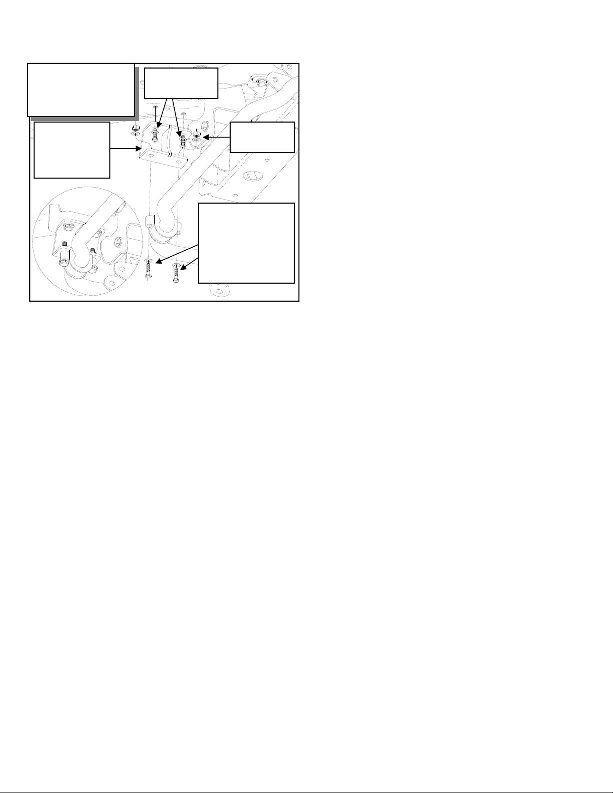
70. Install the sway bar drop brackets (82-3632
drvr and 82-3635 pass) to the original sway bar
mounting holes in the frame, angled toward the
rear of the vehicle, using the supplied 10mm-1.5
X 30mm bolts and hardware. See ILLUSTRATION 14.
71. Using the previously made sway bar orientation
markings as a guide, flip the sway bar 180 degrees and reinstall it to the sway bar drop brackets using the supplied 7/16” X 2 1/2” bolts and
hardware for 2007-2009 models or the previ-
ously removed OE bolts and 10mm flat washers
and 10mm nuts for 2010-2012 models. Leave
hardware loose at this time. See ILLUSTRATION 14.
ABS Line
Mounting Holes
OE Brake
Line
72. Install the previously removed OE sway bar end
links into their original location on the lower Aarms. See ILLUSTRATION 14.
73. Reconnect the sway bar end links to the sway
bar.
74. Torque the sway bar hardware according to the
11
Page 12
TM103N
Revised
1.28.14
Illustration 14
Sway Bar Drop Bracket
Install
Sway Bar Drop
Bracket 823632 drvr and
82-3635 pass
10mm X 30mm
Bolts
(4) 7/16” nut
or 10mm nut
For 2007-2009 models:
Use the 7/16” X 2 1/2”
bolts
For 2010-2011 models:
Use the OE bolts and
10mm washers and
10mm nuts
torque chart on page 3.
75. On both sides of the vehicle, check the routing
of the brake lines and the ABS wire harnesses.
There must be no pinching, rubbing, or
stretching of either component. Use zip ties to
secure these items to the steering components.
At full droop, cycle the steering from lock to
lock while observing the reaction of these
components. Reposition them if needed.
recommendations.
79. With the truck on the ground torque the lower
A-arm bolts according to the torque chart on
page 3.
80. Center the steering wheel and lock it in place.
Set the toe by adjusting the tie rod ends properly.
IMPORTANT!: If the steering wheel and
front wheels are not centered properly it will
trigger the anti-lock brake and traction control
warning lights.
81. Lock the outer tie rod ends by tightening the
16mm jam nuts.
82. Recheck all hardware for proper installation
and torque at this time.
IMPORTANT! BE SURE TO BRING
THE VEHICLE IMMEDIATELY TO A REPUTABLE ALIGNMENT SHOP TO BE ALIGNED!
76. On some vehicles the driver’s side OE wire harness that connects to the ABS wire may be
shorter, from the factory, than others. If the line
needs to be extended GM #19149296
(ACD#PT2232) can be installed into the chassis
wire harness. Check the harness at full droop, if
it is too tight it may cause the ABS light to activate.
77. With the front wheels installed cycle the steering from lock to lock to check to make sure the
front wheels have enough clearance in the
wheel well. If the wheel contacts the front or
rear of the wheel well some trimming will be
necessary. Check the caliper banjo fitting to
ensure the line has the proper amount of slack.
NOTE: Remove OE rotor/drum retaining
clips from wheel studs before installing the
wheels.
78. Lower the vehicle to the ground. Torque the
lug nuts according to the wheel manufacturers
12
Page 13
Prepare to Install Rear
TM103N
Revised
1.28.14
4. Unclip the rubber ABS line from the frame
rails.
Suspension
1. Raise the rear of the truck enough for the tires
to clear the ground and use jack stands on the
frame to support the truck. Remove the rear
tires and wheels.
2. Carefully remove the OE shock absorbers. It
may be necessary to raise the differential housing slightly to facilitate their removal.
3. Unbolt the driver side emergency brake line
hanger from the frame rail. Save the OE bolt
for reuse.
Illustration 15
Rear Leaf Spring Assembly
13-90087
U-Bolts
5. Unbolt the rear brake line bracket from the rear
axle differential housing. Save the OE bolt for
reuse.
6. One side at a time, support the differential
housing on the side being modified. Remove
the “U” bolts from that axle end and discard.
Carefully lower the differential away from the
OE springs. Remove and discard the OE riser
block from its mount pad. Take careful note of
the position of the factory spring packs.
ADD-A-LEAF (13127-1) INSTALLATI ON
NOTE: In order to properly install the
add-a-leaf spring, it will be necessary to contain
the elasticity in the leaf spring with “C” clamps
97-380 Center
Pin Bolt
High Nuts and
Washers PN
20-65302
Install the add a leaf (13127-1) in
the factory spring pack, above a
leaf that is shorter and below one
that is longer than the new one.
Follow the enclosed instructions.
Depending on your truck this
may fall in a spot other than
shown.
Helper leaf assembly.
Do not install in or
below this assembly.
4” Lift Block
PN 95-401
Front of vehicle
13
Page 14

when the center bolt is removed. Some springs
have a factory helper spring consisting of one or
more flat leaves installed at the bottom of the leaf
pack. DO NOT install the add-a-leaf spring in or
below the helper spring.
Install Rear Suspension
1. Hold the spring assembly securely together
with “C” clamp. If necessary remove any
spring leaf alignment clamps. Remove the
spring center bolt. A hammer and drift punch
may be used to drive it out if necessary.
2. Carefully remove “C” clamps and lay unassembled leaves aside.
NOTE: Add-a-leaf will be placed in the
spring assembly progressively according to
length. For example, if the existing leaves are
32” long and 25” long and the add-a-leaf is
28” long, place the add-a-leaf between the existing leaves.
3. Apply a small amount of grease to the end of
the add-a-leaf, place it in the spring assembly
as described in the note above, and reassemble
the leaf springs using the “C” clamps. Insert
the new center bolt (97-380). Torque the center
bolt nut to 20 ft./lbs. With a hacksaw, cut the
center bolt even with the top of the nut.
NOTE: The short side of the spacer will
face toward the front of the vehicle.
4. Loosely assemble the complete spring assemblies into their respective axle mounts. As
shown in ILLUSTRATION 15, place the
4” (95-401) blocks in position. Make sure the
pin in the block is in the hole of the axle housing spring pad. The short end of the block goes
toward the front of the vehicle. Install the
block so the pinion moves up.
NOTE: The block pin may need to be
ground down so that the block sits flat on the
perch if you are not installing traction bars at
this time.
TM103N
Revised
1.28.14
6. Repeat these steps on the other side of the vehicle.
7. Reattach the emergency brake line hanger to
the frame rail using the previously removed OE
bolt.
8. Bolt the rear brake line extension bracket (90-
3341) to the rear axle differential housing using
the previously removed OE bolt.
9. Carefully rotate the rubber brake line factory
bracket assembly toward the rear of the vehicle
and bolt it to the newly installed extension
bracket (90-3341) using the supplied 5/16” X
1” bolt and hardware from pack (90-6299).
NOTE: Be sure that the metal lines do not
rub or contact the rear end housing.
10. Before installing your new Trail Master shock
absorbers, it is necessary that you check for
adequate clearance. Temporarily install your
Trail Master shocks (TM75820W) into the
shock mounts. Carefully check for clearance
issues. If there are areas that come in contact
with or are very close to your new shocks, carefully remove sufficient material to ensure trouble free operation. Pay particular attention to
the area around the lower shock mount. When
all clearance issues have been resolved, install
your new Trail Master shock absorbers and recheck all fasteners for proper installation and
torque.
11. Install your wheels and tires and lower the vehicle to the ground.
NOTE: Remove OE rotor/drum retaining
clips from wheel studs before installing the
wheels.
12. After installation is complete, double check that
all nuts and bolts are tight. Refer to the char t at
the end of this document for torque specifications. (Do not retighten nuts and bolts where
thread locking compound was used).
5. Install the new “U” bolts (13-90087) over the
leaf spring assembly and using the new washers
and nuts supplied along with the existing spring
plates, torque the U-bolt nuts to 105 ft./lbs. See
Illustration 15.
14
Page 15

TM103N
Revised
1.28.14
Final notes:
1. If new tires are installed that are more than 10% taller than original tires , the spee dometer must be recalibrated for
the rear wheel anti-lock brake system to functi on prop erly . Cont act an authoriz ed GM dealer f or details on
recalibration.
2. With vehicle on the floor, cycle the steering from lock to lock and inspect the steering, suspension and driveline
systems for proper operation, tightness and adequa te c learance. Rechec k brake hose/f itti ngs for leaks. Be sure all
brake lines are long enough for safe operation.
3. Have headlights readjust ed to the prop er s etti ngs.
4. Realign front end to factory specifications. Be sure the vehicle is at the desired ride height prior to realignment.
5. Recheck ALL fasteners at 100 m iles to make sure they have not come loose. Due to the additional wear and tear
created by larger tires and wheels, we recommen d that y ou perio dic ally check t he suspens i on s y stem and steering
components to ensure service life and safe vehicl e operation.
Revision Page:
15
Page 16
Dynamic Vehicle Check
TM103N
Revised
1.28.14
1. Check steering and suspension in all positions
to ensure that there is no bind and adequate
clearance between all moving, fixed, and heated
members. Check operation of clutch, brake system, and parking brake. Check operation of transmission and transfer case. Ensure there is full engagement in all gears and 4WD ranges. Check
battery connections and electrical component operations. Test-drive vehicle.
WARNING
Re-torque all fasteners after 500 miles and after
off road use. All suspension lift components
should be visually inspected and fasteners retorqued during routine vehicle servicing.
Caution:
Larger wheel and tire combinations increase
stress and wear on steering and suspension
components, which leads to increased maintenance and higher risk for component failure. Larger wheel and tire combinations also alter speedometer calibration, braking effectiveness, center
of gravity, and handling characteristics. Consult
an experienced local off road shop to find what
wheel and tire combinations work best with your
vehicle.
NOTES:
⇒ On completion of the installation, have the
suspension and headlights re-aligned.
⇒ After 100 miles recheck for proper torque
on all newly installed hardware.
⇒ Recheck all hardware for tightness after
off road use.
IMPORTANT!: 18” OR LARGER WHEELS
MUST BE USED IN
CONJUNCTION WITH THIS LIFT KIT!
NOTE
All warranty information, instruction sheets, and
other documents regarding the installation of this
product must be retained by the vehicle owner
Information contained in the instructions and on
the warranty card will be required for any warranty claims. The vehicle owner needs to understand the modifications made to the vehicle and
how they affect vehicle handling and performance. Failure to provide the customer with this
information can result in damage to the vehicle
and severe personal injury.
.
16
Page 17

TM103N
Revised
1.28.14
Kit Parts List:
Box TM103N-1
90-6299 HARDWARE PACK: Rear Brake Line 1
70-0311001500 5/16” X 1” GR.5 HEX BOLT 2
72-03100100512 5/16” NYLOCK NUT 2
73-03100030 5/16” SAE FLAT WASHER 4
90-3341 REAR AXLE BRAKE LINE RELOCATION BRACKET 1
95-401 CAST IRON LIFT BLOCK 2
13-90087 9/16” U-BOLT 4
20-65302 HARDWARE PACK:
13-30330 9/16” FLAT WASHER 8
13-10423 9/16” HIGHNUT 8
82-3701 DIFF MOUNT:
82-3704 DIFF MOUNT:
90-4077 CV SPACER
– 4WD only 2
90-6513 HARDWARE PACK:
70-0311001800 5/16”-18 X 1 HEX BOLT GR. 4
72-031100816 5/16”-18 NYLOCK NUT . 4
73-04300034 5/16” SAE FLAT WASHER GR. 8 8
90-6514 HARDWARE PACK:
70-0501751800 1/2"-13 X 1 3/4" HEX BOLT GR. 8 2
72-050100816 1/2"-13 STOVER NUT 2
73-05000034 1/2 " SAE FLAT WASHER GR. 8 4
90-6251 HARDWARE PACK:
70-0564001800 9/16”-12 X 4" HEX BOLT GR. 8 1
70-0561751800 9/16”-12 X 1 3/4" HEX BOLT GR. 8 2
72-056100816 9/16”-12 STOVER NUT 3
73-05600034 9/16” SAE FLAT WASHER GR. 8 4
73-05600034 9/16” HARDENED FLAT WASHER 2
70-0563001800 7/16”-14 X 3” HEX BOLT GR. 8 1
72-056100816 7/16”-14 STOVER NUT 1
73-05600034 7/16” SAE FLAT WASHER GR. 8 2
71-100601251000 M10-1.5 X 60 HEX BOLT GR. 10.9 16
73-01008840 M10 USS FLAT WASHER 16
Box TM103N-2
90-4491 KNUCKLE:
Drvr 1
Box TM103N-3
90-4492 KNUCKLE:
Pass 1
90-6522 HARDWARE PACK:
90-3240 ADEL CLAMP 2
90-6556 HARDWARE PACK:
90-3809 CV KNUCKLE SPACER RING 2
90-6709 HARDWARE PACK:
90-3950 SPARE TIRE WHEEL SPACER 2
U-Bolts 1
Drvr– 4WD only 1
Pass– 4WD only 1
Diff Mount Drvr Crossmember– 4WD only 1
Diff Mount Drvr – 4WD only 1
Differential – 4WD only 1
Adel Clamps 2
CV Knuckle Spacer Ring 1
Spare Tire Wheel Spacer 1
17
Page 18

TM103N
Revised
1.28.14
90-6439 HARDWARE PACK: Tie Rod Jam Nut 1
.160FNFJZ 16mm-1.5 HEX JAM NUT 2
Box TM103N-4
82-3688 REAR CROSSMEMBER 1
82-2614 STRUT SPACER 2
90-6317 HARDWARE PACK: Spacer Mount 1
72-043200810 7/16-20 GR. 8 PLATED HEX NUT 6
73-04300830 7/16 SAE FLATWASHER ZINC 6
73-04300836 7/16 SPLIT LOCK WASHER 6
Box TM103N-5
82-TM951148 FRONT CROSSMEMBER 1
90-6284 HARDWARE PACK:
Crossmember 1
70-0624501800 5/8"-11 x 4 1/2" HEX BOLT GR. 8 2
70-0625501800 5/8"-11 X 5 1/2" BOLT GR. 8 2
72-06200100512 5/8"-11 STOVER NUT 4
73-06200030 5/8" SAE FLAT WASHER 8
90-6498 HARDWARE PACK:
Sway Bar Drop 1
71-100301251000 10mm-1.5 X 30mm 10.9 HEX BOLT 4
73-01010930 10mm 10.9 FLAT WASHER 72-043100816 10mm STOVER NUT–
(4) Not Used on 2007-2009 Models 8
2010-2011 models 4
70-0432501800 7/16"-14 X 2 1/2" GR. 8 HEX BOLT 4
72-043100816 7/16"-14 STOVER NUT 4
73-04300034 7/16" SAE FLAT WASHER 8
82-3632 SWAY BAR DROP–
Drvr 1
82-3635 SWAY BAR DROP–
Pass 1
90-7734 FRONT BRAKE LINE DROP BRACKET–
Drvr 1
90-7735 FRONT BRAKE LINE DROP BRACKET–
Pass 1
90-6517 HARDWARE PACK:
Brake Line Bracket 1
70-0313751800 5/16" X 1" GR. 8 HEX BOLT 2
73-03100830 5/16" FLAT WASHER 4
72-031100816 5/16" GR. 8 STOVER NUT 2
70-0251001800 1/4" X 1.0" GR. 8 HEX BOLT 4
73-02500830 1/4" FLAT WASHER 8
72-025100816 1/4" GR. 8 NYLOCK NUT 4
-Not used- #10-24 X 3/4" PHILLIPS MACHINE SCREW 4
-Not used- #10-24 PLATED NYLOCK WASHER 4
-Not used- #10 WASHERS 8
-Not used- #8 X 3/4" HEX BOLT (w/ loose "fender" washer on bolt) 8
90-6515 HARDWARE PACK:
Front Differential Support Bracket– 4WD only 1
15-11148 BUSHING, DIFFERENTIAL MOUNT 2
90-2108 SLEEVE, DIFFERENTIAL MOUNT-2.39” 1
82-3691 FRONT DIFFERENTIAL MOUNT TABS
– 4WD only 2
82-3692 FRONT DIFFERENTIAL SUPPORT BRACKET
– 4WD only 1
90-6872 HARDWARE PACK:
ABS Bracket 1
90-7876 ABS LINE RELOCATION BRACKET 2
72-025100512 1/4” SAE FLAT WASHER 4
72-025100512 1/4” NYLOCK NUT 4
18
Page 19

TM103N
Revised
1.28.14
Box TM103N-6
13127-1 ADD-A-LEAF 2
90-3825 HARDWARE PACK:
Add-a-leaf 1
97-380 3/8” X 4 1/2” CENTER BOLT 2
8337-1 3/8” CENTER BOLT LOCK NUT 2
98-00250-1 2 1/2” SPRING CLAMP 4
98-00250-2 2 1/2” SPRING PLATE 4
Box TM103N-7
TM75820W REAR SHOCK 2
19
Page 20

TM103N
Revised
1.28.14
Notice to Owner Operator, Dealer and Installer:
Vehicles that have been enhanced for off-road performance often have unique handling characteristics
due to the higher center of gravity and larger tires. This vehicle may handle, react and stop differently than
many passenger cars or unmodified vehicles, both on and off–road. You must drive your vehicle safely!
Extreme care should always be taken to prevent vehicle rollover or loss of control, which can result in serious injury or even death. Always avoid sudden sharp turns or abrupt maneuvers and allow more time and
distance for braking! Trail Master Suspension
reminds you to fasten your seat belts at all times and reduce speed! We will gladly answer any questions concerning the design, function, maintenance and correct use of our products.
Please make sure your Dealer/Installer explains and delivers all warning notices, warranty forms
and instruction sheets included with Trail Master Suspension
product.
Application listings in this catalog have been carefully fit checked for each model and year denoted. However, Trail Master Suspension
reserves the right to update as necessary, without notice, and will not be
held responsible for misprints, changes or variations made by vehicle manufacturers. Please call when in
question regarding new model year, vehicles not listed by specific body or chassis styles or vehicles not
originally distributed in the USA.
Please note that certain mechanical aspects of any suspension lift product may accelerate ordinary wear of original equipment components. Further, installation of certain Trail Master Suspension
products may void the vehicle’s factory warranty as it pertains to certain covered parts; it is the consumer’s responsibility to check with their local dealer for warranty coverage before installation of the lift.
Warranty and Return policy:
Trail Master Suspension
materials. Trail Master Suspension’s
Trail Master Suspension’s
warranties its full line of products to be free from defects in workmanship and
obligation under this warranty is limited to repair or replacement, at
option, of the defective product. Any and all costs of removal, installation,
freight or incidental or consequential damages are expressly excluded from this warranty. Trail Master
Suspension is not responsible for damages and / or warranty of other vehicle parts related or non-related
to the installation of Trail Master Suspension
product. A consumer who makes the decision to modify his
vehicle with aftermarket components of any kind will assume all risk and responsibility for potential damages incurred as a result of their chosen modifications. Warranty coverage does not include consumer
opinions regarding ride comfort, fitment and design. Warranty claims can be made directly with Trail Mas-
ter Suspension or at any factory authorized Trail Master Suspension dealer.
IMPORTANT! To validate the warranty on this purchase please be sure to mail in the warranty card.
Claims not covered under warranty-
• Parts subject to normal wear; this includes bushings, bump stops, ball joints, tie rod ends and heim joints
• Discontinued products at Trail Master Suspension’s
discretion
• Bent or dented product
• Finish after 90 days
• Leaf or coil springs used without proper bump stops
• Products with evident damage caused by abrasion or contact with other items
• Damage caused as a result of not following recommendations or requirements called out in the installation manuals
• Products used in applications other than listed in Trail Master Suspension’s
catalog
• Components or accessories used in conjunction with other manufacturer’s sys t em s
• Warranty claims without “Proof of Purchase”
• Trail Master Suspension
accepts no responsibility for any altered product, improper installation, lack of
or improper maintenance, or improper use of our products.
E-Mail: info@trailmastersuspension.com
Website: www.trailmastersuspension.com
Ph: (877) 695-7812
20
 Loading...