

Page 1

400 W. Artesia Blvd. Fax: (310) 747-3912
Compton, CA 90220 Ph: (877) 695-7812
www.trailmastersuspension.com
GM 1500 4WD/2WD SUSPENSION 4” LIFT KIT
‘07- ’13 KIT# TM102N
WARNING
Installation of a Trail Master suspension lift kit will
change the vehicle’s center of gravity and handling characteristics both on- and off-road. You must drive the vehicle safely! Extreme care must be taken to prevent vehicle rollover or loss of control, which could result in serious injury or death. Avoid sudden sharp turns or abrupt
maneuvers and always make sure all vehicle occupants
have their seat belts fastened.
WARNING
Before you install this kit, read and understand all instructions, warnings, cautions, and notes in this instruction sheet and in the vehicle owner’s manual.
CAUTION
Proper installation of this kit requires knowledge of the
factory recommended procedures for removal and installation of original equipment components. We recommend
that the factory shop manual and any special tools
needed to service your vehicle be on hand during the
installation. Installation of this kit without proper knowledge of the factory recommended procedures may affect
the performance of these components and the safety of
the vehicle. We strongly recommend that a certified mechanic familiar with the installation of similar components
install this kit.
WARNING
This kit should only be installed on a vehicle that is in
good working condition. Before you install the kit, thoroughly inspect the vehicle for corrosion or deformation of
the sheet metal. If the vehicle is suspected to have been
in a collision or misused, do not install this kit. Off-road
use of your vehicle with this kit installed may increase
the stress applied to the factory components. Failure to
observe this warning may result in serious personal injury and/or severe damage to your vehicle.
WARNING
Many states and municipalities have laws restricting
bumper heights and vehicle lifts. Consult state and local
laws to determine if the changes you intend to make to
the vehicle comply with the law.
WARNING
The installation of larger tires may reduce the effectiveness of the braking system.
WARNING
Always wear eye protection when operating power tools.
WARNING
Before you install this kit, block the vehicle tires to prevent the vehicle from rolling.
WARNING
DO NOT combine suspension, body, or other lift devices.
Use of vehicle with combined lifts may result in unsafe
and/or unexpected handling characteristics.
NOTE
Lift height may vary depending on vehicle configuration,
engine size, additional accessories, the factory suspension package, and vehicle’s condition.
NOTE
Trail Master recommends using thread locking compound on the threads of all kit nuts and bolts unless
specified otherwise in these instructions.
Page 2
TM102N
Revised
2.4.14
2
Page 3

Before Starting Installation
NOTE
Kit parts are prefaced by the word kit and appear in
bold print.
1. Carefully read all warnings and instructions completely before beginning.
2. Verify all parts have been received in this kit by
checking the parts list at the end of this document.
3. Only install this kit on the vehicle for which it is
specified. If anytime during the installation you encounter something different from what is outlined in
the instructions, call technical support at (877) 695-
7812.
4. Park vehicle on a clean, dry, flat, level surface and
block tires so vehicle cannot roll in either direction.
TM102N
Revised
2.4.14
Engine Compartment
1. Disconnect both battery cables. Disconnect nega-
tive cable first, then positive cable.
Torque Specifications:
See factory service manual for torque values when re-using
OE fasteners.
Bolt Size Grade 5 (ft.-lbs.) Grade 8 (ft.-lbs.)
1/4”-20 10 10
1/4”-28 10 12.5
5/16”-18 17 22.5
5/16”-24 20 25
3/8”-16 30 40
3/8”-24 35 45
7/16”-14 50 65
7/16”-20 55 70
5. Measure ride height with the vehicle supporting its
own weight on level ground. To settle the suspension,
the vehicle should be driven forward at least 10 feet
immediately prior to taking these measurements. Ride
height is the measurement from the center of the axle
straight up (vertical) to the fender lip. Record this
measurement for all four wheels.
NOTE
Adhere to recommendations when replacement fasteners, retainers and keepers are called out in the
factory service manual. When re-assembling the vehicle it is recommended by the vehicle manufacturer
that certain fasteners are replaced in order to maintain proper retention characteristics. This system
may not include all replacement hardware as recommended by the factory service manual. Additional
replacement hardware should be obtained prior to
installation of this system to meet the requirements
of the factory service manual.
NOTE
On some vehicles the driver’s side OE chassis wire harness that connects to the ABS wire may be shorter, from
the factory, than others. If the line needs to be extended
GM #19149296 (ACD#PT2232) can be installed into the
chassis wire harness.
1/2”-13 75 100
1/2”-20 80 115
9/16”-12 105 135
9/16”-18 115 150
5/8”-11 150 195
5/8”-18 160 210
3/4”-16 175 225
Tire & Wheel Information:
Due to differences in manufacturing, dimensions and inflated
measurements, tire and wheel combinations should be test fit
prior to installation. Tire and wheel choice is crucial in assuring proper fit and performance of your modified vehicle.
Body and or fender modifications may be required to properly install the maximum tire d iameter and maximum wheel
width listed. In most cases modifications may consist of
minimal trimming of plastic bumper valances and or plastic
fender liners. Use of wider than factory rims with less backspacing is more likely to result in tire to fender contact and
require more modification. The factory wheel and tire combination will not fit once this kit is installed.
For this application:
285/70-17 tires on aftermarket rims
not to exceed 9” in width and backspacing of 4.5”.
295/65-18 tires on aftermarket rims
not to exceed 9” in width and backspacing of 4.5” to 5”.
3
295/55-20 tires on aftermarket rims
not to exceed 9” in width and backspacing of 4.5” to 5”.
Page 4

TM102N
Revised
2.4.14
Prepare to Install Front
Suspension
1. Place the vehicle in neutral. Place your floor
jack under the frame and raise the vehicle.
Place jack stands under the frame rails and
lower the frame onto the stands. Remove the
jack and place the vehicle back in gear, set the
emergency brake, and place blocks both in
front and behind the rear wheels.
2. Remove the front wheels from the vehicle.
3. Unbolt and remove the OE lower skid plate
from the vehicle. Save the hardware for reinstallation.
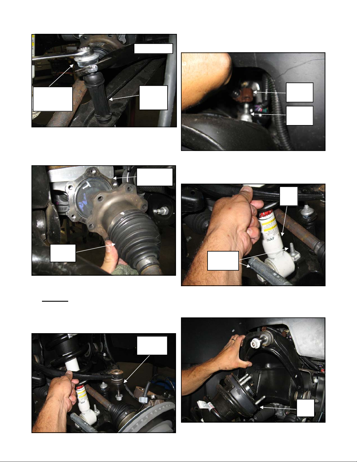
8. Remove the ABS line from the OE upper con-
trol arm. Leave bracket bolted to arm.
9. Using a flat blade screw driver carefully open
the upper control arm brake line retaining
bracket. Carefully, remove the rubber brake line
from the bracket. NOTE: Spraying the brake
line with lubricant will aid in it’s removal. Be
very careful to not damage the rubber line in
any way during it’s removal from the bracket.
OE Brake
Line Bracket
OE Control
Arm
OE Brake
Line
Spray
Lubricant
OE Skid Plate
4. Work on one side of the vehicle at a time.
5. Unclip the ABS line from the bracket on the
top of the control arm pocket. Unplug the
ABS wiring connector.
NOTE: Be careful not to damage the
ABS line during removal.
ABS Line
Clip
10. Remove the tie rod end nut. Using the proper
tool, carefully separate the outer tie rod end
from the OE knuckle.
OE Tie
Rod End
OE
Knuckle
11. Unbolt the sway bar end links from the sway
bar. Save the links and hardware for reinstallation.
4
Page 5
OE Sway Bar
TM102N
Revised
2.4.14
15. Remove the clips that hold the ABS wire to
the upper strut mounting studs.
OE Sway Bar
End Link
Hardware
OE Sway
Bar End
Link
12. Unbolt the OE CV axle from the differential.
Rest the CV axle on the lower control arm.
NOTE: Be very careful not to overextend
the CV axle during removal.
Differential
Flange
OE
CV Axle
OE Wire
Clip
OE Strut
Studs
16. Support the lower control arm with a jack and
unbolt the lower strut mounting bolts from the
lower control arm mount.
OE
Strut
OE Strut
Hardware
13. Using the proper tool carefully separate the
upper ball joint from the knuckle. Loosen but
DO NOT remove the retaining nut from the
upper ball joint.
14. Unbolt the previously loosened upper ball
joint retaining nut.
OE Upper
Ball Joint
17. Unbolt the nuts on the upper strut mounting
studs. Carefully remove the strut from the vehicle.
OE
Strut
5
Page 6

TM102N
Revised
2.4.14
18. Unbolt the upper control arm cam bolts and
remove the upper control arm from the vehicle. Save the cam bolts for reinstallation.
OE Upper
Control Arm
19. Unplug the 4WD control module wiring harness clip and vent tube secure up out of the
work area.
21. Remove the OE rear crossmember support
brace from the vehicle. Save the OE hardware for reinstallation.
OE Rear Crossmember
Support Brace
22. Support the differential with a jack and unbolt
the driver and passenger side mounts (2 per
side). Carefully remove the differential from
the vehicle.
OE Differential
OE 4WD Control Module
OE Wiring
Clip
20. Unbolt the front driveshaft from the differential and secure it out of the way of the work
area. Save the hardware for reuse.
OE
Driveshaft
23. Referring to the following picture, scribe a
mark on the driver side fin portion of the front
differential. This fin area will need to be
trimmed to provide adequate clearance once
the differential is reinstalled.
Area of
Differential
to Be
Trimmed
6
Page 7

24. Using a suitable cutting tool, (abrasive cutoff
wheel, Sawz-all, etc.), carefully trim off the
marked fin area. Do not cut into the housing.
Remove Fin Only!
NOTE: The thicker part of the spacer will
be orientated toward the front of the vehicle.
Front of Vehicle
90-4518
Drvr
Diff
Drop
OE Drvr Diff Mount
TM102N
Revised
2.4.14
Cutting
Tool
Area of
Differential
to Be
Trimmed
25. On the passenger side, the OE bolts need to be
removed from the pass side differential
bracket. Remove the bolts using an air hammer.
NOTE: If you do not have an air hammer
the bracket will need to be removed the vehicle so the bolts can be removed.
OE
Bolts
OE Pass
Diff
Mount
12mm X
35mm Bolt
12mm X
45mm Bolt
2. Install the passenger side differential drop
(90-4519) to the OE differential mount using
the supplied (1 front) 12mm X 80mm Allen
head bolt, (1 rear) 12mm X 70mm Allen
head bolt and (2) 12mm serrated nuts. Be
sure to use thread locker on these bolts.
Torque to 55 ft./lbs.
NOTE: The thicker part of the spacer will
be orientated toward the front of the vehicle.
Front of Vehicle
90-4519
Pass
Diff
Drop
12mm Serrated Nut
Air
Hammer
Install Front Suspension
1. Install the driver side differential drop (90-
4518) to the OE differential mount using the
supplied (1 front) 12mm X 45mm Allen
head bolt, (1 rear) 12mm X 35mm Allen
head bolt and hardware. Be sure to use
thread locker on these bolts. Torque to 55 ft./
lbs.
12mm X
70mm Bolt
12mm X 80mm Bolt
3. Using a jack, carefully raise the differential
into place and secure to the previously installed driver side drop bracket (90-4518) using the (2) supplied 12mm X 35mm and (2)
12mm lock washers, flat washers and hardware. Be sure to use thread locker on these
bolts. Torque to 55 ft./lbs.
7
OE Pass
Diff
Mount
Page 8

90-4518
Drvr
Diff
Drop
OE Diff
12mm X
35mm
Bolt
TM102N
Revised
2.4.14
6. Reinstall the front driveshaft to the front dif-
ferential using the previously removed OE
hardware. Be sure to use thread locker on
these bolts. Torque the OE bolts to 35 ft./lbs.
OE Driveshaft
4. Secure the differential to the previously in-
stalled passenger side drop bracket (90-4519)
using the (2) supplied 12mm X 35mm, (2)
12mm lock washers and (2) 12mm fender
washers and hardware. Be sure to use thread
locker on these bolts. Torque to 55 ft./lbs.
90-4519
Pass
Diff
Drop
OE Diff
(2)12mm
X 35mm
Bolt
5. Check clearance between the trimmed area of
the differential fin and the lower control arm
mounting pocket. If needed, remove more
material until adequate clearance is achieved.
Check
Differential
Fin
Clearance
Lower
Control
Arm
Pocket
OE Bolts
7. Reattach the 4WD control module wiring harness clip and vent tube to the differential.
8. Re-install the OE rear crossmember support
brace into the frame mounting pockets using
the previously removed OE hardware. Be
sure to use thread locker on these bolts.
Torque to 55 ft./lbs.
OE Bolts
OE Rear Crossmember
Support Brace
9. Install the supplied Zerk fitting into the new
upper control arm (82-8274 drvr and 82-8277
pass). Be very careful not to cross-thread or
over tighten the fitting.
10. Install the new upper control arm (82-8274
drvr and 82-8277 pass) into the OE mounting
pockets using the previously removed OE
cam bolts. Rotate the cams so they are all the
8
Page 9

TM102N
Revised
2.4.14
way out. Doing this will ensure the ball joint
is out as far out as possible. Torque the cam
bolt hardware to 95 ft./lbs.
82-8274 Drvr and 82-8277
Pass Upper Control Arm
11. Install the OE nuts onto the OE strut upper
studs. Using a suitable cutting tool, (abrasive
cutoff wheel, Sawz-all, etc.), carefully cut off
the top nipple part of the studs. Once the
studs have been cut, remove the OE nuts.
NOTE: Take care to not cut into the
threads of the studs.
Cutting Tool OE Strut Upper
Mounting Studs
82-8272
Strut
Spacer
OE Nuts
OE Strut
13. Remove the OE lower strut mounting clips
from the strut.
14. Fit the OE strut into the stock mounting locations. Fasten using the supplied (3 per side)
7/16” hardware on the top from hardware
pack (90-6317). Torque to 35 ft./lbs.
NOTE: Be sure that the locating tab on
the top ring of the strut spacer is facing toward the outside of the vehicle.
IMPORTANT!: Be sure the OE wiring
harness clips are reinstalled to the strut spacer
studs. Failure to do so may result in the wiring
harnesses being damaged by the steering column.
Nipple Area To
Be Trimmed
12. Attach the strut spacer (82-8272) to the top of
the strut using the OE hardware. Be sure to
use thread locker and torque to manufacturers
specifications.
7/16”
Nuts and
Washers
Strut
Assembly
15. Secure the OE lower strut cross pin to the
9
Page 10

TM102N
Revised
2.4.14
lower A-arm using the supplied (2 per side)
10mm X 55mm bolts and hardware. Torque
the bolts to 45 ft./lbs.
OE
Lower Strut
Mount
OE
Lower
A-Arm
10mm X
55mm Bolts
16. Reinstall the OE CV axle to the differential
using the previously removed OE bolts. Be
sure to apply thread locker to the bolts. Leave
the bolts loose at this time
18. Torque the OE CV bolts to 45 ft./lbs.
19. Reconnect the ABS wiring clips. Secure the
brake lines to the tab on the upper control arm.
Secure the ABS line using the smaller Adel
clamp (90-3240), the rubber brake line using the
larger Adel clamp (90-4554) and the 1/4”-20 X
3/4” bolt and hardware.
IMPORTANT!: The ABS line must be
routed under the control arm to avoid contact
with the wheel. Be sure to secure the brake
line and ABS line away from any moving parts.
Be sure that the lines do not rub or contact
anything.
90-3240 Adel
Clamp Small
1/4”-20 X
3/4” Bolt
OE CV Shaft Bolts
OE
CV Axle
17. Install the new upper control arm ball joint
into the OE knuckle. Start the supplied castle
nut. Torque to 40 ft./lbs. and install a new
supplied cotter pin.
NOTE: Using a pry bar to gain leverage
will aid in installation.
IMPORTANT!: If the new cotter pin cannot be installed due to hole alignment, DO
NOT loosen the castle nut. Tighten the castle nut until the holes are properly aligned.
OE ABS
Line
Upper
Control
Arm
Tab
20. On both sides of the vehicle, check the routing
of the brake lines and the ABS wire harnesses.
There must be no pinching, rubbing, or
stretching of either component. Use zip ties to
secure these items to the steering components.
At full droop, cycle the steering from lock to
lock while observing the reaction of these
components. Reposition them if needed.
21. Reinstall the tie rod end stud to the knuckle
and torque to 95 ft./lbs. Be sure to clean the
threads and use thread locking compound on
the tie rod end OE nut.
22. Install the previously removed OE sway bar
end links into their original location and secure using the previously removed OE hardware.
10
90-4544
Adel
Clamp
Large
OE
Brake
Line
Page 11

TM102N
Revised
2.4.14
OE Sway
Bar
OE Sway Bar
End Link
Hardware
OE Sway
Bar End
Link
OE Lower
Control arm
23. Be sure to use thread locker and torque the
sway bar hardware according to manufacturers specifications.
24. Repeat steps on the remaining side of the vehicle.
25. Install the new skid plate (82-9144) to the
front and rear crossmember using the (3)
10mm X 30mm bolts and hardware. Be sure
to use thread locker and torque to 45 ft./lbs.
28. Recheck all hardware for proper installation
and torque at this time.
IMPORTANT! BE SURE TO BRING
THE VEHICLE IMMEDIATELY TO A REPUTABLE ALIGNMENT SHOP TO BE
ALIGNED!
OE Skid
Plate Bolt
82-9144
Lower Skid
Plate
OE Skid Plate Bolt
26. Grease the upper control arm ball joints.
NOTE: It’s a good idea to grease the ball
joints every time you change the oil.
27. Install the front wheels and lower the vehicle
to the ground. Torque the lug nuts according
to the wheel manufacturers recommendations.
11
Page 12

TM102N
Revised
2.4.14
Prepare to Install Rear
Suspension
1. Block the front tires and raise the rear of the
vehicle. Support the frame with jack stands
forward of the rear springs.
2. Remove the rear wheels.
3. Unclip the ABS line from the frame rails.
Remove the plastic clip and discard.
4. Carefully remove the OE shock absorbers. It
may be necessary to raise the differential
housing slightly to facilitate their removal.
OE Brake
Line Bracket
5/16” X
1” Bolt
OE
Bolt
90-3341
Brake Line
Relocation
bracket
Install Rear Suspension
9. Install the lift block (95-300C) making sure
the pin are fitted into the hole on the spring
perch. Use your floor jack to raise the axle to
the spring making sure the pin on the leaf
spring fit into the holes on the new lift block.
13-90086
U-Bolt
95-300C
Lift Block
Hi Nut Pack
20-65302
10. Install the new U- bolts (13-90086) over the
leaf spring assembly and using the new washers and nuts (20-65302) supplied along with
the existing spring plates.
Rear End
5. Unbolt the rear brake line bracket from the
tab on the rear end.
6. Install the rear brake line relocation bracket
(90-3341) to the rear end using the previously
removed OE bolt. Secure the rear brake line
to the new relocation bracket (90-3341) using
the supplied 5/16” X 1” bolt and hardware.
7. Work on one side of the vehicle at a time.
8. Support the rear axle with a floor jack and
remove the U-bolts on the driver side.
Loosen the U-bolts on the passenger side and
carefully lower the rear axle.
NOTE: Be sure not to over extend the
rear brake line and rear axle vent line.
11. Use the zip ties from pack (90-6319) and secure the ABS line to the OE bump stop
bracket.
12. Repeat the installation on the other side of the
vehicle.
13. When the installation of the remaining side is
complete, torque the U-bolts to 120 ft./lbs.
NOTE: You may trim the excess threads
off of the newly installed U-bolts.
14. Install the new Trail Master shocks
(TM75800W) using the previously removed
OE bolts. Be sure to use thread locker and
torque the hardware to 85 ft./lbs.
15. Check for adequate clearance on all repositioned brake lines and emergency brake cables. Make sure you check with the suspension fully extended, and compressed.
12
Page 13

TM102N
Revised
2.4.14
14. Reinstall the wheels and lower the vehicle to the
ground. Torque the lug nuts according to the wheel
manufacturers recommendations.
15. After installation is complete, double check that all
nuts and bolts are tight. Refer to the chart at the
end of this document for torque specifications.
(Do not retighten nuts and bolts where thread locking compound was used).
Dynamic Vehicle Check
1. Check steering and suspension in all positions
to ensure that there is no bind and adequate
clearance between all moving, fixed, and
heated members. Check operation of clutch,
brake system, and parking brake. Check operation of transmission and transfer case. Ensure there is full engagement in all gears and
4WD ranges. Check battery connections and
electrical component operations. Test-drive
vehicle.
NOTE
All warranty information, instruction sheets, and
other documents regarding the installation of this
product must be retained by the vehicle owner.
Information contained in the instructions and on
the warranty card will be required for any warranty
claims. The vehicle owner needs to understand
the modifications made to the vehicle and how
they affect vehicle handling and performance.
Failure to provide the customer with this information can result in damage to the vehicle and severe personal injury.
NOTES:
On completion of the installation, have the
suspension and headlights re-aligned.
After 100 miles recheck for proper torque on
all newly installed hardware.
Recheck all hardware for tightness after off
road use.
WARNING
Re-torque all fasteners after 500 miles and after
off road use. All suspension lift components
should be visually inspected and fasteners retorqued during routine vehicle servicing.
Caution:
Larger wheel and tire combinations increase
stress and wear on steering and suspension
components, which leads to increased maintenance and higher risk for component failure. Larger wheel and tire combinations also alter speedometer calibration, braking effectiveness, center
of gravity, and handling characteristics. Consult
an experienced local off road shop to find what
wheel and tire combinations work best with your
vehicle.
13
Page 14

TM102N
Revised
2.4.14
Kit Parts List:
Box TM102N-1
82-8272 STRUT SPACER 2
82-9144 LOWER SKID PLATE 1
90-4518 DIFF MOUNT: Drvr– 4WD only 1
90-4519 DIFF MOUNT: Pass– 4WD only 1
82-8274 UPPER CONTROL ARM: Drvr 1
82-8277 UPPER CONTROL ARM: Pass 1
95-300C CAST IRON LIFT BLOCK 2
13-90086 U-BOLT: 9/16” X 2.650” X 11.50” 4
20-65302 HARDWARE PACK: Rear U-Bolts 1
13-30330 9/16” FLAT WASHER 8
13-10423 9/16” HIGH NUT 8
90-3341 REAR BRAKE LINE RELOCATION BRACKET 1
90-6299 HARDWARE PACK: Rear Brake Line 1
5/16” X 1” HEX BOLT Gr. 8 1
5/16” FLAT WASHER 2
5/16” NYLOCK NUT 1
90-6899 HARDWARE PACK: Diff Mount Drvr – 4WD only 1
10mm X 30mm HEX BOLT 3
12mm-1.75 X 35mm ALLEN HEAD BOLT 1
12mm-1.75 X 45mm ALLEN HEAD BOLT 1
12mm-1.75 X 70mm ALLEN HEAD BOLT 1
12mm-1.75 X 80mm ALLEN HEAD BOLT 1
12mm SERRATED FLANGE NUT 2
12mm X 35mm HEX BOLT 4
12mm FLAT WASHER 2
12mm FENDER WASHER 2
12mm SPLIT-LOCK WASHER 4
90-6900 HARDWARE PACK: Diff Mount Drvr – 4WD only 1
10mm X 55mm HEX BOLT 4
10mm STOVER NUT 4
10mm FLAT WASHER 8
14
Page 15

TM102N
Revised
2.4.14
90-4544 ADEL CLAMP: Large: Front Brake Line 2
90-3240 ADEL CLAMP: Small: Front ABS Line 2
90-6902 HARDWARE PACK:
ABS Line 1
25C75HCS8Y 1/4”-20 X 3/4” HEX BOLT Gr. 8 2
25NWHDY/SAE 1/4” HARDENED FLAT WASHER 4
25CNNE8Y 1/4”-20 NYLOCK NUT Gr. 8 2
90-6317 HARDWARE PACK:
Strut Spacer 1
72-043200810 7/16”-20 HEX NUT Gr. 8 6
73-04300830 7/16” SAE FLAT WASHER 6
73-04300836 7/16” SPLIT LOCK WASHER 6
90-6623 HARDWARE PACK: Upper Ball Joint Cotter Pin 1
15N200PCOZ 5/32” x 2” COTTER PIN 4
12N150PCOZ 1/8” X 1 1/2” COTTER PIN 4
90-6319 HARDWARE PACK: Zip Ties 1
10999 ZIP TIE, 11", BLACK 12
TM75800W REAR SHOCKS 2
15
Page 16

TM102N
Revised
2.4.14
Notice to Owner Operator, Dealer and Installer:
Vehicles that have been enhanced for off-road performance often have unique handling characteristics
due to the higher center of gravity and larger tires. This vehicle may handle, react and stop differently than
many passenger cars or unmodified vehicles, both on and off–road. You must drive your vehicle safely!
Extreme care should always be taken to prevent vehicle rollover or loss of control, which can result in serious injury or even death. Always avoid sudden sharp turns or abrupt maneuvers and allow more time and
distance for braking! Trail Master Suspension
reminds you to fasten your seat belts at all times and reduce speed! We will gladly answer any questions concerning the design, function, maintenance and correct use of our products.
Please make sure your Dealer/Installer explains and delivers all warning notices, warranty forms
and instruction sheets included with Trail Master Suspension
product.
Application listings in this catalog have been carefully fit checked for each model and year denoted. However, Trail Master Suspension
reserves the right to update as necessary, without notice, and will not be
held responsible for misprints, changes or variations made by vehicle manufacturers. Please call when in
question regarding new model year, vehicles not listed by specific body or chassis styles or vehicles not
originally distributed in the USA.
Please note that certain mechanical aspects of any suspension lift product may accelerate ordinary wear of original equipment components. Further, installation of certain Trail Master Suspension
products may void the vehicle’s factory warranty as it pertains to certain covered parts; it is the consumer’s responsibility to check with their local dealer for warranty coverage before installation of the lift.
Warranty and Return policy:
Trail Master Suspension
materials. Trail Master Suspension’s
Trail Master Suspension’s
warranties its full line of products to be free from defects in workmanship and
obligation under this warranty is limited to repair or replacement, at
option, of the defective product. Any and all costs of removal, installation,
freight or incidental or consequential damages are expressly excluded from this warranty. Trail Master
Suspension is not responsible for damages and / or warranty of other vehicle parts related or non-related
to the installation of Trail Master Suspension
product. A consumer who makes the decision to modify his
vehicle with aftermarket components of any kind will assume all risk and responsibility for potential damages incurred as a result of their chosen modifications. Warranty coverage does not include consumer
opinions regarding ride comfort, fitment and design. Warranty claims can be made directly with Trail Mas-
ter Suspension or at any factory authorized Trail Master Suspension dealer.
IMPORTANT! To validate the warranty on this purchase please be sure to mail in the warranty card.
Claims not covered under warranty-
• Parts subject to normal wear; this includes bushings, bump stops, ball joints, tie rod ends and heim joints
• Discontinued products at Trail Master Suspension’s
discretion
• Bent or dented product
• Finish after 90 days
• Leaf or coil springs used without proper bump stops
• Products with evident damage caused by abrasion or contact with other items
• Damage caused as a result of not following recommendations or requirements called out in the installation manuals
• Products used in applications other than listed in Trail Master Suspension’s
catalog
• Components or accessories used in conjunction with other manufacturer’s systems
• Warranty claims without “Proof of Purchase”
• Trail Master Suspension
accepts no responsibility for any altered product, improper installation, lack of
or improper maintenance, or improper use of our products.
E-Mail: info@trailmastersuspension.com
Website: www.trailmastersuspension.com
Ph: (877) 695-7812
16
 Loading...