

Page 1
er’
User Manual
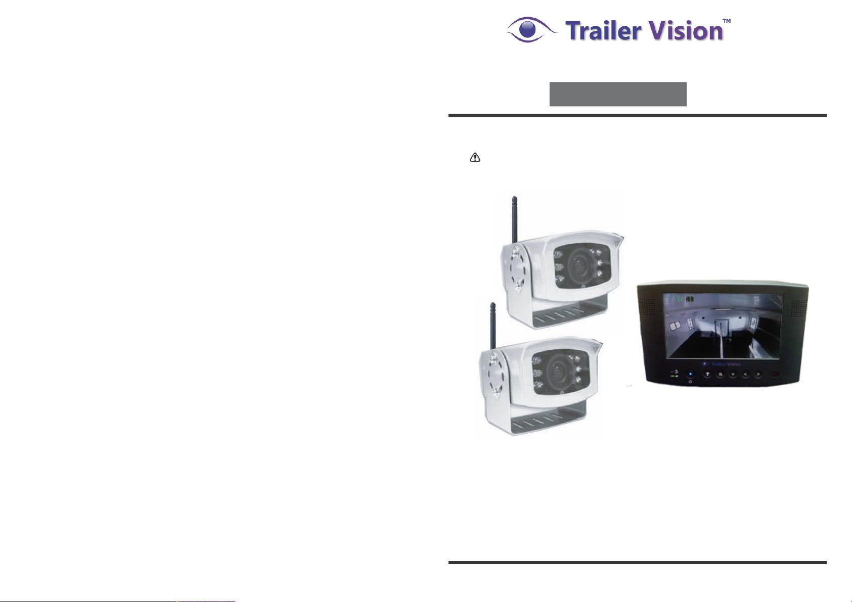
Model: Digi-Max
Digital Wireless
Camera System
This is a driving aid, safe driving, good observation and
use of the rear-view/wing mirror are still necessary.
PLEASE READ CAREFULLY AND SAVE
This manual contains important information about this product's operation.
If you are installing this product for others, you must leave this manual,
or a copy, with the end user.
Page 2
1
System Parts
Contents
Digi-Max
Safety Precaution and Hazard Notice / FCC Warning / Disposal
The System Parts
Getting Started
Step 1: System Connections
Step 2: Basic Operation
Monitor Function Buttons and Indicators
View Mode
Step 3: Advanced Operation
The Menu
Skip Certain Camera During Manual Scan
Setting QUAD Display
Pairing a Camera
System Setup and Reset
Trouble Shooting
Trouble Shooting Table
Product Specification
System Parts
(1) Digital Wireless IP65 Colour Camera
(2) 7" LCD Colour Monitor
(3) Antenna for the camera
(4) 5V Cigarette Power Adapter for the Monitor
(5) Screw/fixings bag
(6) Windscreen holder for the Monitor
(7) Dash-board mount for the Monitor
(8) IR Remote Control for the Monitor
(9) User Manual
Page 3
17
2
U
Camera
Monitor
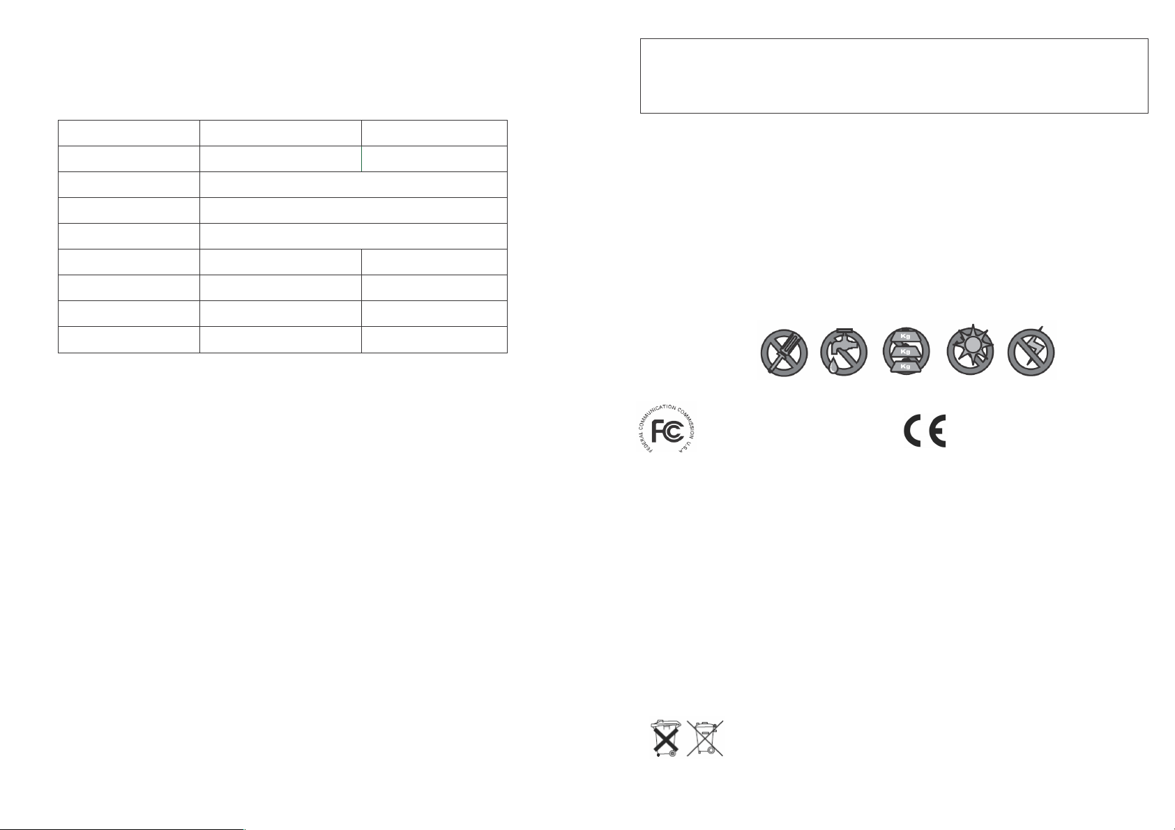
Maximum Channels
1
4
Communication Range
200 metres in open space
Resolution
640 × 480 (VGA)
Operating Temperature
-10˚C + 50˚C
Operating Voltage
DC 12V~24V
DC 5V
Current Consumption
160mA(max)
850mA(max)
Night View Range
3~5 M
Dimension
95 × 92 × 80 mm
233 × 145 × 36 mm
ser’
Product Specification
WELCOME
Dear Customer,
Thank you for purchasing this unique product, which utilises the latest digital wireless technology ensuring ZERO
interference. Please read the following information carefully before installing and using this product.
Important Safety Precautions
Damage caused by non-compliance with this operating manual will void the warranty! We will not assume any liability
for
dam ag
e to items or persons caused by improper handling or non-compliance with the safety notices! Any warranty
claim will be null and void in such cases.
1. Do not drop, puncture or disassemble the camera or monitor; otherwise the warranty will be void.
2. Avoid all contact with water, and dry hands before using the monitor.
3. Never tug on the power cords.
4. Do not expose the monitor to high temperature, or leave it positioned in direct sunlight (e.g. permanently fixed to the
windscreen). Doing so may cause damage, or temporary malfunction.
5. Use the devices with care; only gentle pressure is required to use the monitor buttons.
6. For your own safety, avoid using the camera or power off the camera when there is a storm or lightning.
7. Remove the monitor power adapter during long periods between use.
8. Use only the accessories and power adapters supplied by the manufacturer.
9. To meet the regulations pertaining to parental
res ponsi bilit
y, keep the devices out of the reach of infants.
10. Ensure that power cables do not get crushed or damaged by sharp edges.
FCC Co mpliance State ment: This de vice complies with
Part 15 of the FCC R ules. Operation is s ubjected to t he
following two c onditions: (1) t his devi ce may not cause
harmful i nterference, a nd (2) this dev ice must acc ept
any inte rference recei ved, including interference that
may ca use undesire d operation.
Products with CE Ma rking c omply with E MC Directive
(2004/10 8/EC); Low Voltage Dire ctive (73/23/E EC);
R&TTE (1999/5/EC) i ssued by the Commission of the
Europe an Community. C ompliance wit h these directives
implies c onformity to th e following E uropean No rms:
EMC: EN 301 489
LVD: EN 60 950
Radio: EN 300 328
FCC/CE WARNING
This eq uipment has b een tested an d found to com ply wit h limits for a Class B digit al device, pu rsuant to Par t 15 of the FCC rules and ETSI (EN)
300328. These limits are designed t o provide re asonable pr otection against harmful interfe rence in resid ential installa tions. This eq uipment
generate s, uses, and can radiate radio frequen cy energy, and if not installed and used in acco rdance wit h the inst ructions, ma y cause har mful
interfere nce to r adio commu nications. H owever, there is no guarantee that interfer ence will not occur in a particular i nstallation. I f this equipment
does ca use interferen ce to radio o r television e quipment re ception, which can be determined by turning t he equipment off and on, the use r is
encoura ged to t ry to correct the interfere nce by one o r more
of the foll owing measu res:-Reorient or reloc ate the recei ving antenn a.-Move the eq uipment awa y from the monitor.-Plug th e equipmen t into an outl et
on a cir cuit different fr om that to wh ich the monit or is connect ed.-Consult t he dealer or an experienc ed radio/televi sion technici an for addition al
suggesti ons. You are cautio ned that any change or modifications to the equip ment not expr essly approved by the party resp onsible for c ompliance
could voi d your auth ority to operat e such equip ment.
Disposa l
If the c amera syste m no longer fu nctions or ca n no longer be repaired, it must be disp osed of acco rding to the valid statutor y regulations . Disposal of
spent b atteries / acc umulators:
You are requi red by law (B attery O rdinance) to ret urn all spen t batteries a nd accumulat ors. Disposin g of spent
batteries/ accumulators w ith common household w aste is prohibi ted! Batterie s/accumulators that co ntain hazard ous
substan ces are marke d with the sy mbols on the side. These symbols indica te that it is pro hibited to disp ose of
these b atteries/ accu mulators in t he househol d waste. The a bbreviations f or the respec tive heavy m etals are: Cd =
cadmiu m,
Hg= merc ury, Pb= le ad. You can retu rn spent batteri es and accumul ators that can no lo nger be c harged to the
designa ted collecti on points in your comm unity, o utlets or wh erever batt eries or ac cumulators are sold. Following th ese
instructi ons will allow y ou to fulfil th e legal requi rements and c ontribute to th e protection of our environ ment!
Page 4
3
16
USB
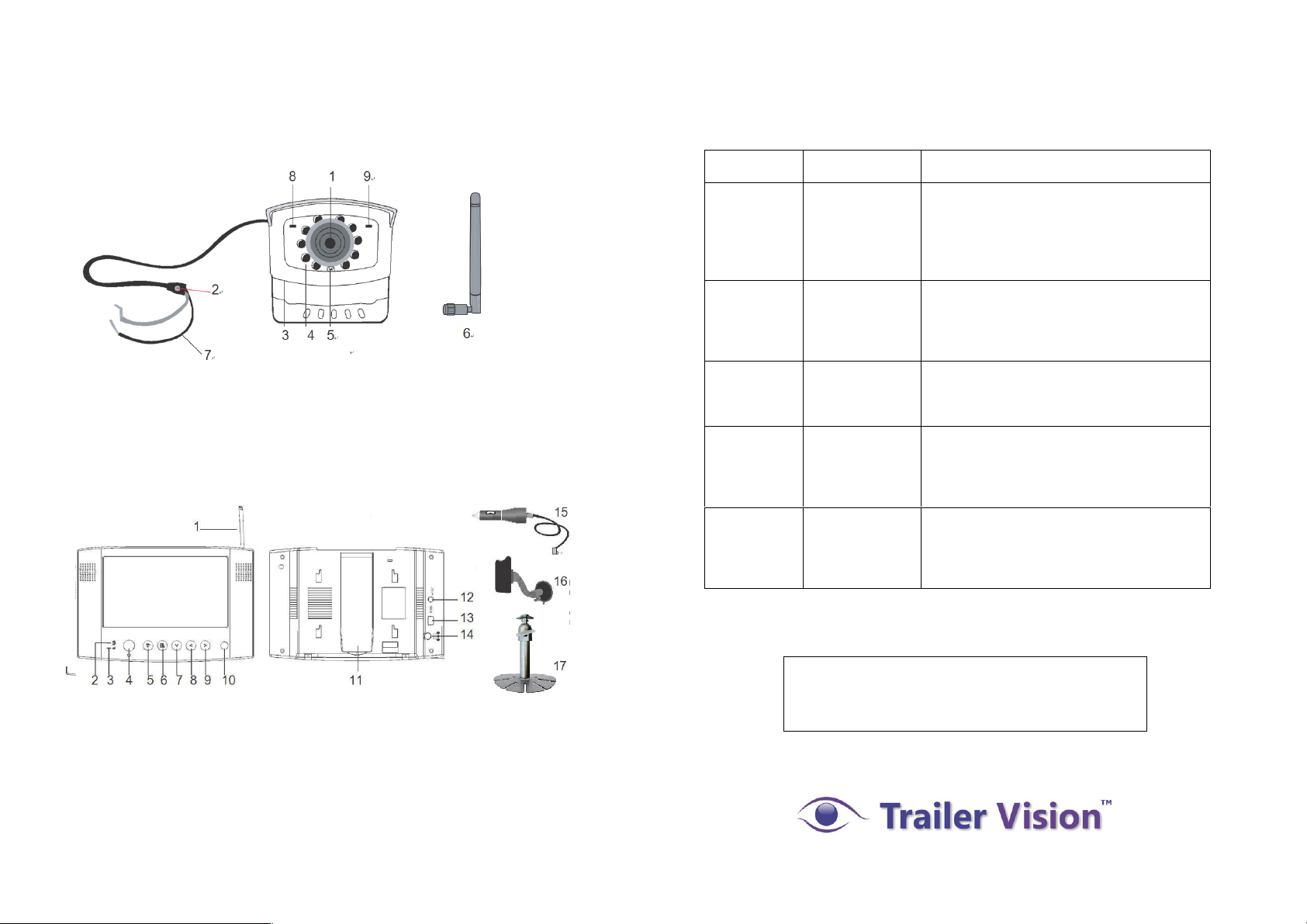
The System Parts
Wireless Camera
Trouble Shooting Table
Before requesting service, please complete the checks detailed below.
If you are in doubt about any of the following, or if the solutions
described in the chart do not solve the problem, please contact us.
1. Camera Lens
2. Pairing Key (cover/sealed)
3. Mounting Bracket
4. IR LED (Night Vision)
5. EDS (light sensor)
6. Antenna
7. Power Cord
8. Link/Pair LED Indicator
9. Power LED Indicator
7" LCD Wireless Monitor
1
15
12
13
14
16
2 3 4 5 6 7 8 9 10 11
1. Antenna
2. Pairing Indicator
3. Signal Indicator
4. Power On/Off
5. Change Channel/Pair Camera
6. Menu Selection
7. Cursor Down
8. Cursor Left
9. Cursor Right
10. IR Sensor
11. Back Flip Stand
12. A/V Out
13. USB Out (none functional)
14. DC In
15. Cigarette Power Adaptor
16. Windscreen Holder
17. Dashboard Mount
Problem
Possible
Cause
Remedy
System
Message
shows “No
Signal” on
the monitor
screen.
No power
supply to
corresponding
camera(s).
Check that the reversing light (if the camera
is powered from the reversing light) is
working. Check the camera wiring, ensure
the polarities are correctly connected and
12-24V is available.
Low signal,
or unstable
signal.
Channel is not
paired with
camera.
To complete Pairing, select reverse gear,
with the hand brake ON, then press the
camera pair button. See [Advanced
Operation - Pairing Camera] section as a
guide.
Low signal
or unstable
signal
Antenna
directional
limitation.
Adjust & secure camera antenna, position
camera & monitor antenna vertically.
Powerful
tr ansmitter /
ra dio signal in
vicinity of
monitor/camera.
Relocate source of radio signal, or
reposition the camera/monitor.
Dim / over
bright image
on monitor
screen.
Monitor
brightness
incorrectly
adjusted.
Press [OK] button, select menu, enter
[System Setup]; adjust [Brightness].
See [Advance Operation – System Setup]
for detail.
For technical support please email:
Page 5
4
15
Trouble Shooting
This section offers some helpful information to overcome most of the problems that you may
encounter. We also hope that this section assists you to achieve a quick and easy
installation/setup.
Problem Diagnosis
This innovative digital wireless solution integrates advance Frequency Hopping Spread
Spectrum (FHSS) technology. This technology greatly reduces the interference that comes
from other devic es using the same radio frequency (2.4GHz), e.g. WIFI, Bluetooth, cordless
phones etc. You now can enjoy superior wireless picture quality without a flickering or noisy
image. However, weaker signal (lag or still image) may be observed from time to time,
depending on th e environment where the system is installed.
The system complies with FCC part 15.247, ETSI (EN) 300 328, audio/video signals transmitted
about, or over 500 feet / 150 metre in the ‘line of sight’. However, ‘line of sight’ installation is
difficult to achieve due to obstacles etc. Factors affecting transmission include microwave ovens
and/or other high frequency electromagnetic waves. Reinforced concrete walls, large-scale metal
products and objects should not be located near to the camera, or the monitor. Water also creates
an obstacle to signal transmission, as it absorbs the signal and should be avoided. People etc
passing through the transmission area may also cause unstable signal quality. Howeve r, in ‘normal
use’ as a rear-view or interior (vehicle) camera, the system should offer excellent performance and
provide a clear and interference-free image/view.
How to improve the wireless signal quality?
If possible, remove any obstacles from between the camera and monitor that might reflect/absorb
the signal. Obstacles could include furniture, cabinets or walls. If the wireless signal strength is low,
position the monitor/antenna at a new angle (ideally vertically), or readjust camera/monitor position
until an improvement is achieved. Or, if possible, relocate the camera closer to the monitor.
Why Image Compression?
In order to achieve a secure and interference free signal, this digital wireless system utilises a
narrow 2Mb frequency-hopping bandwidth. Different from traditional 2.4GHz analogue wireless
systems, the digital wireless signal is compressed and then transmitted in Motion JPEG (MJPEG)
format. By digitising and compressing the raw analogue data the available bandwidth is used more
efficiently/securely. Consequentially, you might observe an indent image line if you are using a
larger display monitor, or a plasma TV.
How to improve the image quality when using large display screens?
When QVGA is selected, ‘pixel scattering’ is unavoidable. However, you can change the image to
VGA and by doing so, more pixels are ‘scattered’ on the screen. Therefore to achieve the best
display performance, when outputting the video/signal, a 32" or smaller monitor / TV is
recommended.
Getting Started
Step1: System Connections
Camera Connection:
3.
1.
2.
AB
-168
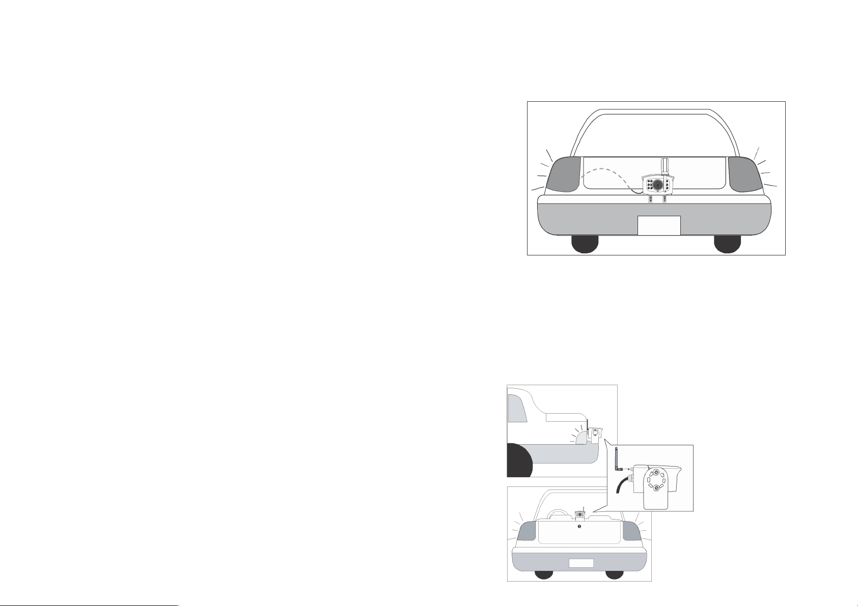
1. For reversing, choose a location on t he rear bumper etc that you wish to
install t he c ame ra (usually in the middle of bumper), for a HGV etc high up
and looking down, usu ally gi ves th e best view. For inside a horsebox/tr ailer,
mount the camera high up and ideally behind the horse(s).
2. Screw the camera's mounting bracket to the desired l ocation.
3. For reversing, connect the power cable to the reversing light of the vehicle
and th e ca mer a will be automatically powered when the vehicle is in reverse;
otherwise connect to any available power source (ideally use a switch ed
source to prevent inadvertent battery drain).
Antenna Installation to th e Camer a:
Screw the dipole antenna to the antenna
connector.
OR
AB
-168
Page 6
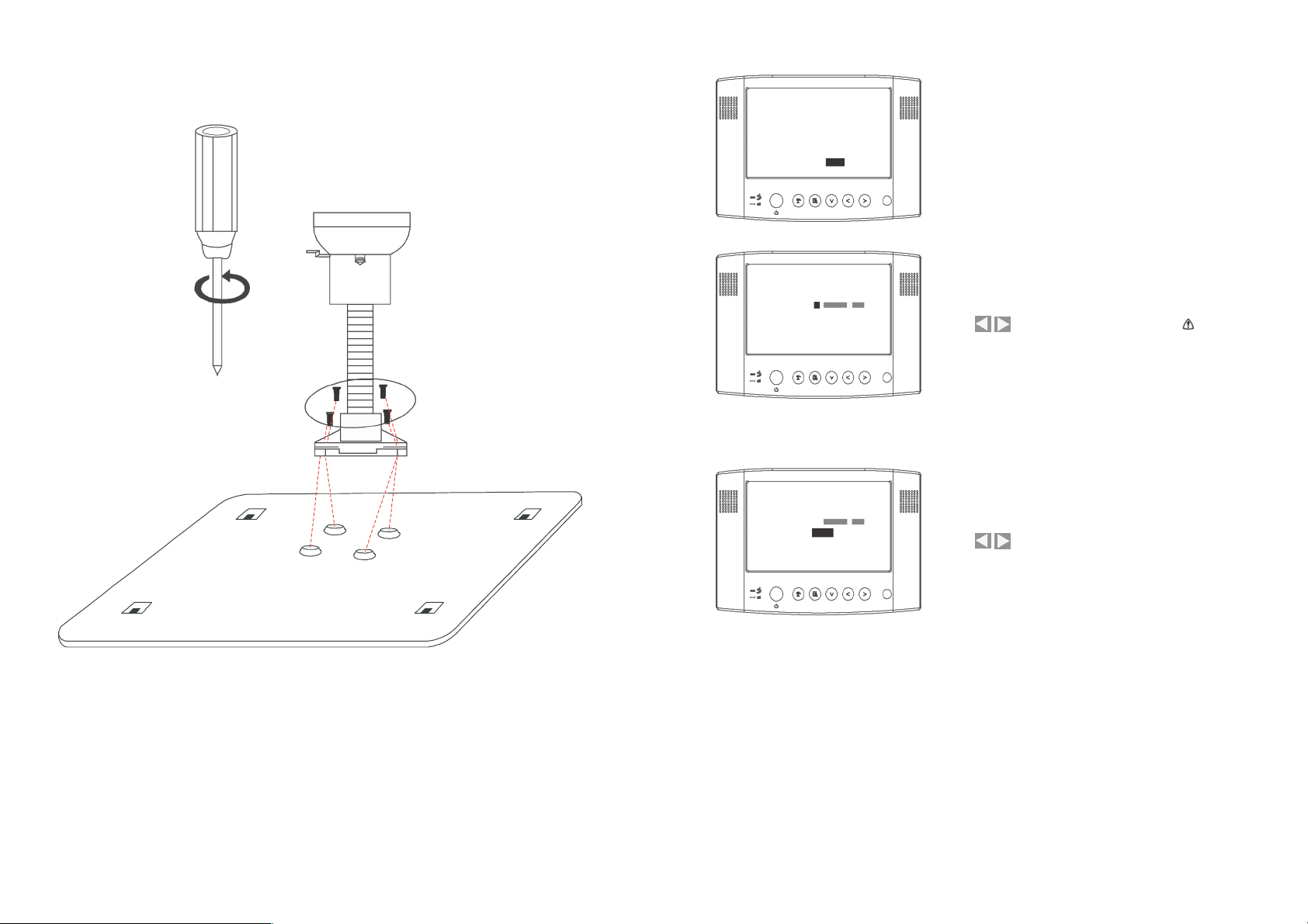
Windscreen Holder Installation Guide
System Setup and Reset
Resolution QVGA
QUAD OFF
CA M1 ON
CA M2 ON
CA M3 ON
CA M4 ON
Pair CAM 1 2 3 4
System
Set up
Factory
Res et
A. Select [System Setup], press [OK] to enter.
Brightness 8
0 15
Frequency 50 Hz
B. Use to adjust monitor brightness.
Brightness setting takes effect on LCD monitor
only.
Brightness 8
0 15
Frequency 50 Hz
B. Use to select the required frequency (for
the UK, please s et the frequ ency to 50Hz).
Fasten the screws to the metal panel as sh own above.
(Please use the dash-board mount for permanent fixture).
Page 7
6
13
S
B
S
B
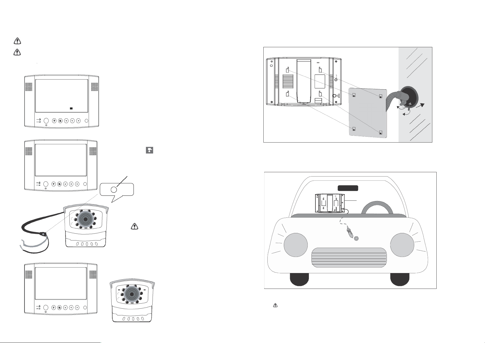
Pairing a Camera(s)
Proceed with this function ONLY when the camera cannot be found by the system or whe n you
have an additional/new camera(s) to view.
Before pairing the camera, make sure t ha t th e camera power cord is cor rec tly connected to a li ve
power sourc e & the blue LED is ill uminated.
LCD Monitor
Connection
Pair CAM 1 2 3 4
A. Simply pair the camera by selecting the
desired channel in Menu Mode.
B. Only assign one camera to one channel.
Channel memory will be overwritten if
2
another camera is assigned to t he same channel.
1
3
C. Pairing a new camera to channel 3, settings
as shown:
Please P ress
Pair Key
on Camera Side
D. Press (Pair).
E. System will count down within 60
seconds, system message as sh own:
Pairing key
1. Fasten the metal panel to th e m onitor.
2. Attach the rubber pad to the windscreen. Make sure the glass is clean and dry to ensure that the
holder fixes securely.
3. Pull the lock knob down to fix the holder (this holder is not designed to be left permanently in the
winds creen – please use the dashboard m ount for permanent fi xture).
F. Within th e 60-second
count down, press the
Link/Pairing Key on the
camera cabl e.
To complete Pairing, the camera needs to
be powered, which may mean that the
reverse gear will need to be selected
(without the engine running and with the
hand-brake applied).
DC Input
Cigarette Power
Source
G. Once pairing is
completed, the
camera and
monitor status
indicators will
illuminate.
4. Connect the cigarette adaptor to the DC power jack of the LCD monitor.
ONLY use the pro vi de d power adaptor (a hard-wire power adapter is available separately).
5. Plug the power unit to the cigarette power source (w hi ch ma y operate via the ignition)
.
6. Position the monitor antenna (& camera antenna) vertically to achieve the best reception.
Page 8
7
12
Step 2: Basic Operation
Setting QUAD Display
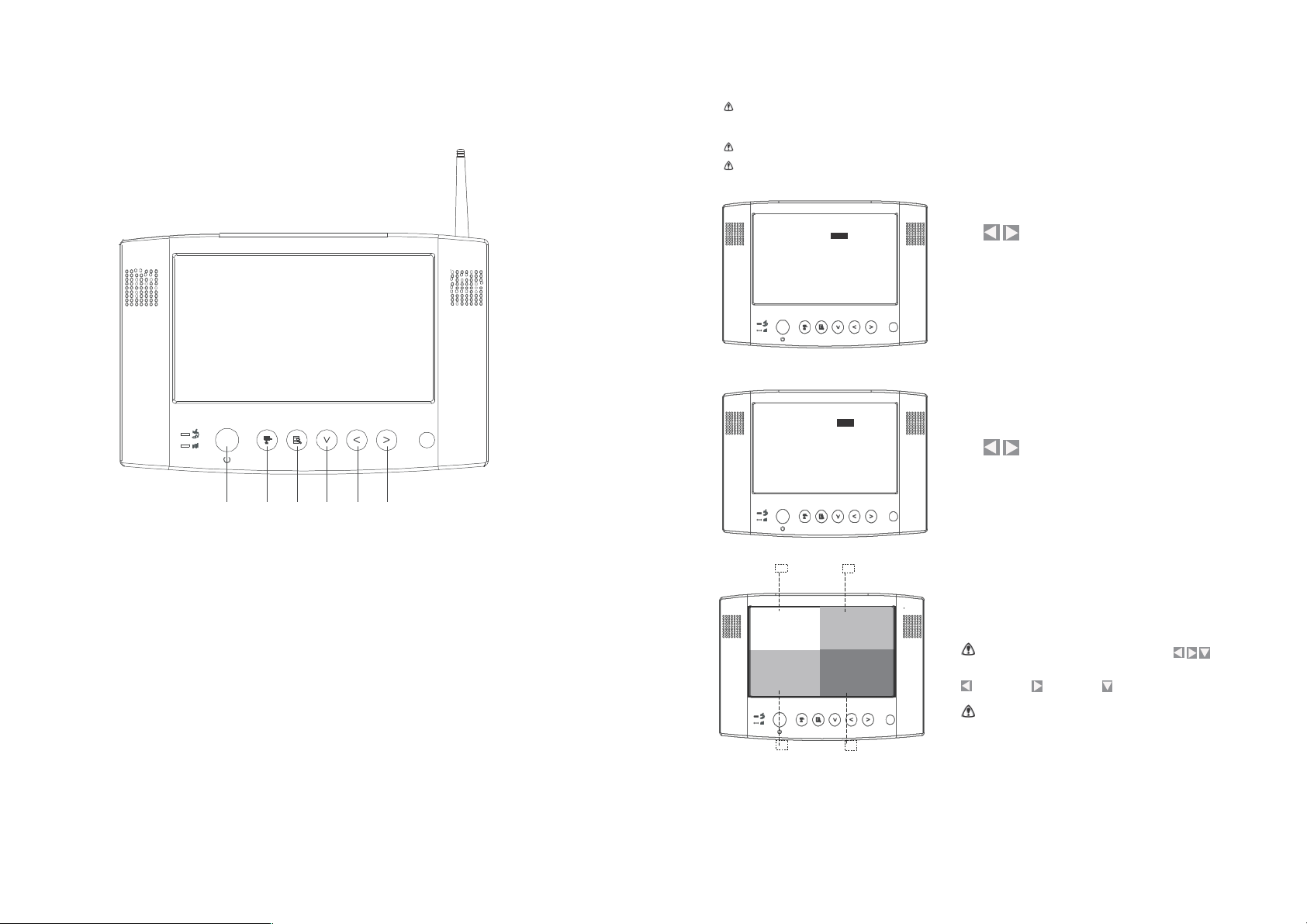
Monitor Function Buttons and Indicators
This function is available for multi cameras use. Before setting QUAD display, make sure all cameras are
paired to
assigned channels. See [Advance Operation – Pair Camera] section as a guide.
QUAD display will be restored to one camera display after pressing the directional keys for manual scan.
To ensu re correc t display, turn all available channels ON PRIOR to entering QUAD mode.
Re soluti on Q VGA
QUAD OFF
CA M1 ON
CA M2 O N
CA M3 O N
CAM 4 O N
Pair CAM 1 2 3 4
Syst em Set up
Fact ory Re set
A. Use to turn all available channels ON.
Re soluti on Q VGA
QUAD ON
CA M1 O N
CA M2 ON
CA M3 ON
CA M4 O N
Pai r CAM 1 2 3 4
System Setup
Factory Rese t
B. Use to turn QUAD Mode on.
1 2 3 4 5 6
1. [Power Button]
Press th e button to power ON, hold it down to swi tch power OFF. CH1 CH2
2. (View Mode) [Scan Channels] / (Menu Mode) [Pair Camera]
In View mode, manually scan available camera channels. In Pair
mode, assign and pair a camera to a specified channel.
3. (Menu Mode) [Menu / Enter Button]
4. (Menu Mode) [Cursor DOWN] / (QUAD View Mode)
5. (Menu Mode) [Cursor Left] / (QUAD View Mode)
C. QUAD display as shown. Unavailable channels will be
displayed as a blank screen.
To l eave QU AD display, simpl y
press to go
to a
specific
channel.
=
CAM 4
= CAM 3 = CAM 2
In
QU AD displ ay/ [Pa ir] functions are
not available.
6. (Menu Mode) [Cursor Right] / (QUAD View Mode)
CH3
CH4
Page 9
11
8
QVGA
Skip Certain Camera(s) During Manual Scan
Before setting Scan and Skip, make sure all cameras are paired to assigned
channels, see
next pages for
detail.
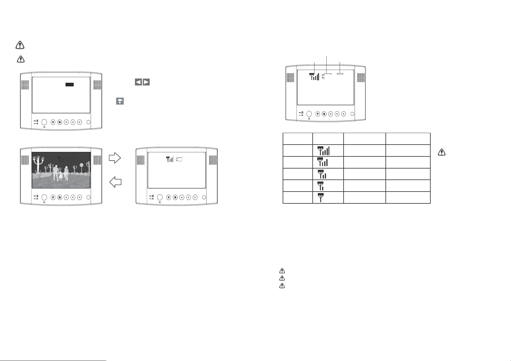
View Mode
Channel Indicator
Make sure the channel assigned to the reversing camera is turned ON.
Signal Indicator
Resolution Indicator
Resolutio n QVGA
QUAD
ON
C AM 1 ON
C AM 2 OF F
C AM 3 ON
C AM 4 OF F
Pair C AM 1 2 3 4
System Setup
Factory Rese t
A. Simply set the skip camera(s) OFF by
pressing (Left / Right).
B. To skip Camera 2 and 4 by pressing
(Cam), settings as shown:
Display as shown:
1 3
A. Signal Indicator shows signal strength, more bars indicate a stronger signal.
Signal Level Indicator VGA Frame Rate QVGA Frame Rate
Perfect 5~10Fps 15~30Fps
Good
3~5Fps 12~20Fps
Fair 2~4Fps 8~15Fps
Low 0~1Fps 0~4Fps
Zero 0Fps 0Fps
It’s recommended
that QVGA
resolution is utilised
to ens ure th at a
smooth image is
displayed. To do so,
simply select
[Res olution]
to switch to QVGA as
shown on the
[Resolution Indicator].
B. Reversing Camera Operation Steps:
1. Press [Power] button to power ON.
2. Switch to QVGA mode if necessary.
3. Select Reverse Gear (if the camera is powered by the reversing light).
4. Reverse image will be displayed.
5. If the/a camera is used to view the interior of a vehicle/horsebox, then it
should be powered from an ignition controlled circuit, or a lighting circuit could
be used.
STOP REVERSING when [NO Signal] shows on the monitor.
Press [Cam] button to locate the reversing camera channel if necessary.
This is a driving aid, safe driving, good observation and use of the rear-view/wing
mirror are still necessary.
1
Page 10

C. Channel indicator shows the current camera being displayed by the monitor.
By pressing (Cam), you can manually switch between cameras.
1
2
Step3: Advanced Operation
Knowing the Menu
By Pressing (Menu), you can enter / exit Menu Mode
You can Use (Left / Right / Down) to select and change the
settings.
Camera 1 Camera 2
3 4
Resoluti on QVGA
QUAD OFF
CAM1 ON
CAM2 ON
CAM3 ON
CAM4 ON
Pair CA M 1 2 3 4
System Setup
Factor y Reset
Camera 3 Camera 4
 Loading...