

Page 1
Page 2
1
The most advanced trailer dolly on the planet
Operating Manual
WARNING
Carefully read and understand all the instructions before
connecting your new Trailer Valet.
Failure to follow these guidelines may result in serious injury to
persons and property for which Trailer Valet will not be held liable.
Do not allow persons to operate or assemble this trailer dolly until
they have read this manual and have developed a thorough
understanding of how the trailer dolly works.
SAVE THESE INSTRUCTIONS
Page 3
2
Visit us at trailervalet.com/support for
use your Trailer Valet.
Congratulations on your purchase of the Trailer Valet. For your future reference please complete
the owner’s record below:
Purchase Date: ______________________Order No.:______________________
Retailer:_____________________________
Be sure to save your receipt and owner’s manual with warranty information in a safe place.
The Trailer Valet is made of high strength steel and given a powder coat finish made to resist
corrosion from the elements and marine use. When cared for properly, it will provide years of
service. The Trailer Valet mounts to the coupler of the trailer tongue with the aid of our specially
designed Ball Attachment. Once attached to your trailer, the Trailer Valet makes maneuvering your
trailer much easier. Hitching, unhitching, and moving is now done with precision. The Trailer Valet
XL Pro is designed for trailers up to 12,000 lbs. The Trailer Valet is for use only on paved surfaces
and/or compact terrain that is free of debris.
Wheel size: 9.25 inches
Tongue max weight: 1,200 lbs.
Trailer max weight: 12,000 lbs.
Weight: 85 lbs.
Phone: (844) 846-9344
Email: support@trailervalet.com
Office: 17970 Ajax Cir, City of Industry CA 91748
videos showing features, maintenance
instructions, and a visual guide to install or
Page 4

3
DO NOT use the Trailer Valet on slopes and
inclines beyond stated limits.
DO NOT submerge the Trailer Valet in water
(salt or fresh) as this can damage the gears
and erode lubricants.
Carefully read all instructions. The operator
of the Trailer Valet must exercise common
sense, caution, and full judgment when
assessing situations not covered or
cautioned in this manual.
The Trailer Valet is designed for specific
applications only. Trailer Valet will not be
responsible for issues arising from
modifications made onto the device. Do not
modify the device or use the device for any
application other than its intended purpose.
Stay alert! Do not operate if you are tired.
Do not operate the device while under the
influence of drugs or alcohol. Read
prescription warning labels to determine if
the use of prescription drugs may impair
your ability to operate the device.
As with all devices with moving parts, do
not wear excessively loose clothing as it
may become caught, resulting in injury. Tie
back and secure long hair.
Have a second person guide your trailer’s
movements while using the Trailer Valet to
avoid property damage, especially in
narrow or poorly visible areas.
Operator and bystanders should never
place any part of the body under or in the
path of any portion of this product or the
load being supported or moved.
The use of gloves is recommended while
attaching the device to the trailer.
This product must be installed and used in
strict accordance with these instructions.
Be sure to read and understand your
drill/driver operator’s manual and
instructions.
Before each use of the Trailer Valet, check
for damaged parts. Carefully inspect the
device for any part that appears to be
damaged to determine if the device will
operate properly. Check for alignment and
secure mounting of all moving parts. If the
device is neither aligned, secured, or both:
DO NOT use the device.
When servicing, use only factory
replacement parts.
This product is not intended to be used to
transport between distant locations. The
device is intended to move within a local
area.
Have wheel blocks in place before/after use
and ready in case of emergency.
Never exceed the maximum rated capacity.
Refer to the operating manual or decals on
the product to obtain rated capacity. If
uncertain, contact Customer Support at
(844) 846-9344 or email:
support@trailervalet.com.
The Trailer Valet is designed for vertical
loading. Excessive side forces may cause
failure and must be avoided.
The Trailer Valet is designed for use on solid
surfaces. DO NOT use the product on
excessively soft surfaces or muddy terrain
as the device will not be able to gain
traction. If there is no traction despite being
on a solid surface, consider shifting more of
the weight of your trailer forward.
Page 5
4
Frame
Trailer Valet Unit
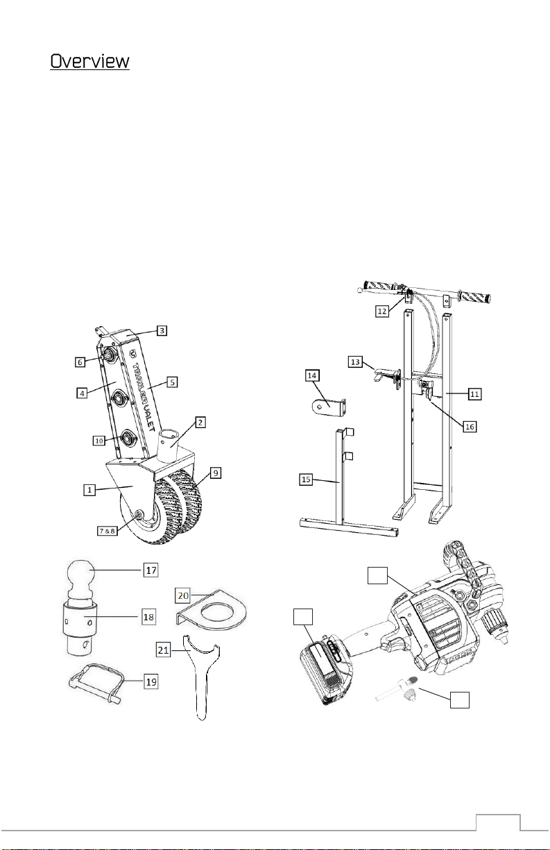
10. Gear Bearing
Accessories
5
16
21. Spanner Wrench
Commercial Drill
24. 60V Lithium-Ion Battery
25. Battery Charger
22
24
23
Upon removing items from packaging, it is very important to thoroughly inspect all parts of the
system before using the device. Any part that is missing or damaged must be immediately replaced.
Contact Trailer Valet Customer Service at 1-844-846-9344 or Support@TrailerValet.com
What’s Included:
1. Wheel Housing
2. Rotating Coupler
3. Brake Cap
4. Side Plates
5. Gear Covers
6. Driveshaft
7. Axle Screw Assembly
8. Wheel Axle
9. Rims and Tires
11. Bracket
12. Handlebar w/ Trigger
13. Drill Lever
14. Drill Mount
15. Kickstand
16. Brake Delay
17. 2” & 2
18. Ball Base
19. Locking Pin
20. Coupling Plate
” Hitch Ball
22. Drill
23. Chuck Key
Page 6

5
Fasteners:
No
Label
Name
Qty 1 A
M8x40 Screw
2
2 A M8 Locking Nut
2
3 B M8x45 Screw
2
4 B M8 Locking Nut
2
5 C M8x50 Screw
2
6 C M8 Locking Nut
2
7 D M8x12 Screw
4
8 E M8x75 Screw
1
9 E M8 Flat Washer
1
10 E M8 Locking Nut
1
11 F 5/8-11x1-3/4 Bolt
1
12 F Flat Washer
1
13 F Spacer
1
14 U-Joint
1
A 1
B 3
A 2
B 4
C 5
C 6
D 7
E 8
E 9
E 10
F 11
F 12
F 13
14
facing away from the screw head.
*Instillation requires an M6 Allen/Hex wrench.
*Install locking nuts with the tapered end
Page 7

6
Step 1: Attach the Handle Bar
Insert the Handlebar w/ Trigger (#12) into the extended bars at the top of the Frame Bracket (#11).
Secure with contents of Fastener Bag A. Tighten the Trigger to handlebar in your desired position.
Step 2: Attach the Drill Lever
Using the contents of Fastener Bag B, Mount the Drill Lever (#13) onto the two uppermost thread
slots on the side of the Frame Bracket (#11). When viewing from the back of the frame (shown
below), the lever will point toward the front.
Page 8

7
Step 3: Attach the Drill Mount
Using the contents of Fastener Bag C, connect the Drill Mount (#14) to the Frame Bracket (#11)
making sure that the protruding side is facing toward the front of the Frame Bracket. The Drill
mount will use the center two thread slots, placing it below the Drill Lever (#13).
Step 4: Attach the Frame to the Trailer Valet Unit
Using the contents of Fastener Bag D, mount the Frame Bracket (#11) to the top of the Trailer Valet
Unit’s Wheel Housing (#1).
Page 9

8
Step 5: Attach Kickstand
Using the contents of Fastener Bag E, connect the Kickstand (#15) to the Frame Bracket (#11). The
screw will fit into the single lowest thread slot on the bracket, below the Drill Mount (#14).
Do not over tighten the kickstand screw. Be sure that Kickstand can rest flush against the Frame.
Page 10

9
Step 6: Connect the Brake
The brake cap (#3) will be fitted to the brake mechanism (#16) on the bracket.
Lift the Brake Cap extensions upward to bring the hooks over the brake delay.
Place the hooks over the screw and release.
Page 11

10
Step 7: Install the Drill
Insert and tighten the U-Joint (Fastener No. 14) into your 60V Drill (#22). Then, connect the U-Joint
to the Driveshaft (#6) on the Trailer Valet Unit.
Using the contents of Fastener Bag F, slot the included bolt through the Drill Mount (#14.) Fit the
included spacer over the bolt before screwing into the threading located on the side of the drill
handle.
If necessary, tighten the drill chuck further with the included Chuck Key (#23). Attach the 60V Drill
Battery (#24) to the drill.
Page 12

11
Step 8: Tension Adjustment
Barrel Adjuster:
Turn clock-wise to decrease tension on the cable.
Locking Nut:
adjuster back into place.
Rear adjuster
Front adjuster
If needed, calibration of both the Drill trigger and Brake Delay are done on the Trigger Handle.
Adjust the rear Barrel Adjuster (shown below) to change the Drill Trigger tension.
Adjust the front Barrel Adjuster (show below) to change the Brake Delay tension.
The Drill Lever cable needs to be tensioned if the lever does not exact enough force onto the Drill
Trigger to adequately drive the unit.
The Brake Delay cable needs to be tensioned if, when releasing the trigger to stop the unit, the
brake makes a sudden grinding noise. This noise is an indication that the brake is engaging before
the gears have stopped moving.
Turn counter clock-wise to increase tension on the Cable.
Turn clock-wise to lock the barrel
Page 13

12
SETUP
Remove all the items from the box. If the
Coupling Plate is not already installed with
the Ball Base, detach the ball from the
Locking Nut, slip the Coupling Plate under
the ball, and reinsert into the Locking Nut.
Secure tightly.
ADJUSTING THE TRAILER HEIGHT
Raise the trailer tongue to where the
coupler is about 17 inches off the ground
(the same height of the ball when the
Trailer Valet is upright).
ATTACHING THE BALL TO COUPLER
1) Slide the Trailer Valet directly under the
coupler.
2) Slip the ball into the coupler and lock the
ball with the coupler latch.
NOTE: Similar to attaching the trailer to
your hitch, you may need to adjust the
position of the ball for it to lock tightly to
the coupler.
3) Raise the trailer slightly so that the
device hangs from the coupler and the
wheels on the Trailer Valet are above
ground. This will enable you to tighten the
Locking Nut.
4) Using the Spanner Wrench, turn the
Locking Nut counter clockwise until the nut
is secured flat against the coupler.
WARNING! Failure to tighten the Locking
Nut against the coupler may cause the ball
to slip out of the coupler.
NOTE: To ensure that the Locking Nut is
securely fastened to the coupler, rock the
device in all directions and continue
tightening until there is no movement by
the device and the Locking Nut remains flat
against the coupler.
ALTERNATIVE METHOD FOR INSTALLING
THE BALL ATTACHMENT:
NOTE: This method is recommended for
heavier trailers and users who have
difficulty securing the ball tightly into the
coupler.
1) Before installing the Ball Attachment into
the Rotating Coupler of the XL, put the ball
into the trailer coupler and lock the ball
with the coupler latch.
2) Using the Spanner Wrench, turn the
Locking Nut counter clockwise until the nut
is secured flat against the coupler.
3) Lower the trailer with the Ball
Attachment into the Trailer Valet XL and
secure using the Rotating Pin.
Page 14

13
Knowing the proper operating techniques for your Trailer Valet can help keep you and
others around you safe. This manual shows basic fundamentals for effective operations.
Apply your knowledge of your Trailer to adjust your techniques to each unique situation.
Step 6: Before Use
1) Be sure your battery pack is charged before use. Follow your drill/driver
manufacturer's recommendation.
2) Check that the drill chuck is tightly secured to the U-Joint. If not, tighten with included
Chuck Key.
3) If your trailer has built-in brakes, they must be disengaged prior to operation of the
Trailer Valet. Consult your trailer manufacturer’s manual/instructions on temporary
brake release. If this is not available to you, please contact Trailer Valet Customer
Support through phone or email for assistance.
WARNING! Always ensure the operator and bystanders are aware of load stability.
4) Lower the trailer gradually until the existing jack is above the ground and the trailer is
completely supported by the Trailer Valet.
NOTE: Keeping the trailer jack close to the ground prevents serious damages from
occurring due to unexpected failures.
Step 7: Operation
Hold the unit firmly when engaging. Pull the trigger on the Handlebar to engage the unit.
The drill will have high initial torque if the drill is engaged too quickly. Begin to move the
trailer as slowly as you are capable and carefully increase the power up to an
appropriate speed.
NOTE: It is important that you steer the device only when you are moving the trailer.
Attempting to turn at a dead stop will place excessive stress on a single tire.
NOTE: When attempting to make sharp turns from a stationary position, move the unit
back and forth slightly while turning until the unit is in the desired position. Then,
proceed to make the turn.
WARNING: DO NOT use the Trailer Valet on slopes and inclines exceeding a strict
maximum of 10 degrees on a paved/concrete surface. This rating is subject to factors
including, but not limited to, alternate surfaces, weight distribution, change in weight
capacity, and use on multi-axle trailers. DO NOT pull up or push down an incline. The
unit must always be on the lower end of any incline. If you have any questions
concerning the use of your Trailer Valet on a slope or incline, please contact us at
(844) 846-9344 or email us at: support@trailervalet.com
Page 15

14
SuperTech S Corp warrants for one year from the purchase date that the product will be in working
condition and will be free from manufacturing defects, provided that installation and use of the
product is in accordance with product instructions. This warranty is only made to the original
consumer purchaser and is non-transferable.
This warranty does not cover:
Limitation of Liability:
EXCEPT AS PROVIDED IN THIS WARRANTY AND TO THE MAXIMUM EXTENT PERMITTED BY LAW,
SUPERTECH IS NOT RESPONSIBLE FOR ANY DIRECT, INCIDENTAL, CONSEQUENTIAL DAMAGES, OR
INJURIES RESULTING FROM ANY BREACH OF WARRANTY OR CONDITION; INCLUDING, BUT NOT
LIMITED TO, LOSS OF USE, LOSS OF REVENUE, LOSS OF ACTUAL OR ANTICIPATED PROFITS, LOSS OF
BUSINESS, LOSS OF OPPORTUNITY, LOSS OF GOOD WILL, LOSS OF REPUTATION, OR ANY DIRECT,
INDIRECT, OR CONSEQUENTIAL LOSS OR DAMAGE WHATSOEVER CAUSED, INCLUDING THE
REPLACEMENT OF EQUIPMENT AND PROPERTY.
Customer Responsibilities:
Customers may be required to provide proof of purchase date, respond to questions designed to
assist with diagnosing potential issues, and follow Trailer Valet’s directions to make a claim on your
warranty.
To make a warranty claim:
Contact us either through:
1. phone: (844) 846-9344
2. email: support@trailervalet.com
3. office: 17970 Ajax Cir, City of Industry CA 91748
TRAILER VALET SHALL HAVE THE EXCLUSIVE RIGHT TO DETERMINE IF A UNIT IS COVERED UNDER
ITS LIMITED MANUFACTURER’S WARRANTY.
Severability:
The invalidity, illegality, or unenforceability of any provision of this warranty shall not render the
other provisions invalid, illegal, or unenforceable.
Governing Law and Jurisdiction
This warranty shall be governed by the laws of the State of California. The courts of California shall
have the exclusive right to adjudicate any disputes arising under or in connection to this warranty.
ALL OTHER WARRANTIES IMPLIED OR EXPRESSED ARE HEREBY DISCLAIMED.
1. Normal wear and tear or normal aging of the product;
2. Consumable parts designed to diminish over time, unless failure occurred due to a
manufacturing defect;
3. Cosmetic damage, including but not limited to scratches and dents;
4. Damage through accident, abuse, neglect, misuse, natural events, or other external
causes;
5. Damage through misapplication, overloading, or improper installation;
6. Damage due to improper maintenance and repair; and/or
7. Product alterations.
Page 16

Copyright 2018 by Supertech S. Corporation. All right reserved. No portion of this
manual or any artwork contained herein may be reproduced in any shape or form
without the express written consent of Supertech S. Corporation.
For further information or if you have any questions, please contact:
SUPERTECH S. CORP.
17970 Ajax Cir
City of Industry CA 91748
Customer Service: (844) 846-9344
Email: support@trailervalet.com
Or visit: www.trailervalet.com
 Loading...