

Traid TRIUMPH SS SERIES, Triumph 300, Triumph 500, Triumph 750, Triumph 1000 Operating And Maintenance Manual
...
TRIUMPH SS SERIES
High Efficiency Condensing Boiler
300MBH – 2000MBH
OPERATING AND MAINTENANCE MANUAL
1/26/2014
TRIAD Boiler Systems, Inc.
West Chicago, IL 6018
888-526-5245

Contents
FORWARD ...................................................................................................................................................... 6
Documents Unique to your boiler ............................................................................................................. 7
Supplimentary Manuals ............................................................................................................................. 7
Definitions, Standards, & Sources ............................................................................................................. 8
Introduction to safety ................................................................................................................................ 8
What to do if you smell gas ....................................................................................................................... 9
Approvals & Recordkeeping .................................................................................................................... 10
Applicable Regulations in the U.S. market .............................................................................................. 10
Warnings ...................................................................................................................................................... 11
1 Labeling, Signage, Handling Options ........................................................................................................ 12
2.0 Boiler Component Identification ........................................................................................................... 17
2.1 Boiler Specifications and Dimensions .................................................................................................... 18
2.1.1 Cutaway of Combustion Chamber and Heat Exchanger………………………………………………………………….23
2.2 Typical basic water level and temperature controls ............................................................................. 24
2.3 Burner Mount ........................................................................................................................................ 25
2.4 Gas Train…………………………………………………………………………………………………………………………………………..26
2.5 Example fuel train schematics ............................................................................................................... 26
2.6 Example wiring diagrams ....................................................................................................................... 27
3.0 Specifications ......................................................................................................................................... 28
4.0 Boiler Installation ................................................................................................................................... 29
4.1 Receiving the boiler ............................................................................................................................... 29
4.2 Unloading the boiler-burner unit .......................................................................................................... 30
4.3 Boiler unloading instructions ................................................................................................................. 30
4.4 The boiler room ..................................................................................................................................... 31
Fresh & Ventilation air ............................................................................................................................. 31
Lighting .................................................................................................................................................... 31
4.5 Installing the Boiler ................................................................................................................................ 31
Flue .......................................................................................................................................................... 32
Condensate Drain .................................................................................................................................... 32
Water Connections .................................................................................................................................. 32
Inverting Door Aperture (Model 300 & 500) ........................................................................................... 30
Inverting Door Aperture (Models 750 - 2000) ......................................................................................... 33
Pressurized Boiler Connection ................................................................................................................. 33
Furnace Drawer ...................................................................................................................................... 34
2 TRIAD Boiler Systems, Inc.
West Chicago, IL
www.triadboiler.com

4.6 Extended storage procedure for boilers not yet installed. ................................................................... 35
4.7 Installation of Loose shipped items ....................................................................................................... 35
4.8 Electrical Installation ............................................................................................................................. 36
Power for Electrically Operated Controls. ............................................................................................... 36
Remote Emergency shutdown switches ................................................................................................. 37
4.9 Miscellanious installation guidelines ..................................................................................................... 37
Software & Safety .................................................................................................................................... 37
Flame Safeguard ...................................................................................................................................... 37
Venting of Gas Controls ........................................................................................................................... 37
4.10 Boiler stack connection ....................................................................................................................... 37
4.11 Vent material selection ....................................................................................................................... 38
5 Plumbing your boiler ................................................................................................................................ 39
5.1 Fuel supply & connections ..................................................................................................................... 39
5.2 Boiler connections, general ................................................................................................................... 39
5.3 Water connections ................................................................................................................................ 39
5.4 Hot water boilers supply & return connections .................................................................................... 40
5.5 Drains ..................................................................................................................................................... 40
5.6 Drain connections .................................................................................................................................. 40
5.7 Safety relief valves (SRV) ....................................................................................................................... 41
5.8 SRV discharge piping ............................................................................................................................. 41
6 Boiler start-up ........................................................................................................................................... 42
6.1 Operating data ....................................................................................................................................... 42
6.2 Start-up guidelines................................................................................................................................. 42
6.3 Tools & gauges ....................................................................................................................................... 43
6.4 Fuel guidelines ....................................................................................................................................... 43
6.5 Cleaning and filling a new boiler ........................................................................................................... 43
6.6 Firing a new boiler ................................................................................................................................. 44
6.7 Boil-out procedure ................................................................................................................................ 44
6.8 Start-up of hot water boilers ................................................................................................................. 46
6.9 Good Practice recommendations for hot water boilers ........................................................................ 47
6.10 Guide lines for hot water boiler heating system. ................................................................................ 47
Condition: Boiler Warm – System Warm ................................................................................................ 47
Shut down of hot water boiler heating system ....................................................................................... 47
7 Operation .................................................................................................................................................. 48
7.1 Safety relief valves ................................................................................................................................. 48
3 TRIAD Boiler Systems, Inc.
West Chicago, IL
www.triadboiler.com

7.1.2 Safety relief valve tests ....................................................................................................................... 48
Try Lever Test .......................................................................................................................................... 48
Safety Relief Valve Test: .......................................................................................................................... 49
7.2 Gauges ................................................................................................................................................... 50
7.2.1 Pressure gauges: ................................................................................................................................. 50
7.2.3 Pressure gauge range: ........................................................................................................................ 50
7.2.4 Pressure gauge accuracy: ................................................................................................................... 50
7.2.5 Pressure gauge calibration ................................................................................................................. 50
7.2.6 Temperature gauges........................................................................................................................... 50
7.2.7 Pressure or altitude gauges ................................................................................................................ 51
7.2.8 Stack thermometers ........................................................................................................................... 51
7.3 Temperature controls ............................................................................................................................ 51
7.3.1 High limit: ........................................................................................................................................... 51
7.3.2 Operator: ............................................................................................................................................ 51
7.3.3 Firing rate control: .............................................................................................................................. 51
7.4 Maintenance on temperature limiting controls .................................................................................... 51
7.5 Example of control set point adjustment procedure ............................................................................ 52
7.7 Water level controls .............................................................................................................................. 52
7.7.1 Electric probe type low-water fuel cutoffs ......................................................................................... 52
7.7.2 Low-water fuel cutoff and water feeder maintenance. ..................................................................... 52
7.7.3 Pushbutton Shunt ............................................................................................................................... 53
7.7.4 LWCO .................................................................................................................................................. 53
7.7.5 Water level manual reset ................................................................................................................... 53
7.8 Water level operations .......................................................................................................................... 53
7.8.1 Maintaining Proper Water Level ........................................................................................................ 53
7.9 Water Treatment ................................................................................................................................... 54
7.9.1 Heating boilers .................................................................................................................................... 55
7.9.2 Water treatment guidelines ............................................................................................................... 55
Get professional help .............................................................................................................................. 55
Oil & water don't mix .............................................................................................................................. 56
Heating boilers should not breathe ......................................................................................................... 56
7.10 Access openings and burner mount .................................................................................................... 56
7.10.1 Burner mount ................................................................................................................................... 56
7.10.2 Refractory ......................................................................................................................................... 56
8 Maintenance ............................................................................................................................................. 56
8.1 Spare Parts. ............................................................................................................................................ 57
4 TRIAD Boiler Systems, Inc.
West Chicago, IL
www.triadboiler.com

8.2 Maintenance schedule .......................................................................................................................... 57
8.2.1 Daily procedure, also reference the burner manual’s procedures. ................................................... 57
8.2.2 Weekly procedure, also reference the burner manual’s procedures. ............................................... 58
8.2.3 Monthly procedure, also reference the burner manual’s procedures. ............................................. 58
8.2.4 Semi-Annual procedure, also reference the burner manual’s procedures. ....................................... 59
8.2.5 Annual procedure, also reference the burner manual’s procedures. ................................................ 59
8.3 Detailed Empty inspection..................................................................................................................... 60
Safety Checklist for Inspection ................................................................................................................ 61
Water Side Checklist ................................................................................................................................ 61
Fire Side Checklist .................................................................................................................................... 61
Look for corrosion of pressure parts: ...................................................................................................... 61
Look for erosion: ...................................................................................................................................... 62
External Checklist: ................................................................................................................................... 62
8.4 Limit control tests .................................................................................................................................. 62
8.4.1 High & Low gas pressure switch limit test & adjustment ................................................................... 62
For setting and testing the gas pressure switches: ................................................................................. 63
8.4.2 Electrical Limit Controls. ..................................................................................................................... 63
9 TROUBLESHOOTING ................................................................................................................................. 63
To stop burner ......................................................................................................................................... 64
Burner adjustments ................................................................................................................................. 64
Switch problems ...................................................................................................................................... 64
Leaking ..................................................................................................................................................... 64
Fan rotation ............................................................................................................................................. 64
10 Out of service operations ....................................................................................................................... 65
10.1 Shutdown............................................................................................................................................. 65
10.2 Boiler taken out of service ................................................................................................................... 65
10.3 Boiler laid up dry .................................................................................................................................. 65
10.4 Boiler laid up wet procedure ............................................................................................................... 66
10.5 Re-commissioning ............................................................................................................................... 66
5 TRIAD Boiler Systems, Inc.
West Chicago, IL
www.triadboiler.com

FORWARD
TRIAD Boiler Systems has a manufacturing history of over 80 years. TRIAD patented the original isolated,
modular boiler system concept. Each boiler / burner package has been specifically matched to provide
optimal performance. The boilers, however, are only a part of the complete operating system. They can only
meet their ratings if the system is properly designed and if the boilers receive proper care.
Two major things must be focused on to achieve successful implementation: Proper System Design and
Proactive Preventive Maintenance. While the TRIAD Boiler website www.triadboiler.com may address some
issues, a design engineer should be involved. This Operations and Maintenance Manual addresses many
issues regarding usage.
It is important that the system design matches the performance of the boiler. A compatible design that
addresses combustion air, correct system sizing, fuel and water supply, and breeching is crucial, and should
be the responsibility of the system design engineer who must also ensure local code compliance. The boilers
will meet their full potential when part of an appropriate system design.
Efficient burner operation is highly dependent on proper adjustment, adequate combustion air, and correct
breeching. Make sure you carefully read the burner Operating and Maintenance Manual. Incorrectly dealing
with these issues can result in, among other things, a loss of efficiency, higher operating costs, sooting,
frequent cleaning, and high carbon monoxide (CO) output.
The successful, long-term operation of the boiler is dependent on the quality of its water. Failure to provide
suitable water will result in corrosion and the build-up of scale and mud / sludge / sediment causing
inefficient thermal transfer, an associated loss of efficiency, higher operating costs, and eventually lead to
premature boiler failure.
Being cognizant of these issues, and taking proper steps when required, should result in many years of
successful boiler operation.
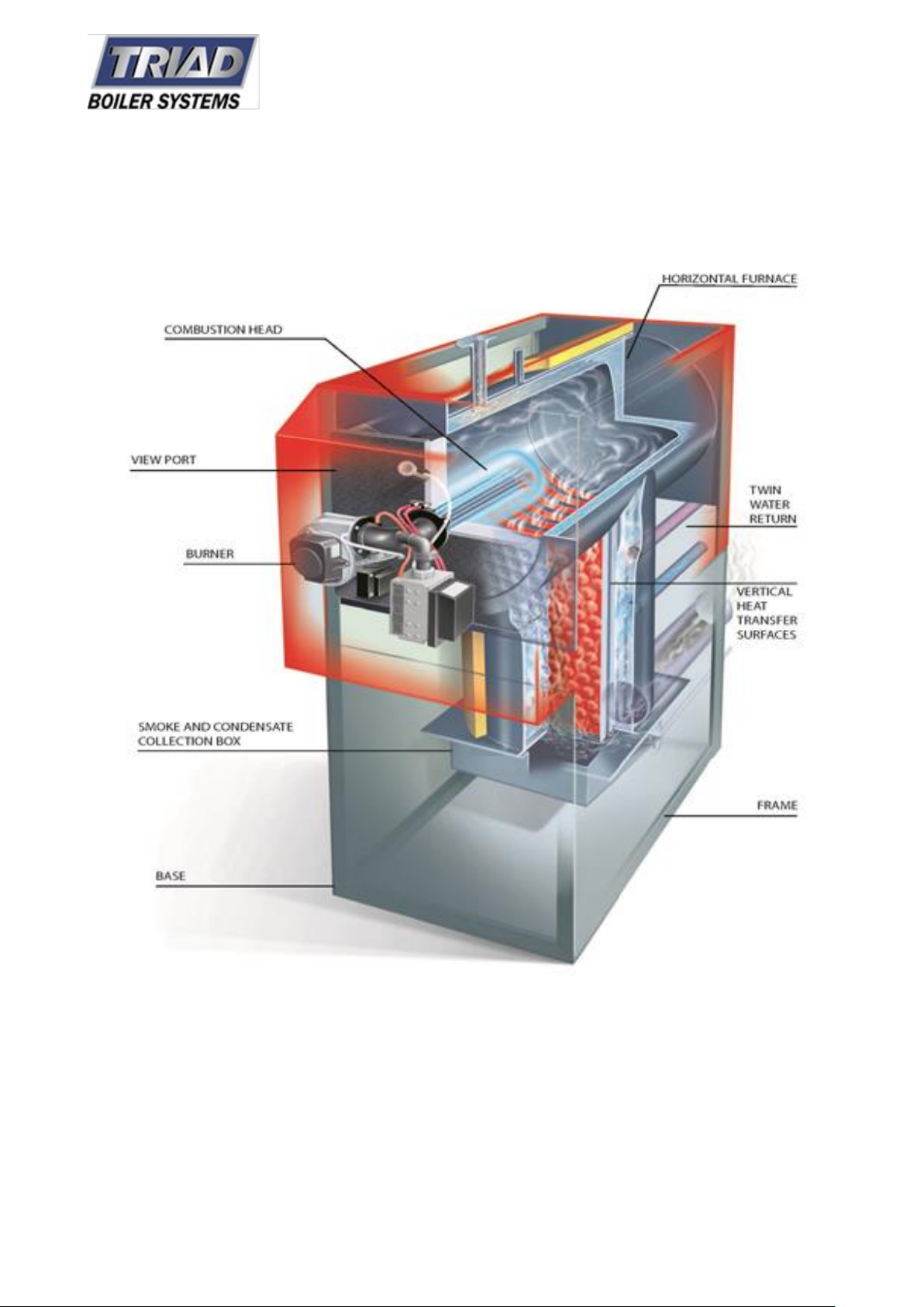
TRIUMPH SS HIGH EFFICIENCY BOILERS
TRIAD is pleased to introduce a new line of High Efficiency boilers, the TRIUMPH SS series. This product line
is designed with a large horizontal combustion chamber matched with a specially engineered vertical
condensing section in stainless steel AISI 316 Ti. These elements are immersed in water contained in a
horizontal boiler drum with a vertical column to which the system inlet and outlet connections are fitted. All
the burners, controls, and pumps are all first quality name-brand OEM components.
These boilers reach very high efficiency levels as the flue gases not only are released at a temperature little
higher than that of the system return water, but also a large part of the water vapor contained in the flue
gases is condensed, recovering the latent heat of condensation.
Because the flame path is designed to go through the combustion chamber without inversion, the formation
of Nitrogen Oxides (NOx) is limited as much as possible. This is because NOx typically forms when the flame
remains at high temperature in the combustion chamber for long periods.
6 TRIAD Boiler Systems, Inc.
West Chicago, IL
www.triadboiler.com

The TRIUMPH SS series boilers place no limit on the return water temperature, and reach the highest
performance when the return temperature is lower than 135°F. At higher temperatures (as with any
condensing boiler) there is no water vapor in the flue gas, so it is not possible to recover any latent heat. The
efficiency of Triumph SS boilers is rather high even with traditional-temperature heating systems.
READ AND SAVE THESE INSTRUCTIONS FOR REFERENCE. These manual and associated documents are to
be kept with the boiler and in legible condition for the life of the boiler.
This manual will refer to the burner manual (Powerflame or Weishaupt) when appropriate. A double asterisk
(**) is used to indicate that your boiler manual should also be checked for information on the topic being
covered unless otherwise noted. In addition to the boiler and burner working together, there are controls,
switches, valves, and other components on your boiler assembled specific to each end user. A list of exact
components, and information about them, are appended to this manual. All of these documents and devices
work together to safely operate your boiler.
Documents Unique to your boiler
Triad documents are created unique to each boiler and are appended to this manual
Document # of pages Page #/Location
Specification sheets 4 Appendix 1
Ratings and dimension drawing, 1 Appendix 2
Recommended spare parts, 1 to 3 Appendix 3
List of component manuals 1 to 4 Appendix 4
ASME data reports 1 to 12 pages Appendix 6
MSDS Information (If supplied) 0 to 9 Appendix 7
Wiring drawing(s) can be large format Last
Supplimentary Manuals:
This manual is intended to be used in conjunction with other documents.
Burner manual, and manuals that comes with the burner. Appendix 10
Manuals for other components supplied with the boiler. Appendix 11
NOTE: Warranty validation/Start-up report information sheet must be filled out and return to TRIAD within
three weeks of when the burner is first turned on and within two months of shipment of boiler to maintain
your warranty. Also note that boil-out procedures, a slow initial warm up, and proper water treatment are
required to maintain your warranty.
7 TRIAD Boiler Systems, Inc.
West Chicago, IL
www.triadboiler.com

DEFINITIONS AND TERMINOLOGY
ASME: American Society of Mechanical Engineers
ASME CSD-1: Controls and Safety Devices for Automatically Fired Boilers
BPVC: ASME boiler and pressure vessel code.
Section IV: Portion of BPVC that applies to water boilers not exceeding 160 PSIG or 250°F and Steam boilers
not exceeding 15 PSIG
Heating boiler: hot water boiler
Water boiler: Boiler that supplies hot water
LWCO: Low-water cutoff, or Low-water fuel cutoffs
Aux LWCO: Auxiliary Low water cutoff
LWCO mark: Vertical position on boiler where the primary LWCO operates
ANSI: American National Standards Institute
150# class: ANSI standard of flanged piping connections,
NPS: Nominal pipe size
NPT: National pipe thread (tapered)
MAWP: Maximum allowable working pressure
Set point: A specific value of pressure or temperature used in a control where it will switch on or off.
Aquastat: Water temperature control device
BHP: Boiler horse power is equivalent to 33,475 Btu/Hr.
PSI: Pounds per square inch
PSIG: PSI gage reading.
In. WC: Inches of water column. Units of pressure where one (1) PSI = 28 In. WC (28” WC)
UL: Underwriters Laboratories Inc.
UL Mark: Signage on the boiler designating UL approval
UL 795: Commercial-Industrial Gas Heating Equipment
UL 353: Limit Controls
cUL: Verification to Canadian Requirements by Underwriters Laboratories Inc.
CSA: Canadian Standards Association
CSA 22.1: Canadian Electrical Code Part 1
CSA B149: Natural Gas & Propane Code
NFPA: National Fire Protection Agency
NFPA 54: National Fuel Gas Code
NFPA 70: National Electric Code, AKA: NEC
IFGC: International Fuel Gas Code
R&D drawing: Ratings and Dimensions drawings. AKA: General Arrangement.
Introduction to safety
WARNING! The improper installation, adjustment, service, maintenance, or operation of this
equipment can result in fire, explosion, series injury, or death.
Refer to this Triumph manual and the PowerFlame burner manual. For assistance or additional
information consult a qualified installer, service agency, or fuel supplier as appropriate.
8 TRIAD Boiler Systems, Inc.
West Chicago, IL
www.triadboiler.com

DO NOT STORE OR USE GASOLINE OR ANY OTHER FLAMMABLE LIQUIDS IN THE VICINITY OF THIS OR ANY
OTHER APPLIANCE. DO NOT USE GASOLINE, CRANKCASE DRAININGS, OR ANY OIL CONTAINING GASOLINE.
NEVER BURN GARBAGE OR PAPER IN THE UNIT, AND NEVER LEAVE COMBUSTABLE MATERIAL AROUND IT.
All Personnel involved with the startup, maintenance, or adjustment of this boiler must read and understand
the entire contents of this manual prior to any startup or adjustment being made to the boiler and related
components. Installation and service must be performed by a qualified installer or certified service
technician.
Safe and reliable operation is dependent to a large extent upon the skill and attentiveness of the operator
and the maintenance personnel. Operating skill implies the following:
Knowledge of fundamentals
Familiarity with equipment
Suitable background of training and experience
Full and effective use should be made of manufacturer's instruction books on operation and maintenance.
Of special importance are written procedures prepared expressly for each installation by the manufacturers'
service engineers and qualified personnel from the operating organization before and during the
commissioning period. These procedures are based on actual experience and often include invaluable
information on what the equipment is expected to do. Limitations critical to safe and reliable operations are
also given. Control systems vary in complexity from computer control to manual operation.
Regardless of the type of system used, the operators should be thoroughly trained so that they can maintain
safe and continuous operation during changeover from automatic to manual control as well as to continue
operation by manual control if the automatic systems are out of service. The operator should have
instrumentation at the point of manual operation to permit him to be aware of operating conditions at all
times. Regularly scheduled auto-manual changeover, manual operation, and emergency drills to prevent loss
of these skills are recommended.
What to do if you smell gas:
Do not try to light any appliance
Do not tough any electrical switch
Do not use any phone in your building
Immediately call your gas supplier from a neighbors phone
Follow the gas supplier’s instructions
If you cannot reach your gas supplier, call the fire department.
9 TRIAD Boiler Systems, Inc.
West Chicago, IL
www.triadboiler.com

Approvals & Record keeping
All TRIAD boilers are designed, manufactured, and stamped to the ASME PRESSURE VESSEL CODE. Refer to
the signage information section to determine the approvals that have been applied to your boiler.
THE INSTALLATION OF THIS BOILER SHALL BE IN ACCORDANCE WITH LOCAL CODE AND REGULATIONS OF
AUTHORITIES HAVING JURISDICTION.
BOILERS SHALL BE OPERATED BY QUALIFIED PERSONNEL. BOILERS SHALL BE INSTALLED AND SERVICED BY
QUALIFIED PERSONNEL ONLY OR THE WARRANTY WILL BE INVALIDATED.
Boilers intended for Canadian markets, refer to the following regulations as applicable:
The equipment shall be installed in accordance with the current Installation Code for Gas Burning Appliances
and Equipment, CSA B149, and applicable Provincial Regulations for the class; which should be carefully
followed in all cases. Authorities having jurisdiction should be consulted before installations are made.
Wiring shall be in accordance with the CSA 22.1 Canadian Electrical Code, Part I.
The installation of the unit shall be in accordance with the regulations of the authorities having jurisdiction
APPLICABLE REGULATIONS FOR US MARKET:
NFPA54: National Fuel Gas Code
NFPA70: National Electrical Code
IFGC: International Fuel Gas Code
All drawings, wiring diagrams, schematic arrangements, manufacturers’ descriptive literature, and spare
parts lists, and written operating instruction should be kept permanently in the boiler room or other suitable
location so it will be available to those who operate and maintain the boiler. Where space permits, drawing
and diagrams should be frame or sealed in plastic and hung adjacent to the related equipment. Other
materials should be assembled and enclosed in a suitable binder. When change or additions are made, the
data and drawings should be revised accordingly.
READ AND SAVE THESE INSTRUCTIONS FOR REFERENCE.
Some states and municipalities require licensing or certification of personnel who operate or maintain
heating equipment. Also, some authorities require posting of inspection certificates in the boiler room. The
supervisor in charge of a given installation should make sure such requirements are met.
10 TRIAD Boiler Systems, Inc.
West Chicago, IL
www.triadboiler.com
GENERAL WARNINGS
Each boiler is provided with a data plate that can be found in the envelope with the boiler documents. The
plate lists:
Serial number or identification code;
Rated thermal output;
Furnace thermal output;
Types of fuels that can be used;
Max operating pressure.
A manufacturer's certificate is also provided which certifies the hydrostatic pressure test.
The installation must be performed in compliance with the regulations in force by professionally qualified
personnel. The term “professionally qualified personnel” means persons with specific technical skills in the
sector of heating system components.
INCORRECT INSTALLATION MAY CAUSE DAMAGE TO PERSONS, ANIMALS OR OBJECTS FOR WHICH THE
MANUFACTURER CANNOT BE HELD RESPONSIBLE.
At the first start up, all regulation and control devices positioned on the control panel should be checked for
efficiency. The guarantee shall be valid only upon compliance with the instruction given in this manual.
IMPORTANT: This boiler has been designed to heat hot water to a temperature lower than the boiling point
at atmospheric pressure and must be connected to a heating plant and/or a domestic hot water plant within
the limits of the boiler performance and output.
WARNING!
THE BOILER MUST BE INSTALLED IN A ROOM WHICH COMPLIES WITH THE APPROPRIATE
VENTILATION REQUIREMENTS. READ THE INSTALLATION AND USER INSTRUCTION BEFORE
INSTALLING AND LIGHTING THE BOILER.
11 TRIAD Boiler Systems, Inc.
West Chicago, IL
www.triadboiler.com
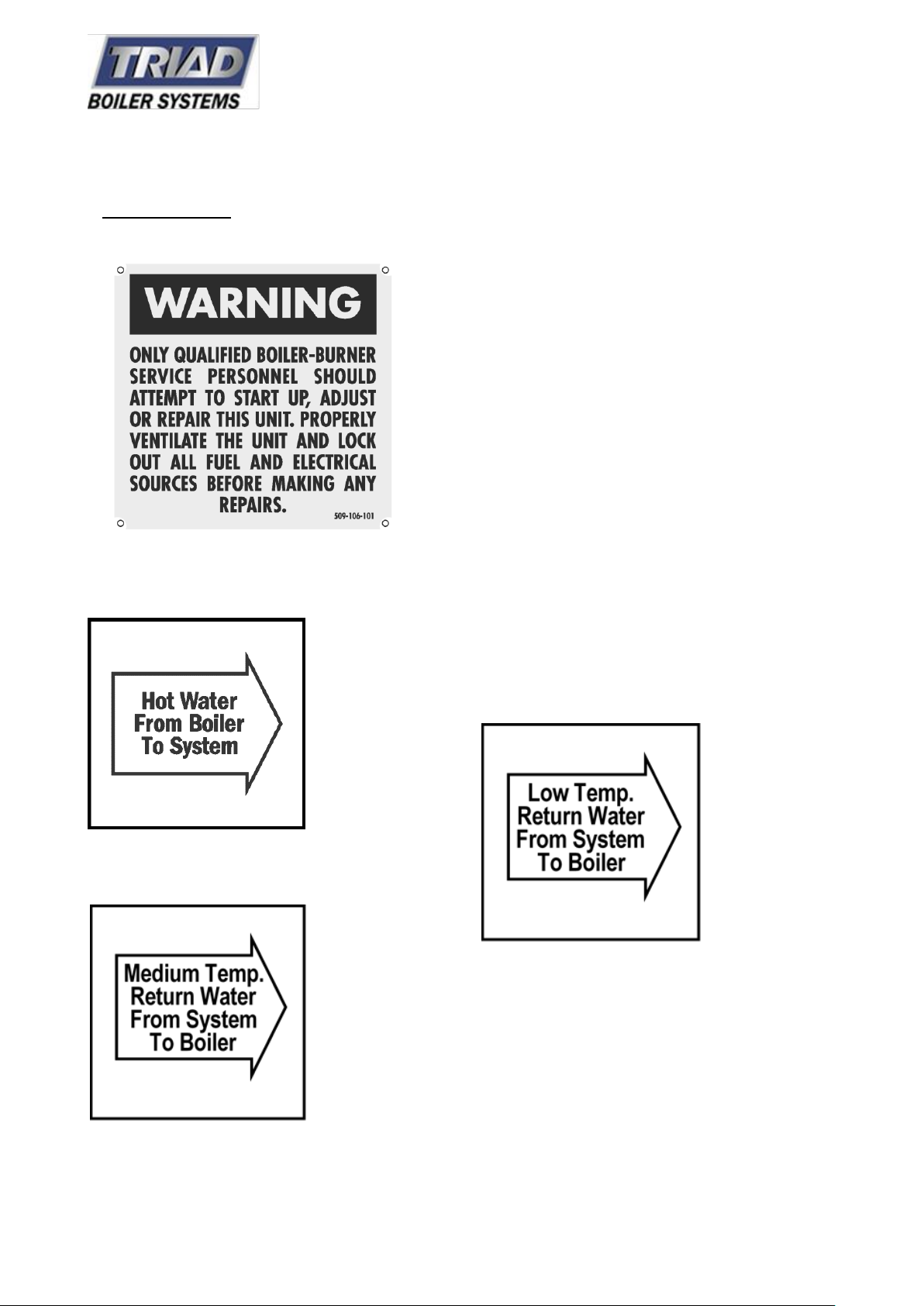
Warning plate:
Every boiler includes
1.0 BOILER LABELING AND SIGNAGE:
this warning mounted on the front doors of the boiler close to eye level.
Supply Water Label:
Medium Temperature Return Water Label:
Low Temperature Return Water Label:
12 TRIAD Boiler Systems, Inc.
West Chicago, IL
www.triadboiler.com
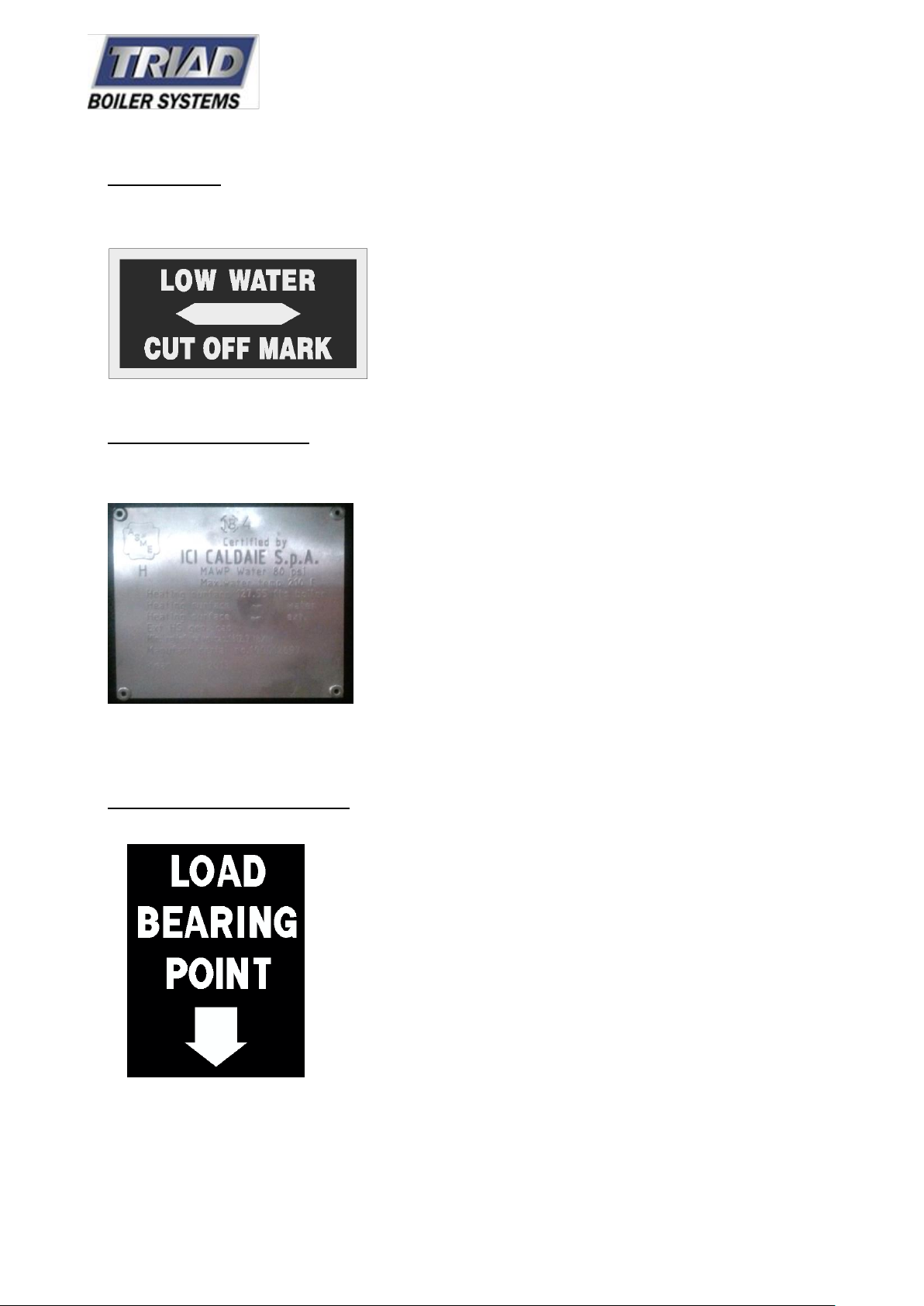
LWCO mark:
Used to determine the correct elevation of the LWCO switch. Line this up with the primary level
mark on the LWCO
ASME Drum stamping:
The ASME “H” Stamp is riveted directly to the boiler frame when ASME approval is given and
is located above the medium temperature return to the left.
Load Bearing Point sticker:
Besides the lifting lugs, this shows the only locations the boiler should be lifted from.
.
13 TRIAD Boiler Systems, Inc.
West Chicago, IL
www.triadboiler.com
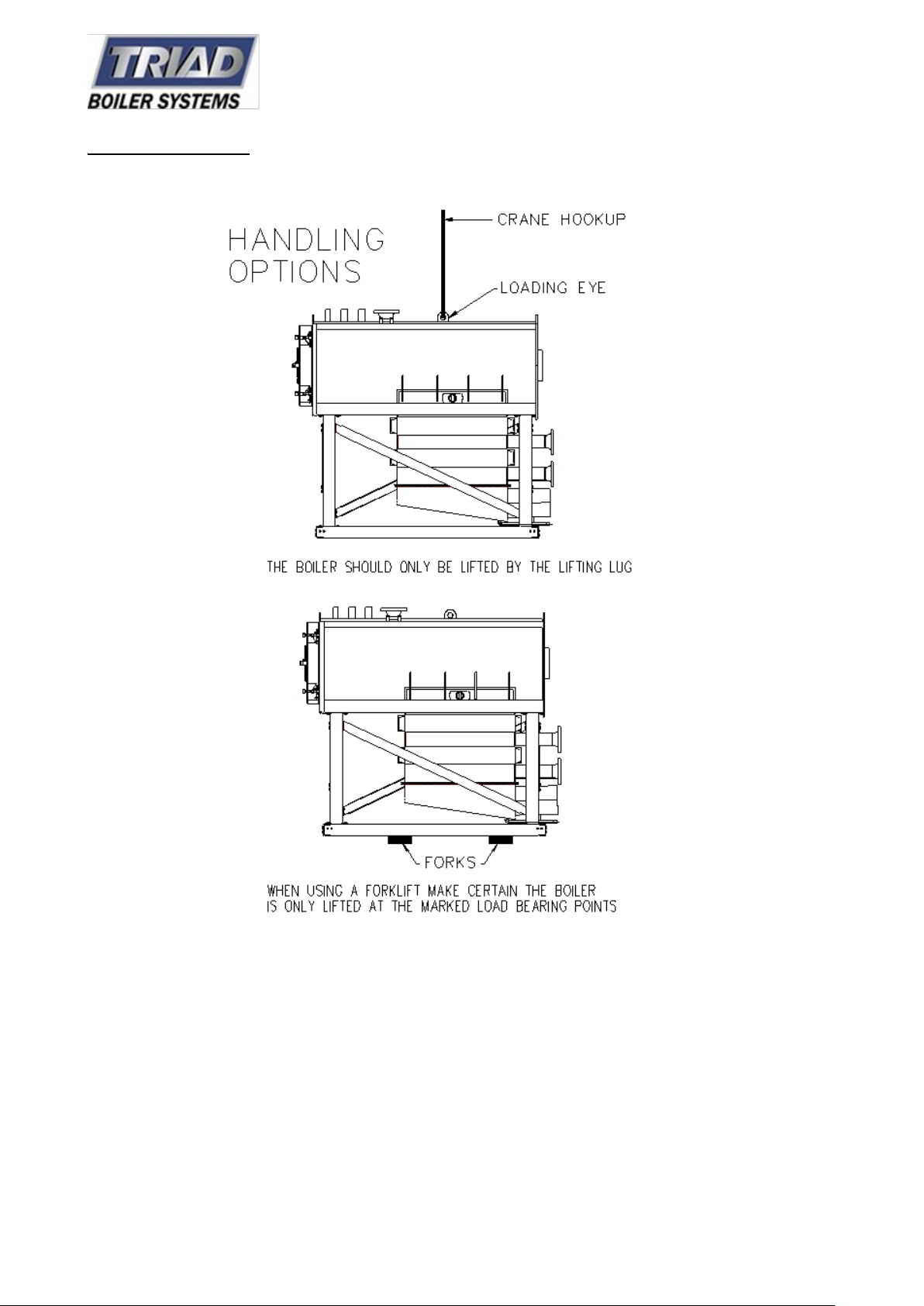
Handling Options:
14 TRIAD Boiler Systems, Inc.
West Chicago, IL
www.triadboiler.com
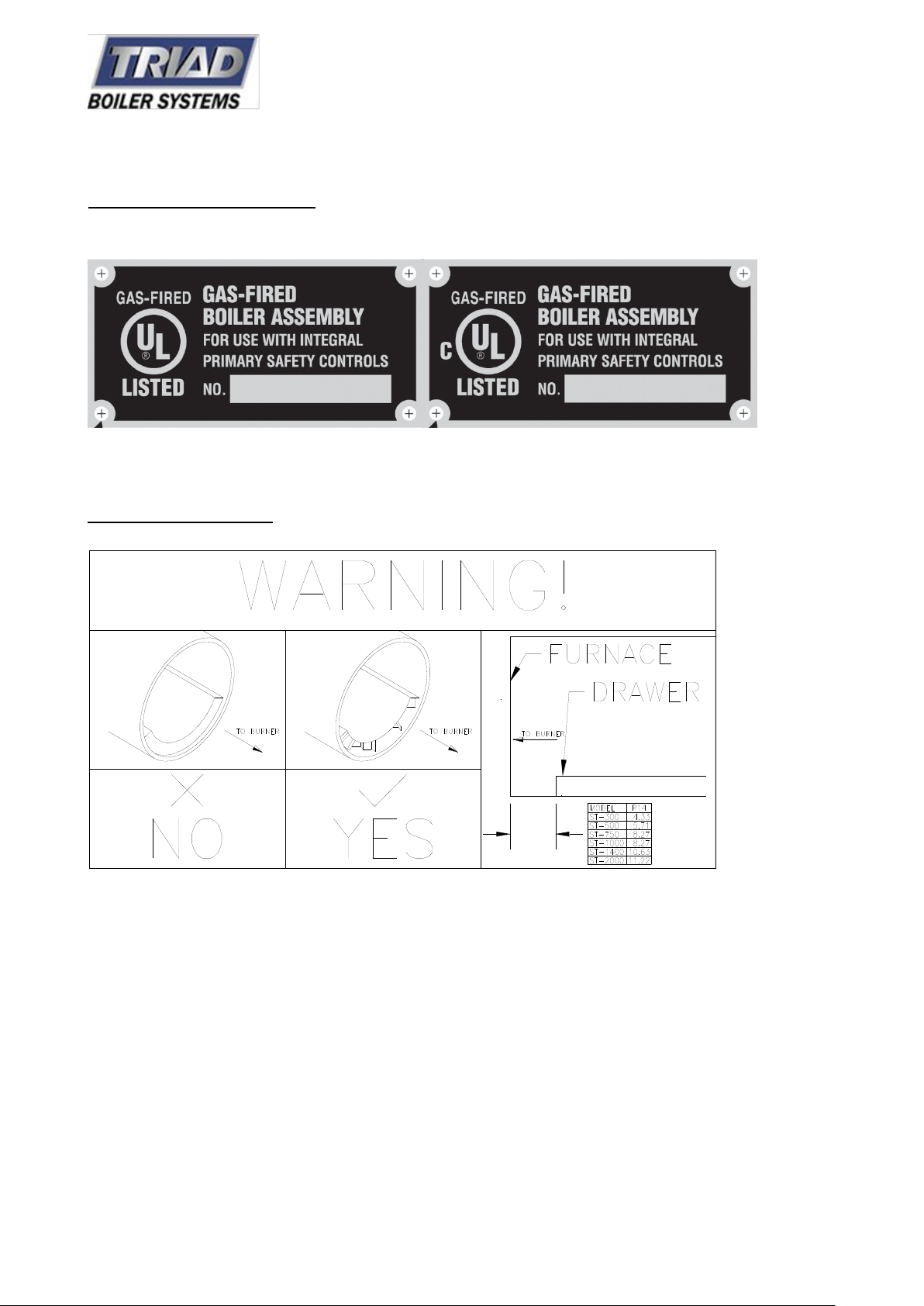
UL and CUL boiler stickers:
Baffle Warning Label
15 TRIAD Boiler Systems, Inc.
West Chicago, IL
www.triadboiler.com
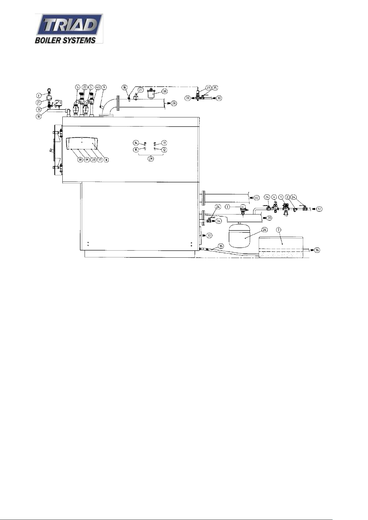
2.0 Boiler Component Identification
16 TRIAD Boiler Systems, Inc.
West Chicago, IL
www.triadboiler.com
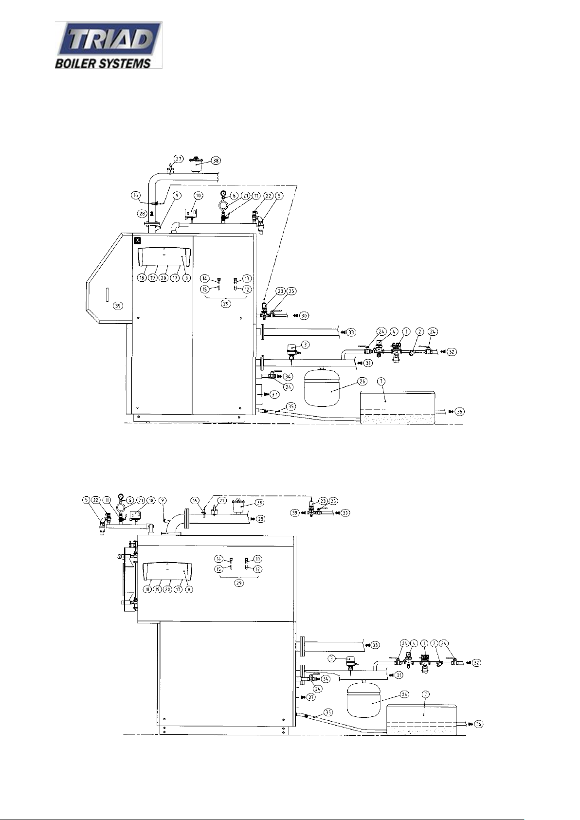
2.1 Boiler Specifications and Dimensions
Model 300 & 500
Model 750 & 1000
17 TRIAD Boiler Systems, Inc.
West Chicago, IL
www.triadboiler.com
Model 1400 & 2000
1 Hydraulic disconnect switch
2 ‘Y’ strainer
3 Water flow switch
4 Filling unit
5 Relief Valve with articulated joint
6 Pressure gauge
7 Acid condensate neutralizer
8 Boiler switchboard
9 Inspection well
10 Safety pressure switch
11 Pressure gauge cock
12 Thermometer probe
13 Safety thermostat probe
14 Regulation thermostat probe n°1
15 Regulation thermostat probe n°2
16 Fuel shut-off valve probe
17 Thermometer
18 Regulation thermostat n°1
19 Regulation thermostat n°2
20 Manual reset safety thermostat
21 Shock absorbing pipe
22 Safety valve n° 1 (the 2 nd has a heating
capacity above 580 kW)
23 Fuel shut-off valve
24 Manual shut-off valve
25 Manual shut-off valve for gas
26 Expansion vessel
27 Level probe glow plug (optional)
28 System flow
29 Probe sleeves inside the boiler
30 Gas inlet
31 Low temperature return
32 Return water inlet from the plant
33 Medium temperature return
34 Boiler exhaust
35 Acid condense outlet
36 Neutralized condense outlet
37 Outlet flue gas
38 Air vent valve
39 Burner
40 Safety valve n° 2 (heating capacity above 580
kW)
18 TRIAD Boiler Systems, Inc.
West Chicago, IL
www.triadboiler.com
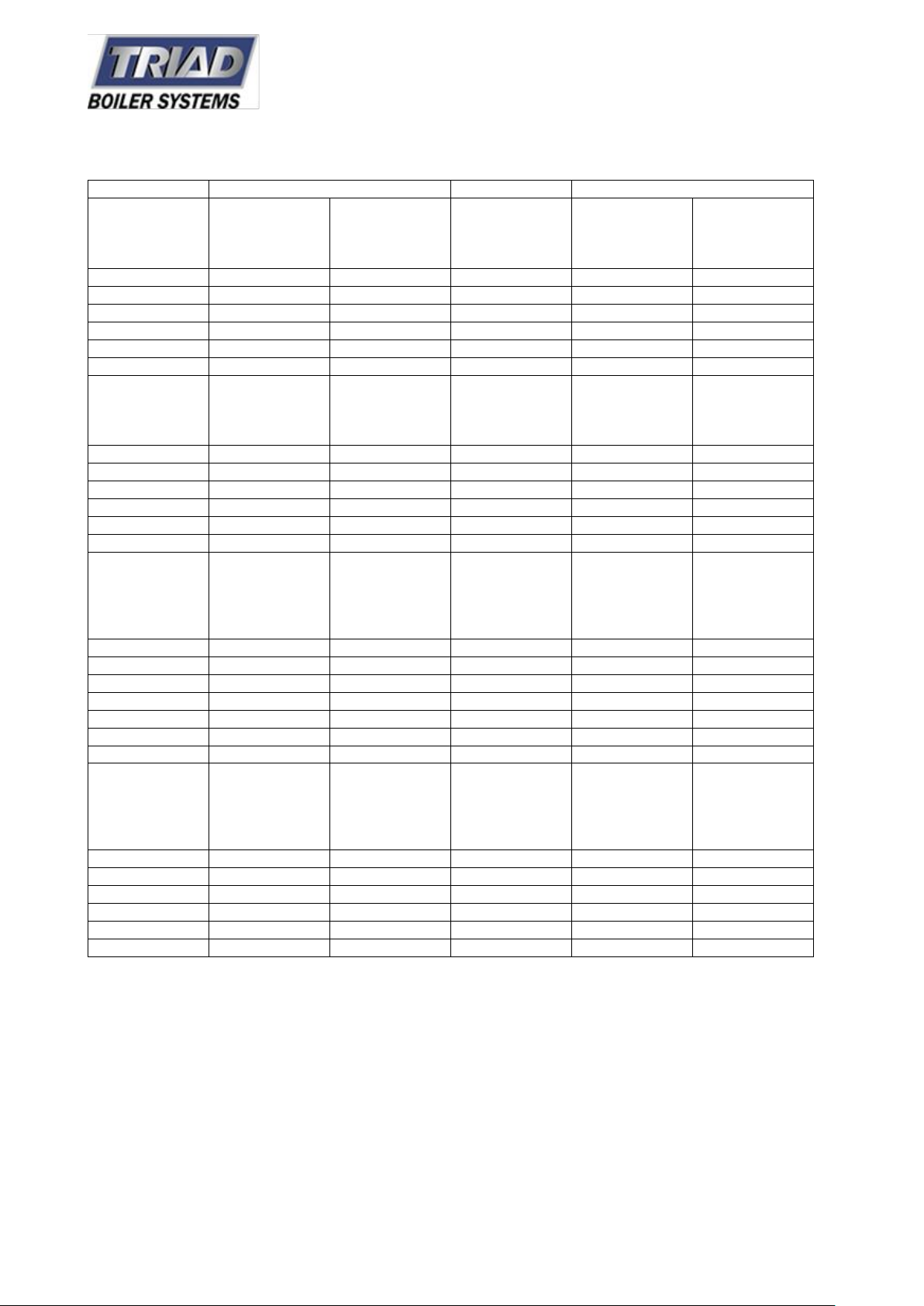
Model
Heat Output
Heat Input
Efficiency
Medium Temp
150F
Btu/hr
Temp
Flow/Return
50/86F
Btu/hr
Btu/hr
Medium Temp
150F
%
Temp
Flow/Return
50/86F
%
Triumph 300
296,857
324,154
300,269
98.3
107.5
Triumph 500
375,336
409,458
382,160
98.3
107.5
Triumph 750
634,659
692,666
644,896
98.3
107.5
Triumph 1000
832,564
907,631
846,212
98.3
107.5
Triumph 1400
1,385,331
1,518,405
1,412,629
98.3
107.5
Triumph 2000
1,743,607
2,043,876
1,774,316
98.3
107.5
Minimum Output
Medium Temp
150F
Btu/hr
TempFlow/Return
50/86F
Btu/hr
Minimum Input
Btu/hr
Efficiency
Medium Temp
150F
%
TempFlow/Return
50/86F
%
Triumph 300
9,8952
109,189
98,952
98.5
109
Triumph 500
126,249
139,898
126,249
98.5
109
Triumph 750
208,141
232,026
211,553
98.5
109
Triumph 1000
276,384
307,093
279,796
98.5
109
Triumph 1400
464,052
515,234
470,876
98.5
109
Triumph 2000
580,065
644,896
590,301
98.5
109
Pressure losses
flue gas side
Heat loss thru
chimney
For condensing
temp flow return
50/86F
Heat loss thru
casing
For condensing
temp flow return
50/86F
Heat loss with
burner off
For condensing
temp flow return
50/86F
Flue gas temp at
output air 20c
For condensing
temp flow return
50/86F
In w.c. % % % F
Triumph 300
0.32
1.5
0.3
0.1
122
Triumph 500
0.40
1.5
0.3
0.1
122
Triumph 750
0.60
1.5
0.3
0.1
122
Triumph 1000
0.80
1.5
0.3
0.1
122
Triumph 1400
0.93
1.5
0.3
0.1
122
Triumph 2000
1.01
1.5
0.3
0.1
122
Condensate
Production
Temp Flow
Return 50/30c
Lb/hr
Pressure Losses
waterside
DT=12k
In w.c.
Design Pressure
psi
Capacity
gal
Weight
lb
Triumph 300
24.5
4.83
72.52
39.6
485
Triumph 500
31.1
7.64
72.52
55.5
617
Triumph 750
52.3
7.64
72.52
81.4
1146
Triumph 1000
68.7
9.65
72.52
75.3
1301
Triumph 1400
114.5
6.44
72.52
103.6
2271
Triumph 2000
143.9
10.46
72.52
147.9
2712
19 TRIAD Boiler Systems, Inc.
West Chicago, IL
www.triadboiler.com
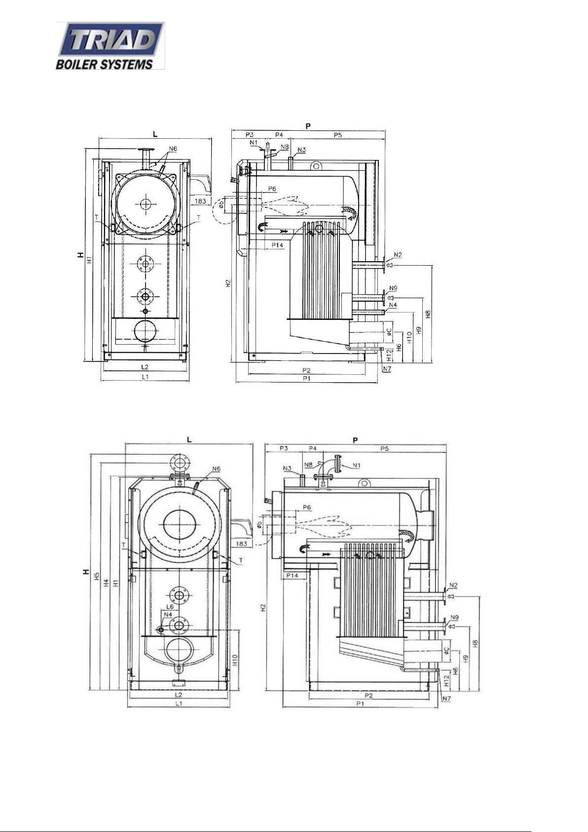
Model 300 & 500
Model 750 & 1000
20 TRIAD Boiler Systems, Inc.
West Chicago, IL
www.triadboiler.com

MODEL 1400 & 2000
N1 Boiler flow
N2 Medium temperature return
N3 Safety Valve fitting
N4 System filling/drainage
N5 Safety valve(s) fitting
N6 Immersion wells (not used)
N7 Boiler condensation drain
N8 Inspection well
N9 Low temperature return
T Inspection Plug
See Dimensions on next page.
21 TRIAD Boiler Systems, Inc.
West Chicago, IL
www.triadboiler.com
 Loading...