

Page 1
OmniCounter
OmniCounter
Wireless
Wireless
Infrared People Counter
Infrared People Counter
Model: OmniCounter
Model: OmniCounter
Traf-Sys/Walker Wireless, Inc | 190 Industry Drive – Pittsburgh, PA 15275 Page 1 of 9
Ph: 888-815-6568 | Fax: 928-222-7279 | www.trafsys.com
Introduction
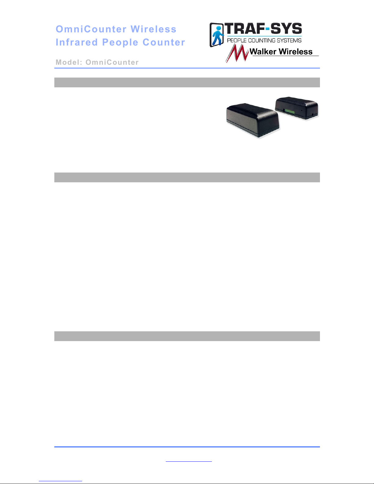
The Traf-Sys/Walker Wireless OmniCounter
Wireless Infrared People Counters provide a
simple and elegant, yet effective way to track foot
traffic through a given area or entrance. The
counter consists of two parts, a transmitter and
receiver, and determines traffic based using
infrared beam breaks; upon beam break, the LCD
counter will increment and the person will be
counted as having passed through your monitored
area/entrance.
Table of Contents
Introduction ......................................................................................................................... 1!
Table of Contents ................................................................................................................ 1!
Features and Benefits .......................................................................................................... 1!
Mounting and Orientation ................................................................................................... 2!
Side Firing Mode ............................................................................................................. 2!
Front Firing Mode ........................................................................................................... 3!
Dual (Directional) Mode ................................................................................................. 3!
Mounting Bracket ................................................................................................................ 4!
To Remove Sensor from bracket ......................................................................................... 5!
Configuration and Powering On ......................................................................................... 6!
Configuring the IR Receiver ........................................................................................... 6!
To display the counts on the LCD ................................................................................... 6!
Sending a Service Packet ................................................................................................ 7!
Troubleshooting .................................................................................................................. 7!
Appendix A: Battery Replacement ..................................................................................... 8!
OmniCounter Accessories ................................................................................................... 9!
Features and Benefits
• Infrared beam-interrupt 24-bit
People Counter
• Battery operated (fully wireless)
• Can operate in side-firing or front-
firing mode (switch selectable)
• Integrated 6 digit LCD display
indicating total counts
• Up to 20ft infrared transmission
range
• Complies with part 15 of the FCC
rules
• Up to 150ft (418MHz) indoor radio
transmission range
• Monitors infrared beam
interruptions and duration of beam
interruptions
• CRC-16 error checked radio
packets
• User replaceable batteries (3.6 volt
lithium)
• Flush mounting bracket (included
Page 2
OmniCounter
OmniCounter
Wireless
Wireless
Infrared People Counter
Infrared People Counter
Model: OmniCounter
Model: OmniCounter
Traf-Sys/Walker Wireless, Inc | 190 Industry Drive – Pittsburgh, PA 15275 Page 2 of 9
Ph: 888-815-6568 | Fax: 928-222-7279 | www.trafsys.com
Mounting and Orientation
One key to your OmniCounter People Counters operating properly and efficiently is their
mounting orientation and height; normal mounting height is between 36 and 52 inches.
Please see the illustrations below:
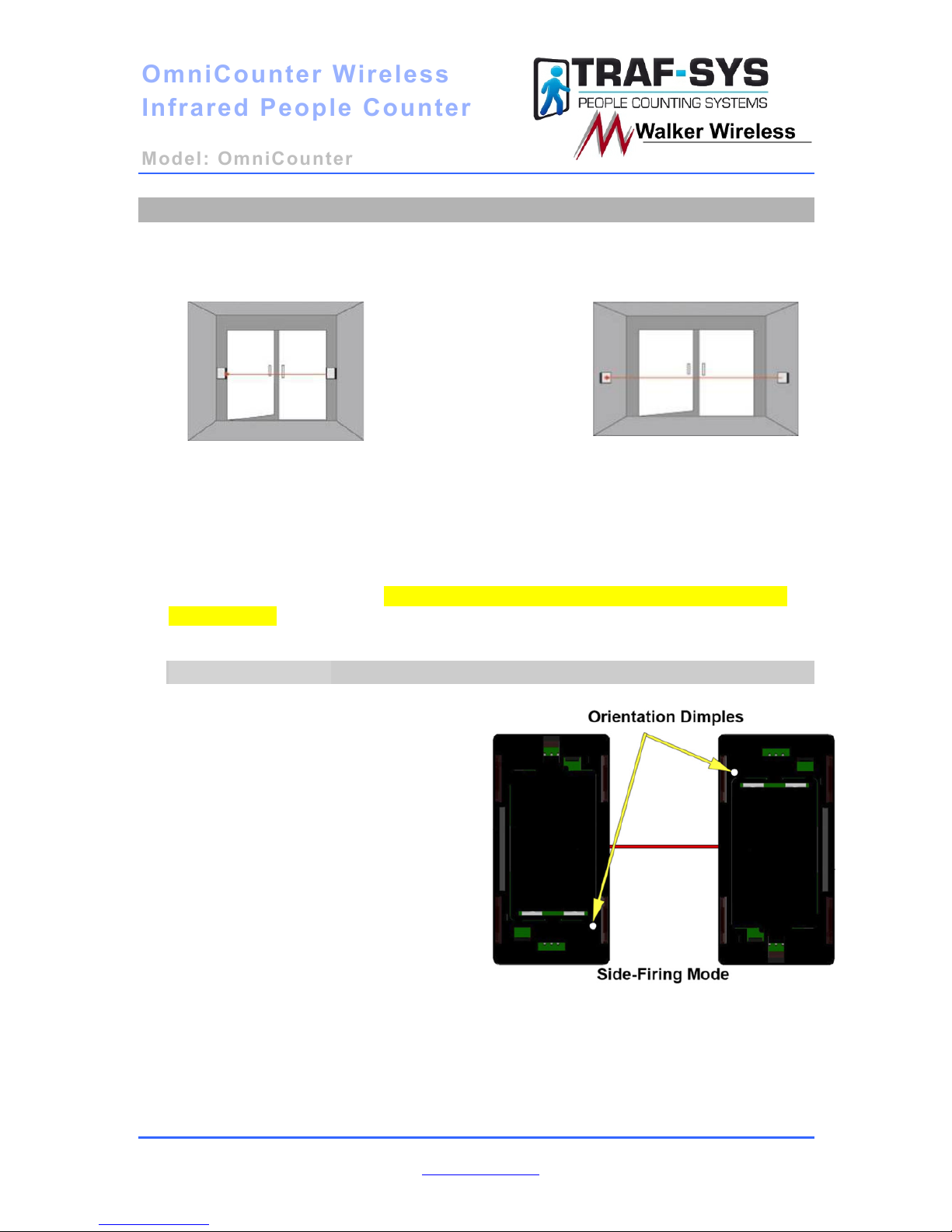
Figure 1
Figure 1 shows a typical side-
firing (door mounted)
installation.
Figure 2 shows a typical front-
firing (wall mounted)
installation.
Figure 2
Proper Orientation/Alignment is required for the counters to function properly.
Located on both the transmitter and receiver (LCD Display side) is a dimple that is
used to allow the correct orientation. The dimples are also used to indicate which
side of the enclosure the IR receiver or IR transmitter is located when using the
counter in Side-Firing Mode. The dimples have been painted white so they can be
located easily.
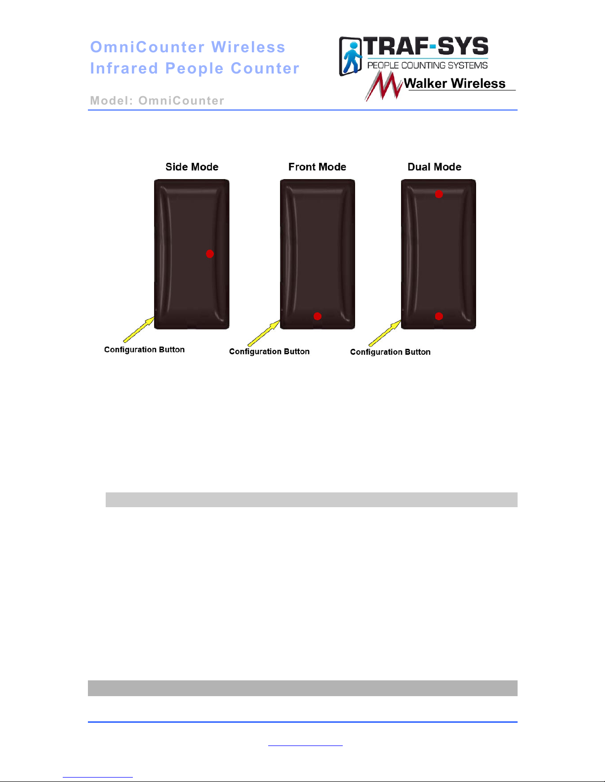
Side Firing Mode
In Side-Firing Mode, the counters need
to be mounted so that the dimples are
oriented to the center.
Page 3
OmniCounter
OmniCounter
Wireless
Wireless
Infrared People Counter
Infrared People Counter
Model: OmniCounter
Model: OmniCounter
Traf-Sys/Walker Wireless, Inc | 190 Industry Drive – Pittsburgh, PA 15275 Page 3 of 9
Ph: 888-815-6568 | Fax: 928-222-7279 | www.trafsys.com
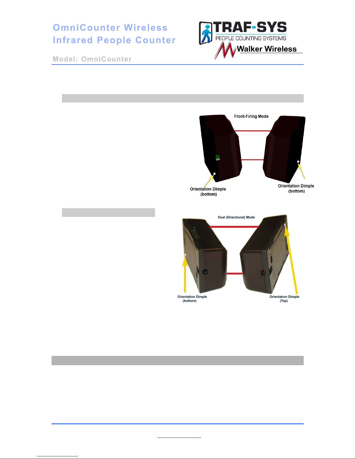
Front Firing Mode
When used in Front-Firing Mode, the
counter needs to be installed with either
both dimples at the top or both dimples at
the bottom.
Dual (Directional) Mode
For dual mode the receiver side
(side with the LCD display)
should be mounted horizontally
on the right side of the entrance
with the display facing up and
the dimple at the bottom. The
transmitter side is then mounted
horizontally with the dimple at
the top.
Page 4
OmniCounter
OmniCounter
Wireless
Wireless
Infrared People Counter
Infrared People Counter
Model: OmniCounter
Model: OmniCounter
Traf-Sys/Walker Wireless, Inc | 190 Industry Drive – Pittsburgh, PA 15275 Page 4 of 9
Ph: 888-815-6568 | Fax: 928-222-7279 | www.trafsys.com
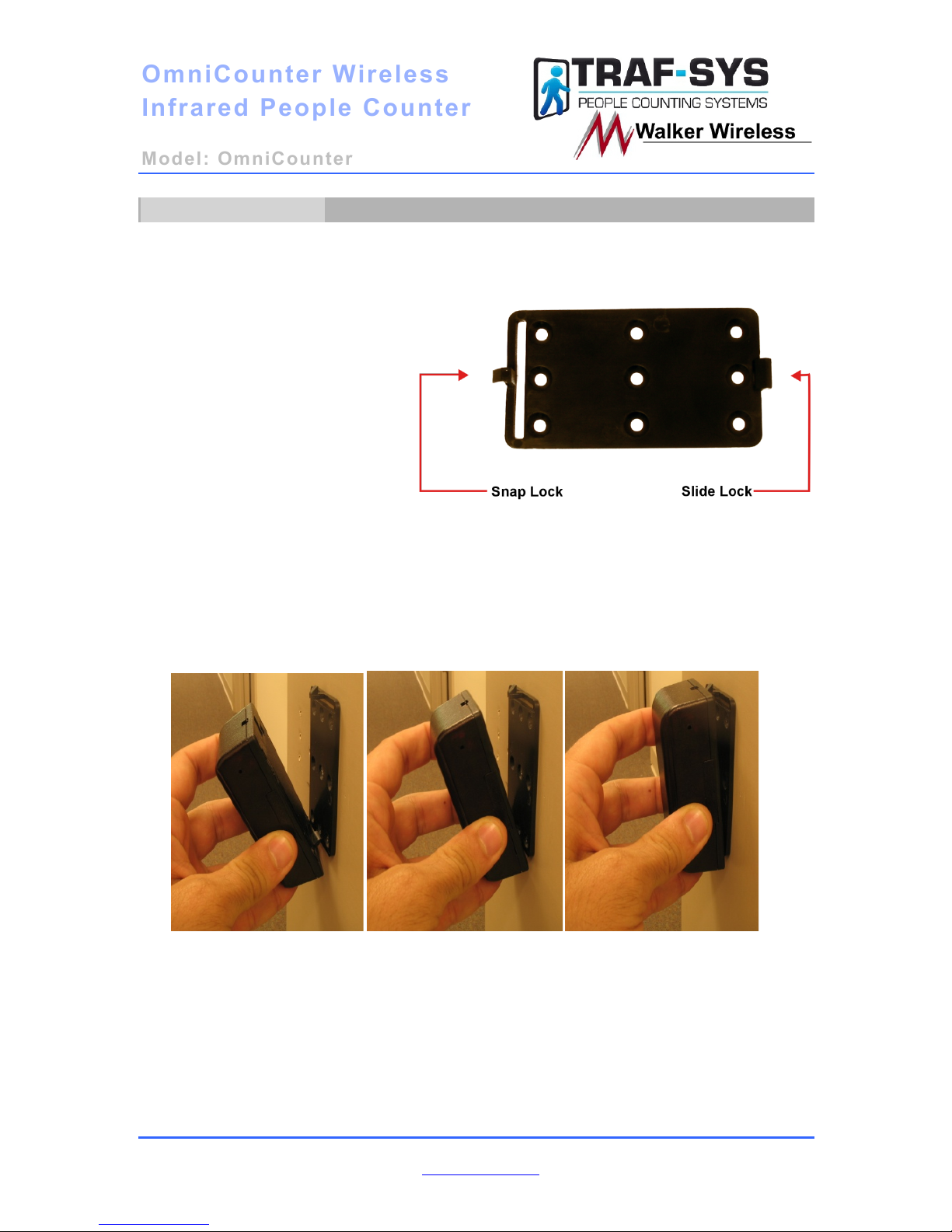
Mounting Bracket
You should decide what mode you are going to use your counters in before hanging
the mounting brackets. You will want to mount each mounting bracket (shown below)
with snap lock facing up for front firing mode to allow for proper orientation and
sensor operation. For side
firing the bracket will have
one snap lock facing up and
the other facing down to
allow for proper orientation
and sensor operation. For
dual (directional) mode the
brackets need to be mounted
horizontally. Both of the
brackets will have the snap
lock facing the inside of the
door to allow for proper
orientation and sensor operation.
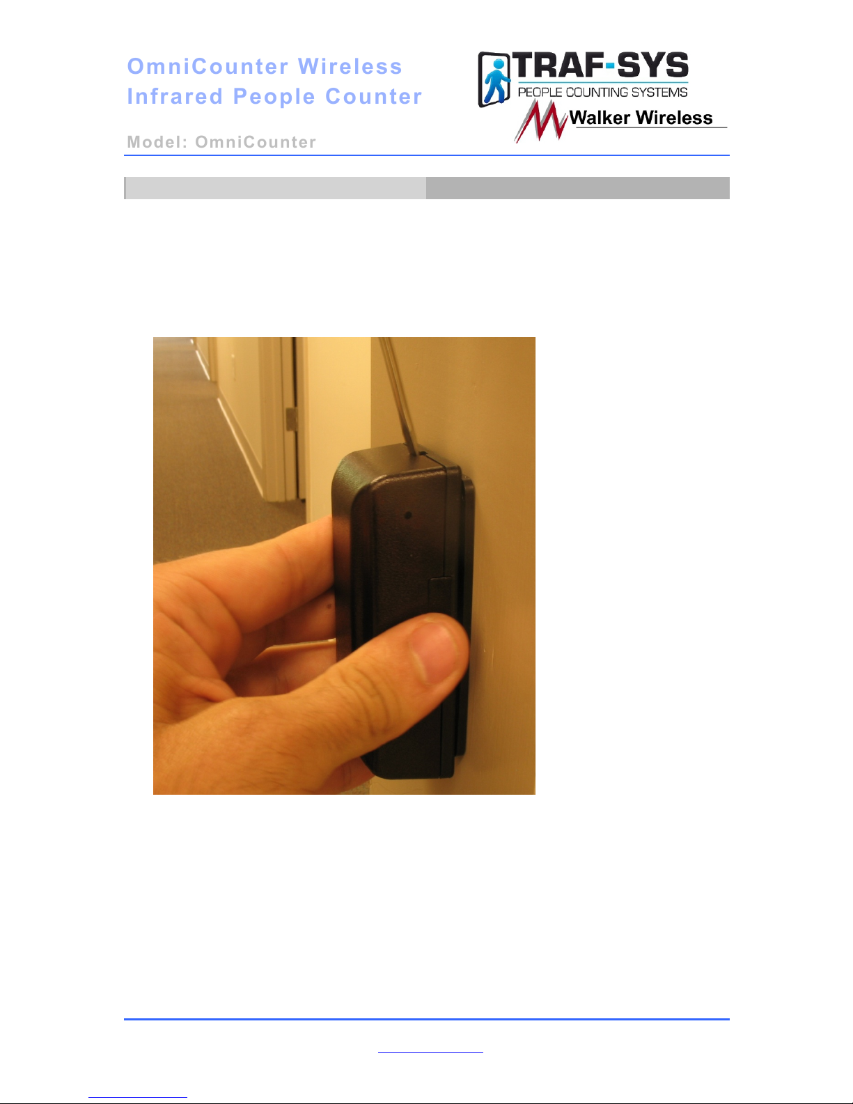
After mounting the brackets, your Omni Counter sensors simply slide onto the Slide
lock and then snap securely onto the Snap lock. The following guide will help
illustrate the process.
Figure 1 Figure 2 Figure 3
Figure 1: Grasp the sensor firmly and line it up with the Slide lock.
Figure 2: Slide the sensor onto the Slide lock.
Figure 3: Begin to push the sensor towards the Snap lock until it snaps into place.
Page 5
OmniCounter
OmniCounter
Wireless
Wireless
Infrared People Counter
Infrared People Counter
Model: OmniCounter
Model: OmniCounter
Traf-Sys/Walker Wireless, Inc | 190 Industry Drive – Pittsburgh, PA 15275 Page 5 of 9
Ph: 888-815-6568 | Fax: 928-222-7279 | www.trafsys.com
To Remove Sensor from bracket
To release the sensor from the mounting bracket, depress the Snap lock with the
included screwdriver and gently pull the top of the sensor away from the mounting
bracket. See Figure 4 below for the location of the Snap lock release.
Figure 4
Page 6
OmniCounter
OmniCounter
Wireless
Wireless
Infrared People Counter
Infrared People Counter
Model: OmniCounter
Model: OmniCounter
Traf-Sys/Walker Wireless, Inc | 190 Industry Drive – Pittsburgh, PA 15275 Page 6 of 9
Ph: 888-815-6568 | Fax: 928-222-7279 | www.trafsys.com
Configuration and Powering On
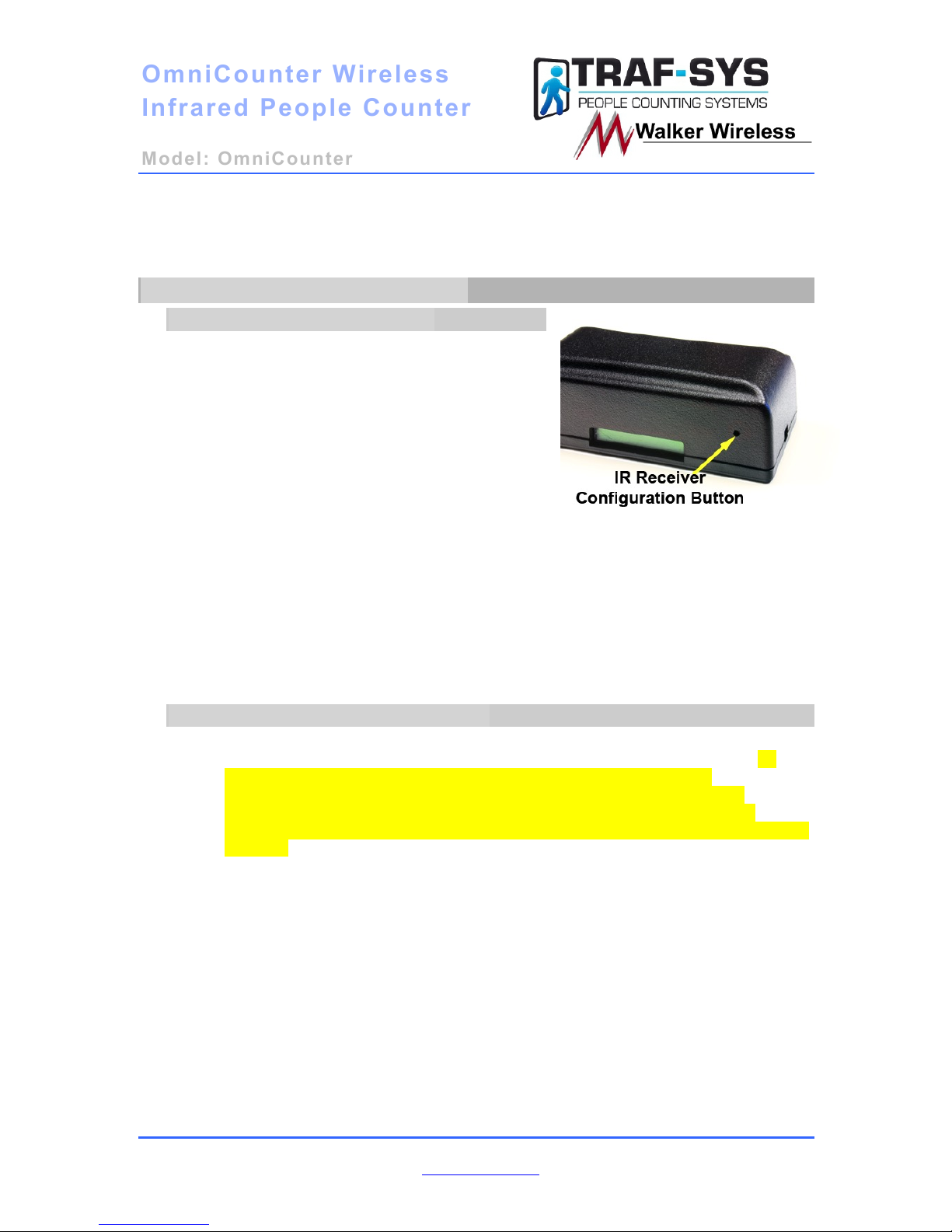
Configuring the IR Receiver
To turn the unit on or select the mode of
operation, use a paperclip to press and hold the
configuration button. The LCD display will
sequence through the available operation modes
of the SIDE, set FRNT, set DUAL, SELFTEST, or
PWR OFF. To select the desired mode, release
the button when the display indicates the mode.
To put the counter into Alignment Mode,
momentarily press and release the configuration
button on the IR Receiver. If the IR Receiver and
IR Transmitter are properly aligned, then the LED will be lit on the IR Receiver. You can
exit Alignment Mode by pressing the Configuration Button again or allow it to exit
Alignment Mode on its own (after 60 seconds). This button is also used to send a service
packet. This will be discussed later in the manual.
IR Range (Low Power) 0.5 Feet to 10 Feet
IR Range (High Power) 10 Feet to 20 Feet
To display the counts on the LCD
1.) Momentarily press the configuration button or 2.) Swipe a magnet across the IR
Receiver where the reed switch is located (opposite side of the LCD display). To
reset the counts to zero, hold a magnet next to the reed switch for
approximately 5 seconds. This is the only way to reset the counts. It is
recommended that you use your magnet to check your counts. This will
eliminate the potential of changing the configuration or possibly turning off the
sensors.
Page 7
OmniCounter
OmniCounter
Wireless
Wireless
Infrared People Counter
Infrared People Counter
Model: OmniCounter
Model: OmniCounter
Traf-Sys/Walker Wireless, Inc | 190 Industry Drive – Pittsburgh, PA 15275 Page 7 of 9
Ph: 888-815-6568 | Fax: 928-222-7279 | www.trafsys.com
Configuring the IR Transmitter
To select the mode of operation, use a paperclip to press and hold the configuration
button. The visible LED’s will provide feedback to the available modes (Side Low Power,
Side High Power, Front Low Power, Front High Power, Dual Low Power, or Dual High
Power). Low Power Mode is indicated by a solid LED and High Power Mode is indicated
by a flashing LED.
IR Range (Low Power) 0.5 Feet to 10 Feet
IR Range (High Power) 10 Feet to 20 Feet
Sending a Service Packet
Sending a service packet from the OmniCounter People Counters is a useful diagnostic
tool; it will allow you to do the following things:
1. It will allow you to easily add the sensor to your MIU data controller using the Auto
Add method described in your data controller’s manual.
2. It will automatically update the sensor’s status and make its total count visible. This is
most useful for retrieving your total count (standalone mode) or interactive monitoring
(when using a data controller).
To send a service packet, depress and release the service packet button using a small
pointed object (i.e. – paperclip, bobby pin).
Troubleshooting
Page 8

OmniCounter
OmniCounter
Wireless
Wireless
Infrared People Counter
Infrared People Counter
Model: OmniCounter
Model: OmniCounter
Traf-Sys/Walker Wireless, Inc | 190 Industry Drive – Pittsburgh, PA 15275 Page 8 of 9
Ph: 888-815-6568 | Fax: 928-222-7279 | www.trafsys.com
Below are solutions to common problems you may experience with the OmniCounter
Wireless Infrared People Counters.
My sensors are not counting.
The sensors are not generating counts when the infrared beam is being broken.
• Ensure the power is on for both sensors.
• Ensure that your sensors’ firing designation switch is set properly to be
front-firing or side-firing and ensure that the sensors are mounted to
match that designation.
• Your batteries may need replaced; see Appendix A for battery
replacement information.
I do not see any counts on my LCD screen.
The onboard screen displaying counts is blank.
• This is by design; sending a service packet or breaking the infrared beam
will cause the count total to become visible. This feature was
implemented to conserve battery life.
My sensor reads Blocked
Blocked status indicates that the receiver can’t see the transmitter. Therefore you
may need to check for these problems.
• Make sure that there is nothing in between the sensors that is blocking it
physically.
• Check the distance between the sensors. If they are approximately 12
feet apart make sure that the sensors are on high power.
• Make sure that the transmitter side is turned on.
• If batteries have been replaced with the 3.6V Lithium batteries, you will
need to turn the sensors back on.
Appendix A: Battery Replacement
When it comes time to replace the batteries in your sensors, please follow this quick
guide. You may purchase your batteries directly from Traf-Sys/Walker Wireless;
these sensors require 3.6 volt lithium batteries.
1. Remove the battery door on both of your sensors by applying pressure
downwards in the direction the arrow is pointing (towards the battery door as
show below in Figure 11).
2. Using your fingernails or the included screwdriver, gently pry and remove the
batteries.
3. Following the proper battery polarity designations (printed in white on the
circuit board under the batteries) replace the batteries with new 3.6 volt
lithium batteries.
4. Turn both units on and remount them on their brackets.
Page 9

OmniCounter
OmniCounter
Wireless
Wireless
Infrared People Counter
Infrared People Counter
Model: OmniCounter
Model: OmniCounter
Traf-Sys/Walker Wireless, Inc | 190 Industry Drive – Pittsburgh, PA 15275 Page 9 of 9
Ph: 888-815-6568 | Fax: 928-222-7279 | www.trafsys.com
5. Test your sensors by walking through the entrance or otherwise breaking the
beam path.
6. If your sensors successfully generated counts, congratulations, you have
successfully replaced the batteries in your sensors. If you were unable to
generate counters, please refer to the Troubleshooting section of this
document then contact Traf-Sys/Walker Wireless technical support if you
require further assistance.
Figure 11
OmniCounter Accessories
• MIU-1000 or CompuCount data controller
• 3.6 volt lithium AA battery
• Visicount server software (requires data controller)
• Traf-Sys Data Hosting and Support Services (requires data controller)
 Loading...