

Page 1
User’s Guide
MIU1500 / CompuCount
Wireless
Data Manager
MIU-1500 / CompuCount User’s Guide Page 1
Page 2

Contents
Introduction/Overview ........................................................................................................................................... 3
Models .................................................................................................................................................................. 3
Requirements ......................................................................................................................................................... 3
Getting Started ....................................................................................................................................................... 4
Hardware Setup ..................................................................................................................................................... 4
Changing Your PC’s Default IP Address ................................................................................................................ 5
Changing the Manager’s Default IP Address .......................................................................................................... 6
Changing the MIU’s Name .................................................................................................................................... 7
Adding Sensors ...................................................................................................................................................... 7
Viewing Counts ..................................................................................................................................................... 8
MIU Setup Options ................................................................................................................................................ 9
The Status Screen .................................................................................................................................................. 9
Sensor Setup ................................................................................................................................ ........................ 10
The MIU Setup Screen ........................................................................................................................................ 10
The Communications Setup Screen ...................................................................................................................... 11
Set Count Manager’s Clock ................................................................................................................................. 11
Passwords ............................................................................................................................................................ 12
Reset Options ...................................................................................................................................................... 13
Export Options..................................................................................................................................................... 14
Alternate Format .................................................................................................................................................. 17
Status of Sensors .................................................................................................................................................. 18
FTP Scripts .......................................................................................................................................................... 19
Common Software Tools ..................................................................................................................................... 20
Appendix ............................................................................................................................................................. 20
Specifications ...................................................................................................................................................... 21
Resetting the MIU-1500 to Factory Defaults ........................................................................................................ 22
Glossary of Terms ................................................................ ................................................................................ 23
MIU-1500 / CompuCount User’s Guide Page 2
Page 3

Introduction/Overview
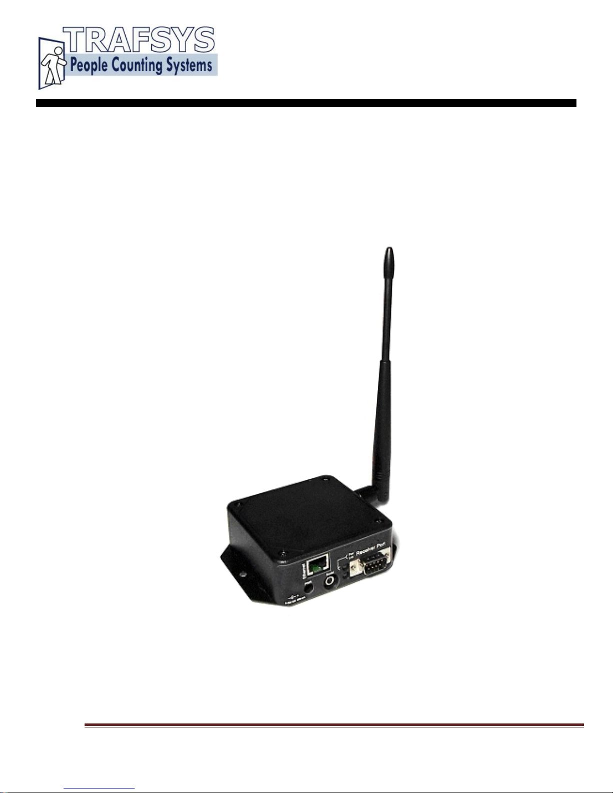
The new MIU-1500 is available with either an internal 418 Mhz receiver for smaller areas or an internal 900
Mhz receiver which will allow for greater distances. Additionally, the all new MIU-1500 unit also includes an
external RS232 serial port to add an optional external receiver.
The MIU-1500 Count Manager is designed to collect data from wireless counter sensors and display that data
through reports that can be viewed with an ordinary Web browser application.
The MIU-1500 gives reports of counts by half hour, hour, day, week and month. The MIU-1500 also makes this
same data available as text files downloadable using an FTP client program.
The MIU-1500 can manage up to 16 sensors. It can hold data for those 16 sensors for 3 months at 30
minute intervals, and for 1.5 years at day intervals.
Models
The new MIU-1500 is designed to work in conjunction with the following
Traf-Sys
Wireless counters:
Traf-Sys Directional Beam Sensors
Traf-Sys Single Beam Sensors
Traf-Sys Pulse Transmitters, used with Surround Sensor Sensors and Thermal Cameras
Requirements
•
The MIU-1500 with at least one counting sensor.
•
A
computer with an Ethernet card or network connection for TCP/IP communications.
•
A
Web browser application, such as Internet Explorer.
MIU-1500 / CompuCount User’s Guide Page 3
Page 4
Getting Started
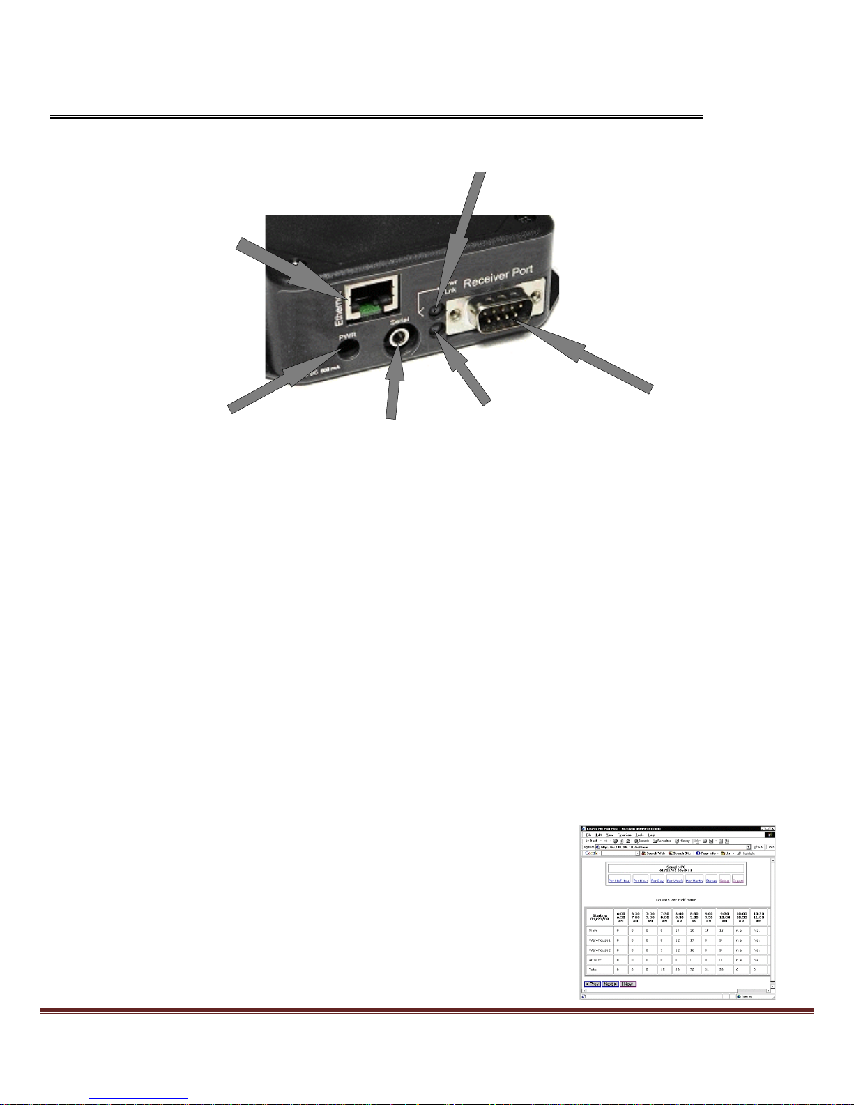
Hardware Setup
Power & Activity
Ethernet Port
Power Connection
Local Serial Port
Ethernet Link
Receiver Port
Apply Power
Plug the power supply into the MIU-1500 and make sure it is connected to a working outlet. The red power light will
come on when the
MIU is
plugged in.
The red light indicates that the MIU-1500 is functioning. The MIU-1500 also uses the red light to indicate
reception of a packet from a transmitter. The MIU-1500 will blink the red light momentarily indicating a packet
has been received and processed.
Connecting to PC
A crossover cable is included with the MIU-1500 setup. Plug the crossover cable into the Ethernet port on the
back of your computer and plug the other end into the Ethernet port on the MIU-1500. The Ethernet Link light
(green light) will turn on indicating a valid Ethernet physical connection.
Connecting to LAN
Alternatively you can connect the Manager to your Local Area Network. Your network administrator can help you
decide which IP address to assign to the Manager.
Testing the Connection
To check to see if you have made a connection, open your browser and type
in http://192.168.1.55.
The browser should display the MIU-1500 count
screen.
The screen will not show sensors until they are configured.
MIU-1500 / CompuCount User’s Guide Page 4
Page 5
Changing Your PC’s Default IP Address
If you have been unable to see the Manager's web page when connecting
directly to your PC, you may need to make changes to your computer's IP
configuration.
First, connect the
MIU
directly to the Ethernet port on the back of your
computer. Next, change the IP settings on your computer.
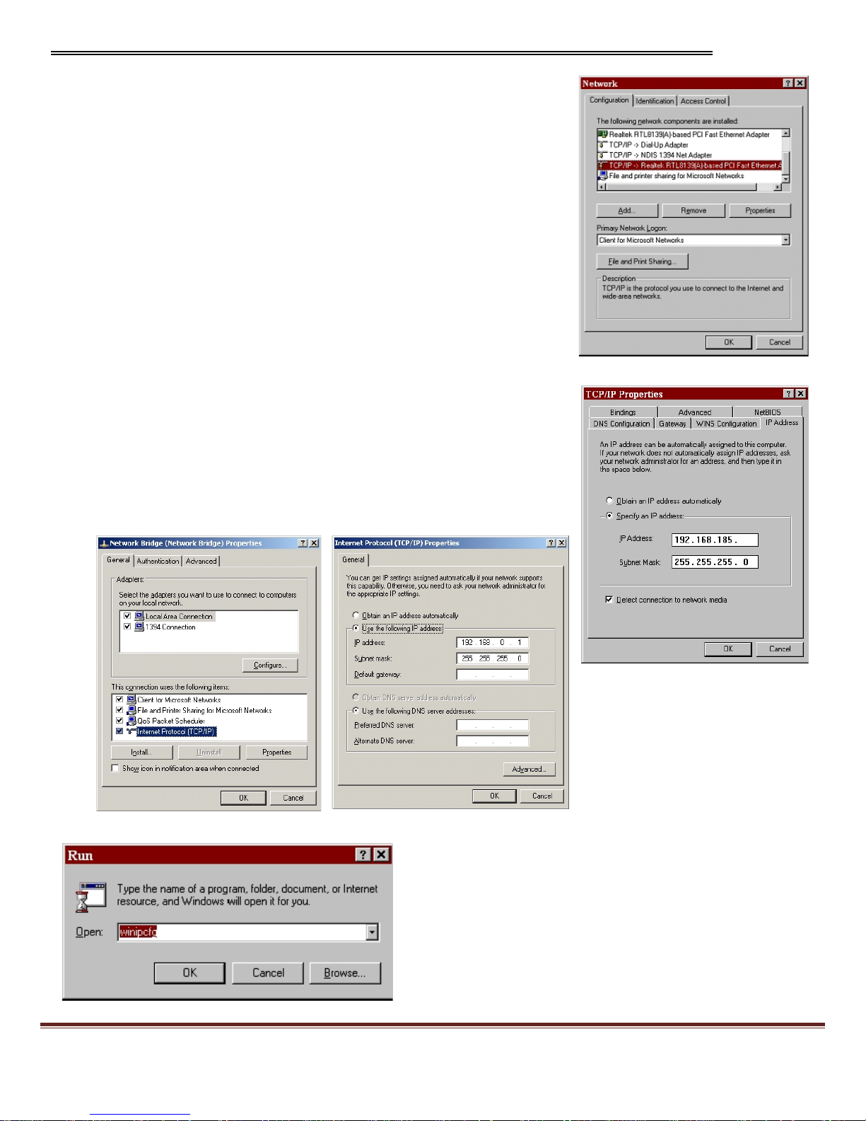
WINDOWS 95/98/ME/2000
To change the IP settings on a computer running the Windows
95/98/ME/2000, select the following: „Control Panel -> Network -> TCP/IP‟;
select the TCP/IP service for your network card; choose „Properties->IP
Address‟; choose „Specify an IP Address‟ (example: 192.168.1.40
255.255.255.0); and fill in the initial values for IP address and subnet mask.
With Windows 98 and ME you will need to restart the PC.
WINDOWS XP
WIN 95/98/ME/2000
To change the IP settings on a computer running Windows XP, select the
following: „Control Panel (if not already presented, you will find it easier to
„Switch to Classic View‟) -> Network Connections. Right-click on Local Area
Connection (or Network Bridge if installed) and select Properties. Highlight
„Internet Protocol (TCP/IP)‟ and click the Properties button. Select „Use the
following IP address‟ (example: 192.168.1.40
255.255.255.0) and fill in the
initial values for IP address and subnet mask.
WIN 95/98/ME/2000
WIN XP
WIN XP
Run WINIPCFG or IPCONFIG to verify changes.
When finished changing the IP address and connecting the
computer to the MIU-1500, use the Ping utility on your computer
(see the following section) and ping the MIU-1500 to verify your
settings and connection. A successful ping will receive a reply.
MIU-1500 / CompuCount User’s Guide Page 5
Page 6
Changing the Manager’s Default IP Address
In order for the MIU-1500 to communicate TCP/IP, it needs an IP address, network mask, and possibly a
gateway address. If you are connecting the Manager to your LAN, you should change the MIU-1500‟s defaults
(IP address 192.168.1.55; network mask 255.255.255.0; no gateway address and port 1000).
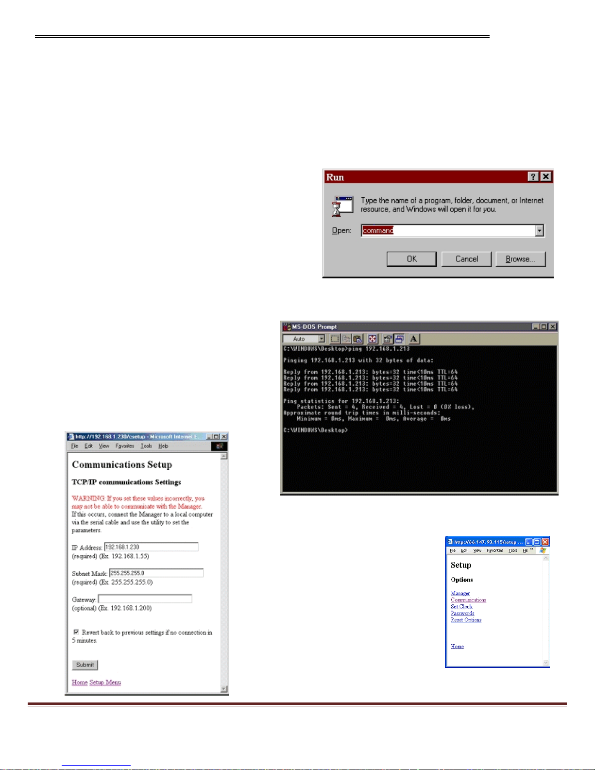
To change the IP address on the MIU-1500 go to the "Setup" link and then click on "Communications." There
you can enter a new IP address for the MIU-1500.
Before you change the IP address you should ping the new IP address to make sure that no computers on your
network have the IP address already. To ping, go to the
PC's "Start" menu, choose "Run" and in the "Open:" box
type "Command."
An MS-DOS window will appear. Type "Ping" and the IP
address you are trying to ping. If you want to change your
Manager's IP address to, say, 192.168.1.213 you would
type "Ping 192.168.1.213" and wait for a response. If the
result of the ping is "Request timed out" then there is no
other device on that IP address and you can safely change
the IP address of the MIU-1500.
Once you know the IP address you want, enter it into the "IP Address" box on the Communications Setup screen.
Enter the subnet mask also. You may need to
ask your network administrator for a subnet
mask. When you are ready, click the "Submit"
button at the bottom of the page. The program
will attempt to change the IP Address of the
MIU-1500. If successful, the browser will
redirect to the new IP address and at the
bottom of the screen, in green letters, it will say,
"Submission accepted. Parameters updated!"
Click on the link "Setup Menu" at the bottom of
the page to return to the Setup menu.
MIU-1500 / CompuCount User’s Guide Page 6
Page 7

Changing the MIU’s Name
Click on the "Manager" link of the setup menu.
From this page you can enter a name for the MIU-1500 Count Manager. You
can set the maximum amount of time that may pass between sensor
transmissions before the sensor is declared offline. You may set the
"Auto Add" mode for the MIU-1500.
The default "Auto Add" mode is "Service Mode."
"Service Mode" means the MIU-1500 will only add sensors to its list if it
receives a sensor packet that has been sent by pressing the Smart Switch on
the receiver (Traf-Sys
Wireless Beams) or
holding the magnetic wand at top
right facing corner of the unit (Pulse Transmitter).
"All" means that the MIU-1500 will add a new sensor any time it
receives a transmission from a sensor that is not already in its list.
"Off" means that the MIU-1500 will never add new sensors to its sensor
table.
Adding Sensors
The MIU-1500 Count Manager by default adds sensors to its configuration list when it receives a packet that has
been transmitted in "Service Mode." You can send a transmiss ion in service mode by pressing the Smart Switch on
the receiver (the unit with the LCD display - you will need to press this switch twice within 20 seconds)
of the counter sensor (Traf-Sys
Wireless Beams) or
holding the magnetic wand at top right facing corner of the
unit (Pulse Transmitter).
CAUTION: If you are adding a MIU-1500 to an existing counter setup, this will erase all counts.
The MIU-1500 will add counters to its configuration and you may view their data from the main browser screen.
You may need to refresh the screen a couple of times before the counter shows up.
Once you are finished adding counters, return to the Manager‟s Setup screen and turn the „Automatically add
sensors‟ selection to “Off.”
MIU-1500 / CompuCount User’s Guide Page 7
Page 8
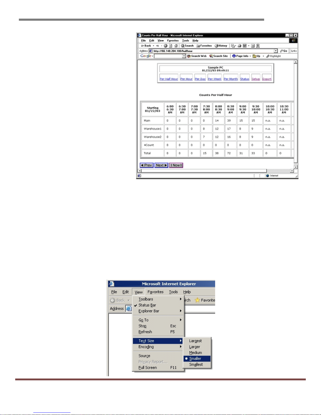
Viewing Counts
To view the current sensors and their
data, start your browser and enter the
Manager's IP address in the "Address:"
box.
The user can view the count total at
different time granularities. The user can
view counts summed per Half Hour, per
Hour, per Day, per Week, or Per Month.
Clicking on the links at the top of the
screen will change the time granularity.
The user can also navigate through count
history by using the "Prev" and "Next"
buttons at the bottom of the screen.
Clicking the "Now" button will take you to
the current date and time. If counts have
been recorded for the current view, they
will be displayed. Otherwise (for example,
if the requested view is in the future, or a
time earlier than the first sensor
transmission) the cell for that time period
will display "n.a." (for "not applicable").
Each configured sensor has a row in the table. Directional counters show counts on two lines for Count A and
Count B. The total of all counts for all sensors for that time period will be displayed on the bottom row of the table
and the right hand column.
For all time intervals greater than Half Hour, the top row of the table contains links to focus in on a smaller time
interval. For example from the "Per Month" view you can click on a specific month, like January, in order to see
the weekly breakdown of counts for January.
To get the latest data, click the "Now" button or click the "Refresh" button on the browser.
The date and time on the display show the time the report was generated.
You can make the table appear smaller if you want it to fit on the screen better by (in Internet Explorer) going to:
View | Text Size | Smaller.
MIU-1500 / CompuCount User’s Guide Page 8
Page 9

Error Message
Description
Offline
The
MIU h
asn't received a transmission from
this sensor within the timeout interval, which is
set in the "Manager Setup" screen under
"Sensor Offline Time."
Beam Blocked
The sensor beam seems to be blocked by some
obstruction.
Check Battery
The battery voltage is low or the battery is not
present.
No Line Power
Line power has been removed or is too low.
MIU Setup Options
The Status Screen
The status screen shows detailed information about
the sensors currently being monitored. To view the
status screen click on the "Status" link from the main
screen.
The status table shows, for each sensor, the
identifying label name of the sensor ("Sensor") , the
serial number of the sensor ("ID"), the number of
seconds elapsed since the last transmission ("Age"),
whether the last transmission was sent in service
mode or not ("Srv"), and the data value of the last
reading ("Last Reading").
The last reading is the accumulated count of the sensor since the sensor started or
since the last reset.
If
the transmission was sent in service mode, there will be an "X" in the "Srv" column.
When the MIU-1500 receives a transmission from a new sensor it assigns it a default label which is the sensor
position plus the sensor type ("1Count"). You can change the label assigned to the sensor by clicking on the label
name in the "Sensor" column.
The status table will highlight in yellow a row in the table if the sensor is in an error state. The browser will show
an error message when the mouse pointer is moved over top of the graphic symbol. The following table shows
the possible error states:
MIU-1500 / CompuCount User’s Guide Page 9
Page 10

Sensor Setup
Reverse A and B
MIU-1500 presents the
"Reverse A and B" checkbox if the
counter is a Directional Counter. If checked, the MIU-1500 will
switch the "A" and "B" counts of the Directional Counter
allowing the user to assign A and B to incoming and outgoing traffic
as desired.
Changing the Sensor's Name
Type a new name in the "Sensor Name" box.
Deleting a Sensor
The very last sensor in the table on the status screen can be
deleted. Click the "Delete Sensor" box and hit the "Submit" button.
Replacing a Sensor
If you want to swap out a sensor but keep the new sensor in the
same position as the old one, simply go to the sensor setup screen
for the sensor you want to replace and type in the new sensor's
serial number in the "Serial No." box. Hit the "Submit" button and
the MIU-1500 will update its configuration with the new sensor
information. As always, enter the serial number with care!
The MIU Setup Screen
The setup screen allows you to set some parameters for the MIU-
1500. You can change the name of the MIU-1500. Note: the Manager
Name is also used as the Login User Name when passwords have
been set up.
"Sensor Offline Time" allows you can set the amount of time that can
elapse between transmissions from one sensor before the sensor is
declared offline.
You can set the "Auto Add" mode on the Manager. The "Auto Add"
mode tells the Manager what to do when it receives a transmission
from a sensor that is not already in the Manager's sensor table.
If
"Auto Add" is "Off" then the Manager will ignore all transmissions from
sensors that are not in the table already. If "Auto Add" is "All", the
Manager will add a new sensor to the sensor table each time it
receives a transmission from a new sensor. If "Auto Add" is "Service
Mode" then the Manager will only add a new sensor to the table if the
transmission is received in service mode.
When you are ready to make changes, press the "Submit" button.
Click the "Home" link to see the table of counts and click the "Setup
Menu" to go back to the setup menu.
MIU-1500 / CompuCount User’s Guide Page 10
Page 11

The Communications Setup Screen
The communications setup screen allows you to change the MIU-1500's
IP address, subnet mask, and gateway. Enter these parameters as
necessary and click "Submit." The new parameters are sent to the MIU1500 and an intermediate screen displays.
If the IP address is changed successfully, the browser will redirect itself to
the new IP address and there will be a message on the screen saying,
"Submission accepted! Parameters updated."
If the change of IP address was not successful, you will see a browser
error page telling you that the file cannot be found.
If you check the box that says, "Revert back to previous settings if no
connection in 5 minutes" then the program will try to update the
Manager's IP address. If it cannot make a connection within 5 minutes
thereafter, it will reset the IP address to the previous settings.
Set Count Manager’s Clock
You will need to make sure the Manager's clock is set correctly so that it can display the counts and totals
correctly. Choose "Set Clock" from the Setup menu, enter the correct values, and click "Submit" to set the
MIU-1500's clock.
If you set the clock back more than 30 minutes the Manager will require you to reset the counts before updating
the clock.
If
you set the clock ahead more than 30 minutes the Manager will pad the log with zeroes (0) for the
counts for those times.
MIU-1500 / CompuCount User’s Guide Page 11
Page 12

Passwords
Count Manager controls access to the different resources of the MIU1500 through passwords. There are two levels of Login access for
the MIU-1500: Report and Setup. Through the Report Login, the
MIU-1500 allows access to the data portions of the MIU-1500 like the
HTML reports and FTP download files. Through the Setup Login, the
user can make changes to the MIU-1500 setup. With the Setup
Login, the user has all the rights of the Report Login as well. If the
Login password has been configured and the user has not logged in
yet, the MIU-1500 will respond with an error message to commands.
If you set up a password to restrict viewing ("Report Password") then
changing the setup will be restricted also. If you set up a password
for setup ("Setup Password") without setting the “Report Password”
then viewing of reports is not restricted.
When you enter a password, the characters will be masked with
asterisks. You type "cat" and the box will show "***". It is very
important that you remember your password.
Click "Submit" to establish password protection in the
MIU-1500.
After passwords are established, you will encounter a screen
requesting a password when attempting to perform an action that is password protected.
The screen will ask for a
user name. For access to the reports (HTML and FTP) the user name is “Report”. For access to the setup, the
user name is the name of the MIU-1500.
Note: For FTP, if a Report password is set, use the Report password and 'FTP' as the User Name and use an
FTP client program to collect the data, otherwise use "anonymous" to login.
WARNING: User Name and Password are case
sensitive. Do not use special characters like spaces
in the password. Please use caution when entering
a new password. If you forget your password, you
WILL need to clear the memory on the unit.
MIU-1500 / CompuCount User’s Guide Page 12
Page 13

Reset Options
Be careful when you reset values. There is no way to undo these changes.
On the reset screen you may select to reset the sensor counts to zero ("Reset Counts"), delete all the sensors
from MIU-1500's setup table ("Delete All Sensors") or reset the People MIU-1500 to factory settings
("Reset People MIU-1500").
Resetting the MIU-1500 to factory settings will reset the IP address back to the default 192.168.1.55. The browser
will not redirect itself and you will need to re-enter the IP address into the "Address" bar.
MIU-1500 / CompuCount User’s Guide Page 13
Page 14

Export Options
Viewing
From the main screen click on the "Export" link. You will be brought to the reports
section. From here you can view and save data in text format.
You may also
right-click with your mouse on the link. A menu will pop up. If you choose "Save
Target As…" you can use the resulting Save dialog box to save the counts report to
a text file on your computer. You can view these files with any text editor.
You also view a directory of the available files using the Manager‟s IP address in
the URL. Example: ftp://192.168.1.55
There are two file formats. The Standard Format is more compact and provides
counts for all sensors for the period on each line. The Alternate Format provides a
count per line, per sensor , per period.
The files have a title based on the time span of the report plus a timestamp. An
example title is this: "CNT24-012003103434.txt”
This is the count file for the last 24 hours and the report was generated on 01/20/03
at 10:34:34 a.m.
The following is table of the available files:
Web Page Title File Name Short File Name
Standard Format
Counts for the last full day until the
present time (counter per 30 minutes)
Counts for the last 7 full days until the
present time (counter per 30 minutes)
Counts for the last 31 full days until
the present time (counter per 30
minutes)
All Counts for the day Log (counts per
day)
Alternate Format
Counts for the last full day until the
present time (counter per 30 minutes)
Counts for the last 7 full days until the
present time (counter per 30 minutes)
Counts for the last 31 full days until
the present time (counter per 30
minutes)
All Counts for the day Log (counts per
day)
Status
CNTDAY-timestamp.txt CNTDAY.txt
CNT7DAYS-timestamp.txt CNT7DAYS.txt
CNT31DAYS-timestamp.txt CNT31DAYS.txt
CNTPERALL-timestamp.txt CNTPERALL.txt
REC24-timestamp.txt REC24.txt
REC7-timestamp.txt REC7.txt
REC31-timestamp.txt REC31.txt
RECPERALL-timestamp.txt RECPERALL.txt
Status of sensors STATUS-timestamp.txt STATUS.txt
The short file name can be used to get the most current file.
If no Report Password is set, you can use an FTP client program or Windows Internet Explorer to obtain the data.
Use “anonymous” for the user name.
If the Report Password has been set, you will need to use an FTP client program to download the reports.
You will not be able to use Windows Internet Explorer to obtain this data. There is an interaction problem
between the MIU-1500 and Windows Internet Explorer using FTP when passwords are set. The user name
is the name of the Manager and the password is the report level password.
MIU-1500 / CompuCount User’s Guide Page 14
Page 15

Viewing
- continued
Standard Format
There are eight different kinds of record types. Each record starts with a number that tells what kind of record it is.
Manager Counter Information
0, date, time, Manager name, mac, number of sensors, setup timestamp, report start, report finish
Where:
date
–
date that the report was generated.
time
–
time that the report was generated.
Manager name
–
name of the MIU-1500.
mac
–
MAC address of the Manager.
number of sensors
–
the number of sensors currently being monitored.
setup timestamp
–
the time stamp of the last setup change.
report start
–
the time and date of when the report starts.
report finish
–
the time and date of when the report finishes.
Sample record: 0,01/20/03,14:36:02,Sample PC,00:90:C2:C1:0F:D9,2,01/20/03 13:10:17,01/17/03
00:00:00,01/20/03 14:36:01
Sensor Names
1, date, time, sensor name1,…sensor namen
date
–
date that the report was generated.
time
–
time that the report was generated.
sensor name
–
name of the sensor
n
–
number of sensors
Sample record: 1,01/20/03,14:36:02,Main,Warehouse1
Sensor Serial Numbers
2, date, time, serial number1,…serial numbern
date
–
date that the report was generated.
time
–
time that the report was generated.
serial number
–
serial number of the sensor.
n
–
number of sensors
Sample record: 2,01/20/03,14:36:02,0000000000608220,000000001C110321
MIU-1500 / CompuCount User’s Guide Page 15
Page 16

Viewing
- continued
Sensor Types
*3, date, time, sensor type1, …sensor typen
date
–
date that the report was generated.
time
–
time that the report was generated.
sensor type
–
type of sensor: 1
–
Traf-Sys Peoplecounter; 2
–
Mighty-Might or Directional
Counter
n
–
number of sensors
Sensor Period A Counts
7, date, time, countA1, …countAn
date
–
date of the period.
time
–
time of the period.
countA
–
count for the period for the first set of counts for the sensor. The period is either 30
minutes or 1 day
n
–
number of sensors
Sample record: 7,01/17/03,00:00:00,127,115
Sensor Current Interval A Counts
8, date, time, countA1, …countAn
date
–
date of the current interval.. This is a partial total for the interval, as the current interval has
not been completed yet.
time
–
time of the current interval.. This is a partial total for the interval, as the current interval has
not been completed yet.
countA
–
count for the current interval for the first set of counts for the sensor.
n
–
number of sensors
Sample record: 8,01/20/03,00:00:00,176,147,142,1,3,353
Sensor Period B Counts
*9, date, time, countB1, …countBn
date
–
date of the period.
time
–
time of the period.
countB
–
count for the period for the second set of counts for the sensor.. The period is either 30
minutes or 1 day
n
–
number of sensors
MIU-1500 / CompuCount User’s Guide Page 16
Page 17

Viewing
- continued
Sensor Current Interval B Counts
*10, date, time, countB1, …countBn
date
–
date of the current interval.. This is a partial total for the interval, as the current interval has
not been completed yet.
time
–
time of the current interval.. This is a partial total for the interval, as the current interval has
not been completed yet.
countB
–
count for the current interval for the second set of counts for the sensor.
n
–
number of sensors
* These records are only included if a Directional Counter is in the sensor list.
Alternate Format
Header Record
The first record of every file is a header that has titles for every column. The following is an example:
"Type","Manager Name","MAC","Sensor Name","Serial No","Sensor Type","Start Time","End Time","Count
A","Count B"
Data Record
Type
–
type of record: 1
–
record contains counts for the full period; 5
–
record contains counts for a
partial period ( the current period which is incomplete).
Sever Name
–
name given to the Manager
MAC
–
serial number of the Manager (the ethernet MAC address)
Sensor Name
–
name given to the sensor
Serial No
– 16
character serial number of the sensor
Sensor Type
– 1 –
Traf-Sys Peoplecounter; 2
–
Mighty-Might or Directional Counter
Start Time
–
starting date and time of the period
End Time
–
ending date and time of the period. For record type 5 this time will be less than the
full period.
Count A
–
count for the period
Count B
–
count for the period. Will always be 0 for Sensor Type 1.
MIU-1500 / CompuCount User’s Guide Page 17
Page 18

Viewing
- continued
Status of Sensors
Header Record
The first record of the file is a header that has titles for every column. The following is an example:
"Manager Name","MAC","Sensor Name","Serial No","Sensor Type","Time","Age","State",”Count A”,"Count
B" Data Record
Manager Name
–
name given to the MIU-1500
MAC
–
serial number of the Manager (the ethernet MAC address)
Sensor Name
–
name given to the sensor
Serial No
– 16
character serial number of the sensor
Sensor Type
– 1 –
Traf-Sys People counter; 2 – Directional Counter
Time
–
time when the report was generated.
Count A
–
accumulated count since the counter started or was reset
Count B
–
accumulated count since the counter started or was reset. Will always be 0 for Sensor
Type 1.
Standard Format
Alternate Format
MIU-1500 / CompuCount User’s Guide Page 18
Page 19

FTP Scripts
You may need to create scripts in Windows to automatically download files from the MIU-1500. The following
is an example of an ftp script and batch file that you can use for this purpose:
You will need two files to automatically download from the MIU-1500. The first is a batch file and the second is
an ftp script file that will be run by the batch file.
Batch File
ftp –s:download30MinFile.scr 192.168.1.55
The example below shows the command you would use to create a batch file. This command will run a ftp
script file named
download30MinFile.scr
and connect to a MIU-1500 device at 192.168.1.55. Create a new
text file with the contents below and save it as download.bat
FTP Script File
The example below shows the commands you would use to create a ftp script file. This script will login to the
ftp interface of the MIU-1500 and download the RECPERALL.txt file to the current directory. Make sure you
specify the ftp user name and password in the script to connect successfully. To use this with the batch file,
make sure you name the file
download30MinFile.scr.
ftpUser
ftpPassword
get RECPERALL.txt
bye
Running the Batch
You should now have two files, download.bat and download30MinFile.scr. In windows, run the download.bat
file. This will connect to the MIU-1500 and run the ftp script which will download the RECPERALL.txt file. If you
need to schedule this batch, you can do so using Windows Task Scheduler.
MIU-1500 / CompuCount User’s Guide Page 19
Page 20

Appendix
Common Software Tools
The interface to the MIU-1500 was designed to meet common standards and be easy to use. You can use
common software that either comes with your operating system or can be purchased to diagnose common
problems and to communicate with the MIU-1500.
The primary means of obtaining the MIU-1500 reports is use a Web Browser and you download report files using
an FTP client.
The MIU-1500 has a command / response protocol that can be used with serial, radio and TCP/IP medias. For
TCP/IP you send simple text commands via port 1000 (default) and receive responses. The commands are used
to set up the MIU-1500 and to diagnose problems. You can use a communication program that has terminal
emulation to get familiar with the MIU-1500 commands and communications. Once you are familiar with the
commands, you can automate the communications using common development programming languages.
Here are some examples of common software:
Microsoft Windows
Internet Explorer
–
used to view the reports and set up the MIU-1500
FTP
–
command line utility that allows you download the report files
Third party FTP Clients
–
commercial and shareware FTP client programs used to download the report
files
Ping
–
simple program to test the TCP/IP connection.
Telnet
–
simple program to send commands and see responses via TCP/IP. Note: MIU-1500 uses port
1000 as default.
Winipcfg
–
utility that shows the computer‟s IP address.
Ipconfig
–
utility that shows the computer‟s IP address (DOS program).
HyperTerminal
–
provides terminal emulation program to communicate via TCP/IP, and serial port. Note:
HyperTerminal can answer calls via TCP/IP but does not work very well with the MIU-1500 in this mode
because HyperTerminal echoes characters it receives.
Procomm
–
third party program from Symantec
–
provides terminal emulation to communicate via TCP/IP
and serial port.
Other Operating Systems
Web Browser
–
used to view the reports and set up the MIU-1500
FTP
–
command line utility that allows you download the report files
Third party FTP Clients
–
commercial and shareware FTP client programs used to download the report
files Ping
–
simple program to test the TCP/IP connection.
Telnet
–
simple program to send commands and see responses via TCP/IP. Note: MIU-1500 uses port
1000 as default.
MIU-1500 / CompuCount User’s Guide Page 20
Page 21

Specifications
Parameter
Value
Power Supply Voltage
6 to 12
volts
Power Supply Current
250 milliamps
Receiver Frequency
418, 422 or 900 MHz or 2.4 GHz
Ethernet
10BaseT (10 MHz / 1.2 MHz effective rate)
Serial Port
19200 baud, no parity, 8 data bits, 1 stop bit
Battery
3
Volt Lithium CR2032
Backup of the SRAM & real time clock: 6 years
without power
30 Minute Log
3
months
Day Log
1
year, 7 months
Number of Sensors
16
MIU-1500 / CompuCount User’s Guide Page 21
Page 22

Resetting the MIU-1500 to Factory Defaults
Warning: this procedure will clear any data stored on the MIU-1500.
On each MIU-1500, there is a reset button you can use to reset the memory back to the factory
defaults. You should use a paperclip to reach the reset button from the outside of the case.
Depending on the version of your MIU-1500, the reset switch can be located in different locations
on your MIU-1500. The reset switch will be a small hole just large enough for a paperclip located
near the antenna. Here are some photo examples.
Figure 1
Figure 2
MIU-1500 / CompuCount User’s Guide Page 22
Page 23

Figure 3
Insert the paperclip into the reset switch access. You should be able to depress a button under the
access hole. On some versions, the switch may be difficult to access. The switch
in Figure 2 is particularly difficult to reach as the switch is deep beneath the case.
You will need to feel around with the paperclip until you reach a button, or
remove the top of the case.
With the paperclip inserted, you should be able to depress a button inside the
case. Hold the button down with the paperclip, while plugging in the power
adapter to the MIU-1500. When you plug in the power adapter, the red Power
indicator should flash on and off. If the power indicator does not flash on and off,
remove the power adapter and make sure you are depressing the reset button.
Release the button and the red power indicator should turn off for a few seconds, and then appear on.
The MIU-1500 is now set to the factory default settings and should have the following network settings:
IP Address: 192.168.1.55
Subnet Mask: 255.255.255.0
MIU-1500 / CompuCount User’s Guide Page 23
Page 24

Glossary of Terms
Auto Add Mode - When in this mode, the MIU-1500 receives sensor information from a sensor and then
automatically appends the sensor to the sensor table with default setup information.
CRC-16 Error-Checking - An algorithm designed to check for errors in a data stream.
Ethernet - The physical and electrical interface for connecting computers together on a network.
FTP - TCP/IP protocol design to transfer files.
HTML - HyperText Markup Language - fundamental language used in creating web pages.
Inactivity Timeout - The amount of time the MIU-1500 will wait for a command before terminating the
connection.
Inactivity Timeout applies to Ethernet connections.
For the local serial port, MIU-1500 will
automatically log out a user if a command is not received within this time.
IP Address - 32 bit address usually represented as a series of 4 numbers that uniquely identifies a device that is
using the TCP/IP protocol.
ISP - Internet Service Provider - provides the means to interfacing to the Internet.
MAC - The MAC address is permanently part of the MIU-1500 cannot be changed and is unique for all
Ethernet interfaces.
Ping - TCP/IP diagnostic utility used to determine if connection with another TCP/IP host is possible.
RS232 - Standard electrical interface used for serial ports.
Sensor - wireless transmitter
Sensor Age - The amount of time since the MIU-1500 has received a data packet from the sensor.
Sensor Table - Each row in the sensor table contains the a sensor's current readings, event states and setup
information. Commands either read or set information to and from the sensor table.
Service - Transmitters have a Service button that when pressed forces the sensor to transmit its readings.
TCP/IP - Main protocol used to transport data across the Ethernet and Internet.
MIU-1500 / CompuCount User’s Guide Page 24
 Loading...