

Page 1
X
10-6030/31: TrafiCam - revision R6.00
TI (9 wires) - revision R2.00
TrafiCam PC Tool - version V2.03
TrafiCam firmware - version V2.10
TrafiCam with TI (9 wires)
Manual release: May 2009
User guide
T
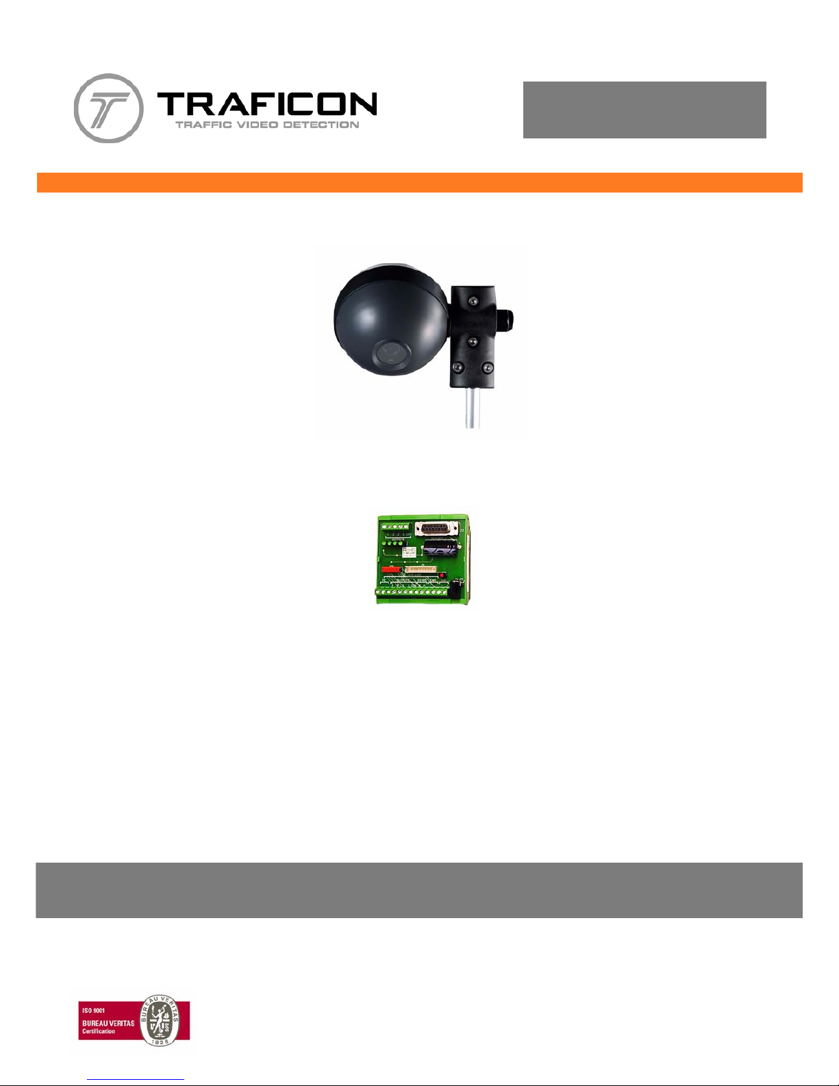
TrafiCam
TI (9 wires)
Page 2

iWX
TrafiCam with TI (9 wires)
Safety warning
EN55022
FCC Part 15
Warning
This is a class A product. In a domestic environment this product may cause radio interference in which case the user
may be required to take adequate measures.
This device complies with part 15 of the FCC Rules. Operation is subject to the following two conditions: (1) This
device may not cause harmful interference, and (2) this device must accept any interference.
Note: This equipment has been tested and found to comply with the limits for a Class A digital device, pursuant to part
15 of the FCC Rules. These limits are designed to provide reasonable protection against harmful interference w hen
the equipment is operated in a commercial environment. This equipment generates, uses, and can radiate radio
frequency energy and, if not installed and used in accordance with the instruction manual, may cause harmful
interference to radio communications. Operation of this equipment in a residential area is likely to cause harmful
interference in which case the user will be required to correct the interference at his own expense.
Modifications not expressly approved by the manufacturer could void the use r's authority to operate the equipment
under FCC rules.
Page 3

iiWX
TrafiCam with TI (9 wires)
Notice
The information contained in this document is subject to change without notice.
Traficon n.v. makes no warranty of any kind with regard to this material, including, but not limited to, the implied
warranties of merchantability and fitness for a particular purpose.
Traficon n.v. shall not be liable for errors contained herein or for incidental or consequential damages in connection
with the furnishing, performance, or use of this material.
No part of this document may be copied, reproduced, or translated to another language without the prior written
consent of Traficon n.v.
Copyright © 2009 , Traficon n.v. - All rights reserved
Traficon n.v.
Vlamingstraat 19
B-8560 Wevelgem
Belgium
Page 4

iiiWX
TrafiCam with TI (9 wires)
Table of contents
Introduction. . . . . . . . . . . . . . . . . . . . . . . . . . . . . . . . . . . . . . . . . . . . . . . . . . . . . . . . . . . . . . . . . . . . . . . . . . . . . . . . 1
About TrafiCam........................................................................................................................................................ ... 1
Use of the documentation....................................................................................................................... .................... 1
Hardware . . . . . . . . . . . . . . . . . . . . . . . . . . . . . . . . . . . . . . . . . . . . . . . . . . . . . . . . . . . . . . . . . . . . . . . . . . . . . . . . . . 2
The TrafiCam system items..................................................................................................................................... ... 2
The TrafiCam sensor.................................................................................................................................................. 4
The interface..................................................................................................................... .. ........................................ 6
The cables for connection.......................................................................................................................... ... .............. 7
The accessories for mounting..................................................................................................................................... 7
Installation. . . . . . . . . . . . . . . . . . . . . . . . . . . . . . . . . . . . . . . . . . . . . . . . . . . . . . . . . . . . . . . . . . . . . . . . . . . . . . . . . 8
Step I: Mount the TrafiCam sensor on a stable pole................................................................................................... 8
Step II: Connect the TrafiCam sensor to the interface................................................................................................ 9
Step III: Mount the interface by clicking it on the DIN rail............................................................................................ 10
Step IV: Connect the interface to the traffic controller......................................... .. ... ................................................... 10
Step V: Connect the interface to the PC..................................................................................................................... 10
Maintenance . . . . . . . . . . . . . . . . . . . . . . . . . . . . . . . . . . . . . . . . . . . . . . . . . . . . . . . . . . . . . . . . . . . . . . . . . . . . . . . 11
Software installation. . . . . . . . . . . . . . . . . . . . . . . . . . . . . . . . . . . . . . . . . . . . . . . . . . . . . . . . . . . . . . . . . . . . . . . . . 12
Install TrafiCam PC Tool............................................................................................................................................. 12
Set the PC port for communication............................................................................................................................. 12
The work area of TrafiCam PC Tool . . . . . . . . . . . . . . . . . . . . . . . . . . . . . . . . . . . . . . . . . . . . . . . . . . . . . . . . . . . . 13
Set up the TrafiCam sensor . . . . . . . . . . . . . . . . . . . . . . . . . . . . . . . . . . . . . . . . . . . . . . . . . . . . . . . . . . . . . . . . . . . 14
Edit the presence detection zones.............................................................................................................................. 14
Edit the default presence detection zone.............................................................................................................. 15
Add a zone.............................. .............................................................................................................................. 15
Set the zone to detect stationary vehicles only (stop detection mode) ................................................................. 15
Set the output relation........................................................................................................................................... 15
Activate the setup of TrafiCam.................................................................................................................................... 16
Advanced settings . . . . . . . . . . . . . . . . . . . . . . . . . . . . . . . . . . . . . . . . . . . . . . . . . . . . . . . . . . . . . . . . . . . . . . . . . . 18
The failsafe function.................................................................................................................................................... 18
Detection Recall.................................................................................................................................................... 18
Quality Recall........................................................................................................................................................ 18
The filtering functions.................................................................................................................................................. 19
Inverse direction suppression................................................................................................................................ 19
Camera movement suppression ..................................................... .. .................................................................... 19
Tree shadow suppression..................................................................................................................................... 19
Reflection suppression.......................................................................................................................................... 19
Other advanced settings............................................................................................................................................. 19
Other functions . . . . . . . . . . . . . . . . . . . . . . . . . . . . . . . . . . . . . . . . . . . . . . . . . . . . . . . . . . . . . . . . . . . . . . . . . . . . . 21
View the detection....................................................................................................................................................... 21
View live detection on the whole video image....................................................................................................... 21
View live detection on a single presence detection zone...................................................................................... 21
Set the delay and extend time for a zone.................................................................................................................... 21
Set the vehicle counting function ................................................................................................................................ 22
Set the pulse generation function................................................................................................................................ 22
Save or load the setup of a TrafiCam sensor.................................................................... .......................................... 23
Save a configuration to the PC.............................................................................................................................. 23
Load a configuration to the TrafiCam sensor........................................................................................................ 24
Upgrade firmware........................................................................................................................................................ 24
Change the colour of the zones.................................................................................................................................. 24
Hardware specification TrafiCam . . . . . . . . . . . . . . . . . . . . . . . . . . . . . . . . . . . . . . . . . . . . . . . . . . . . . . . . . . . . . . 25
Hardware specification TI (9 wires). . . . . . . . . . . . . . . . . . . . . . . . . . . . . . . . . . . . . . . . . . . . . . . . . . . . . . . . . . . . . 26
Appendix . . . . . . . . . . . . . . . . . . . . . . . . . . . . . . . . . . . . . . . . . . . . . . . . . . . . . . . . . . . . . . . . . . . . . . . . . . . . . . . . . . 27
Appendix 1: Lens selection and camera positioning................................................................................................... 27
Guidelines for the sensor position......................................................................................................................... 27
The detection area in relation to the camera height and the minimum detection distance.................................... 28
Appendix 2: Output wiring diagram............................................................................................................................. 30
Appendix 3: Colour code of the cable wires................................................................................................................ 30
Page 5

1WX
TrafiCam with TI (9 wires)
1. Introduction
About TrafiCam
TrafiCam integrates both camera and detector in a compact, stylish housing and detects vehicles waiting at or
approaching an intersection. In addition, TrafiCam also has a vehicle counting function.
TrafiCam - based on field proven video detection technology - is part of the Traficon product range. Traficon is
worldwide recognised as the market leader in traffic video detection.
TrafiCam is easy to install and mount on existing or new infrastructure. Configuration is done via TrafiCam PC Tool. A
video image from the sensor allows accurate positioning of multiple presence detection zone s. TrafiCam provides an
input to the traffic light controller upon presence detection.
Use of the documentation
This user guide describes the installation and setup of a TrafiCam system with TI (9 wires) as the interface between
the TrafiCam sensor, PC and traffic controller.
In addition you can consult the Quick Reference Card.
The quick reference card contains basic information about TrafiCam PC Tool and the setup of the TrafiCam sensor.
The TrafiCam website (www.traficam.com) includes a Setup Tutorial movie, a list of Frequently Asked Questions
and other useful information to install and set up a TrafiCam system.
Page 6

2WX
TrafiCam with TI (9 wires)
2. Hardware
The TrafiCam system items
1
5
2
4
3
Items of the TrafiCam system
1 = The TrafiCam sensor
2 = The mounting accessories
3 = Tools (hex keys and cable tags)
4 = The installation CD (with the PC tool and the user guides)
5 = The TI (9 wires) interface
In addition, the installation requires:
• retaining straps
• connection cables (see The cables for connection)
• PSU (12-26 V AC/DC)
Page 7
3WX
TrafiCam with TI (9 wires)
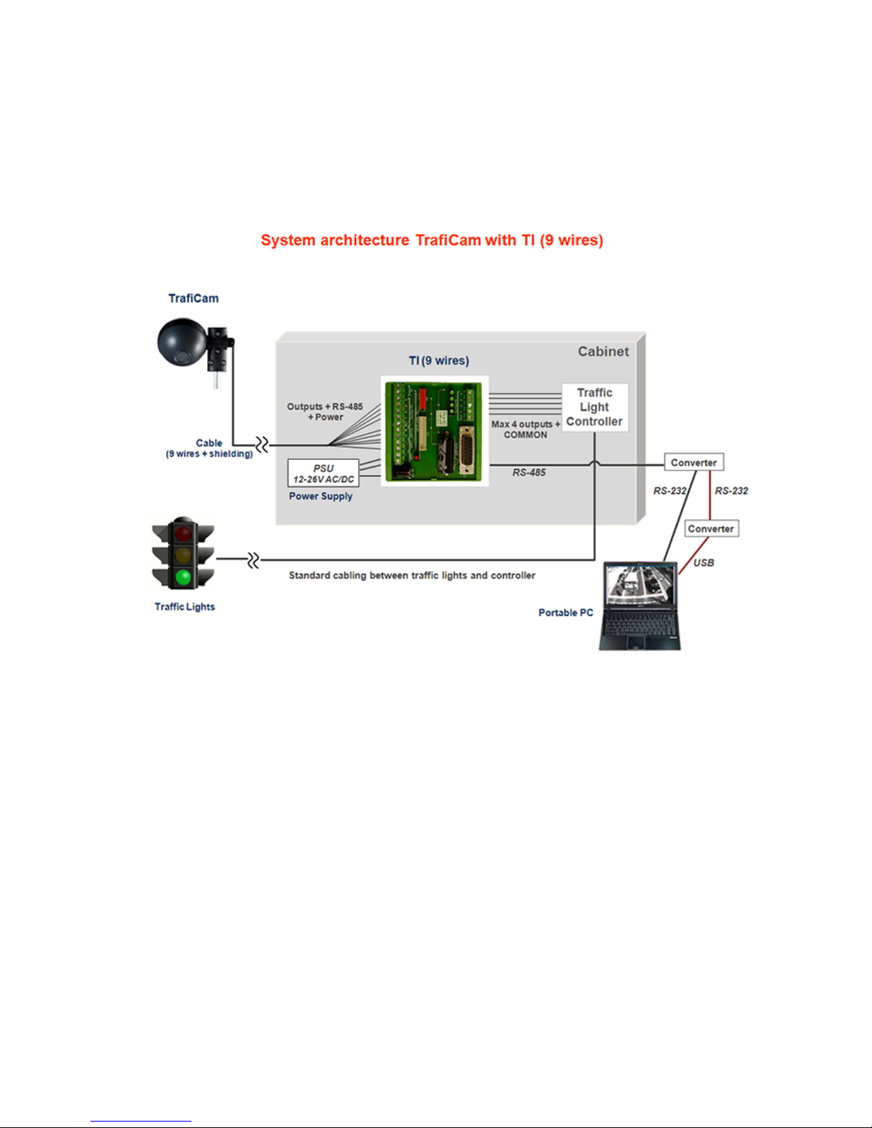
Architecture of the TrafiCam system
Page 8

4WX
TrafiCam with TI (9 wires)
The TrafiCam sensor
A
C
B
A = The lens
B = The gland to insert the connection cable
between sensor and interface
C = The sensor LED
D
E
D = The screws on the rear shell (to open the sensor)
E = The rotating point to fix the mounting bracket
Front and side view of the TrafiCam sensor
B
CN1
A
C
CN2
CN1, CN2 = The connectors to the TI (9 wires) interface
CN1, CN2 pinout: see next.
A = The fixation plate (to keep the connection cable in its
place)
B = The product label
C = Flatten ed side of the rear shell (as an aid to close the
sensor)
The TrafiCam sensor opened
Page 9

5WX
TrafiCam with TI (9 wires)
The tables below illustrate the pinout of the connectors CN1 and CN2 and the indicator code of the TrafiCam LED.
Pinout of connector CN1 Pinout of connector CN2
Pin Description Pin Description
+ + Power supply 1 Output 1
- - Power supply 2 Output 2
Grounding 3 Output 3
A RS-485A 4 Output 4
B RS-485B Ref Common output
LED Indication
On (off)
Flashing
Single flash
Double flash
Triple flash
Off (permanently)
Vehicle presence detection (no detection)
TrafiCam in boot mode
Failsafe mode - detection recall
Failsafe mode - quality recall
TrafiCam is learning
No power
Page 10
6WX
TrafiCam with TI (9 wires)
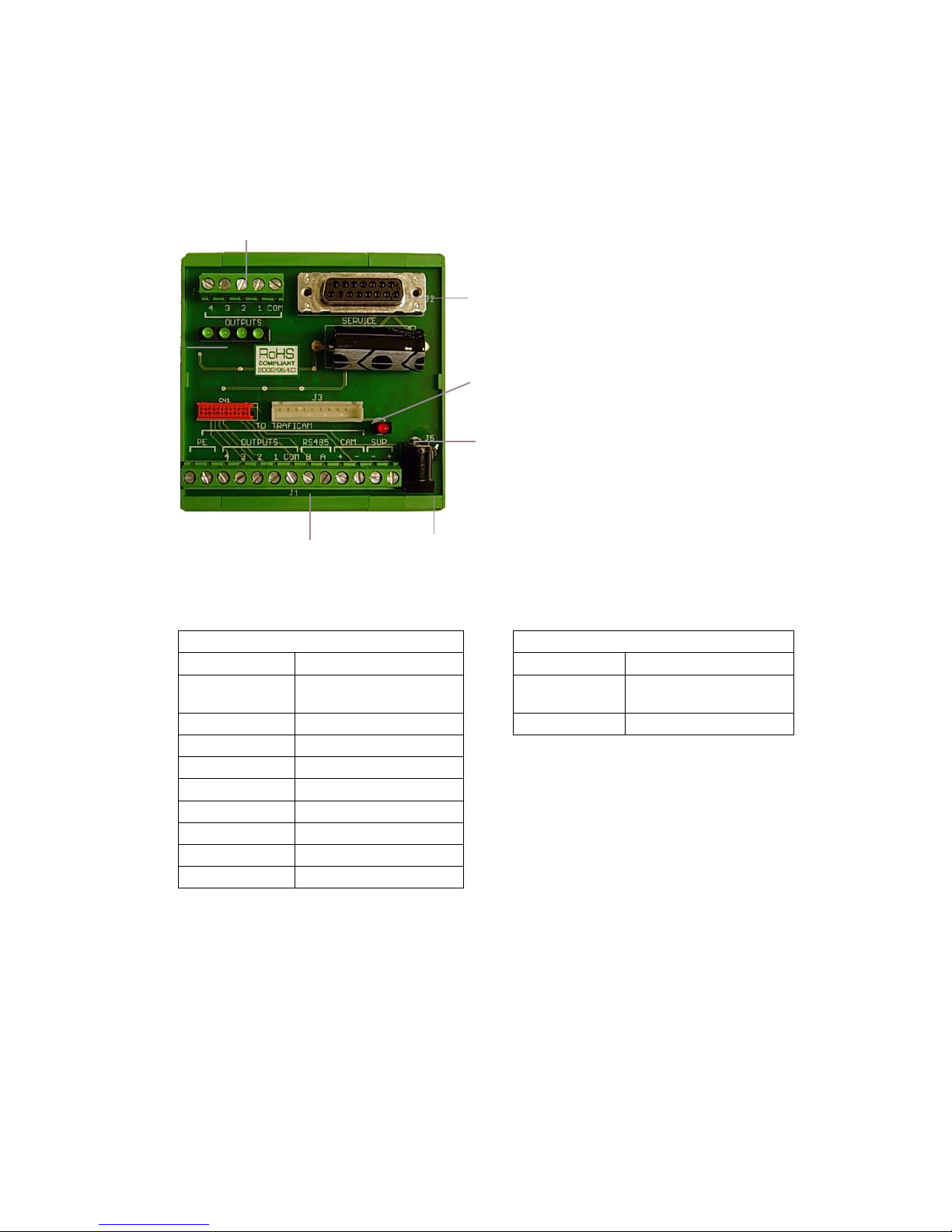
The interface
B
A
J5
J4
J2
J1
J3
A = The LEDs for outputs 1 to 4
B = The power LED
J1 = The connector to the TrafiCam sensor
J2 = The connector to the PC
J3 = The service connector
J4 = The connector to the traffic controller
J5 = The PSU connector
The tables below illustrate the pinout for
connectors J1 and J4.
The TI (9 wires) interface
Pinout of connector J1 Pinout of connector J4
Pin Description Pin Description
CAM - - Power supply Common Common ou t pu t
(for output 1 to 4)
CAM + + Power supply Output 1 - 4 Output 1 to 4
RS-485A RS-485A
RS-485B RS-485B
Outputs COM Common output ground
Outputs 1 Output 1
Outputs 2 Output 2
Outputs 3 Output 3
Outputs 4 Output 4
Page 11
7WX
TrafiCam with TI (9 wires)
The cables for connection
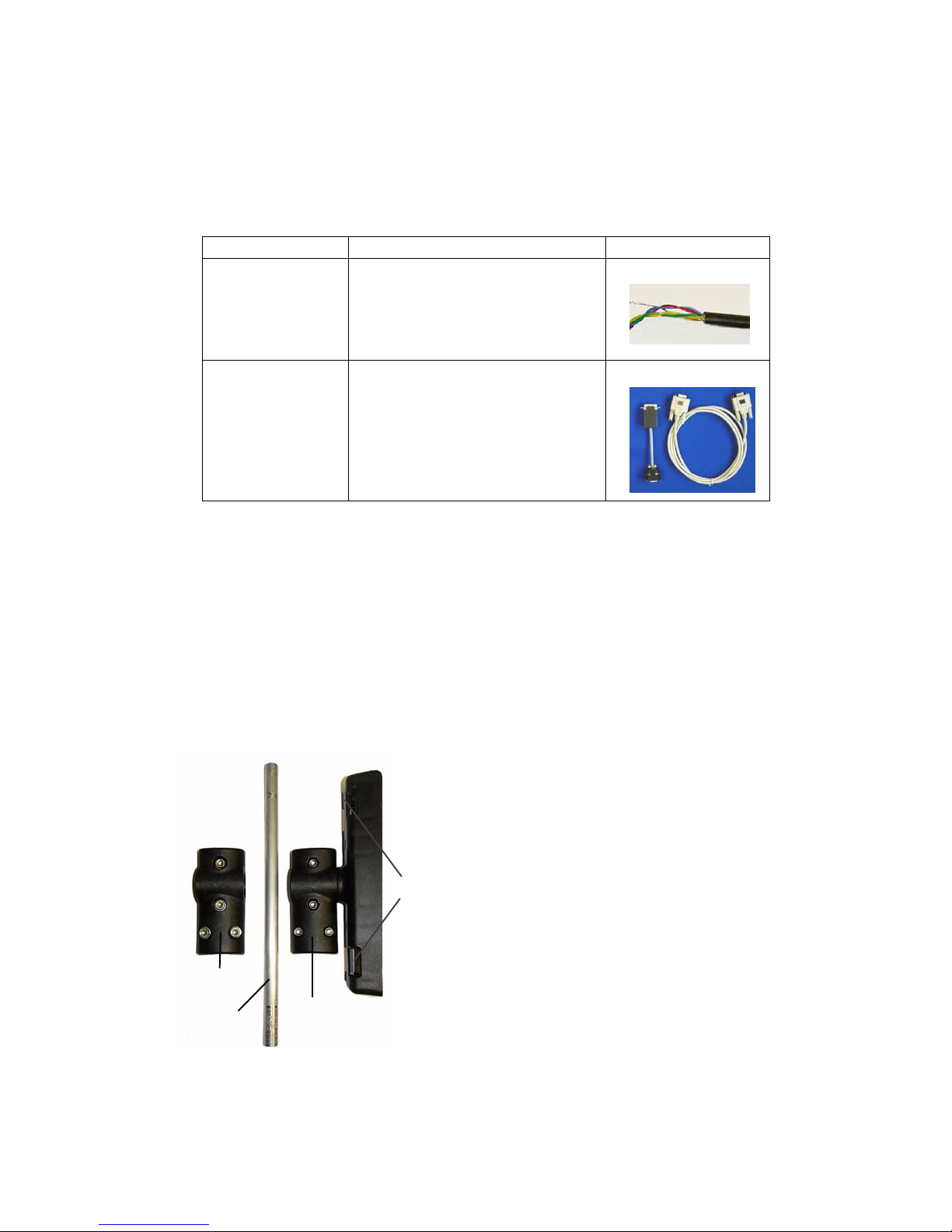
The table below gives an overview of the cables used for connecting the TrafiCam sensor, the interface and the PC.
Connection Cable Illustration
Sensor to interface UV -resistant, 9 wires + shielding
STP, cable d. 5-9,2 mm, min 5x2 + shield
min. wire d. 0,3 mm
Interface to PC RS-232 to RS-485 co nverter cable + DB9
serial cable
The cables for connection
The accessories for mounting
There is a mounting bracket for the TrafiCam sensor and a mounting bracket to the pole. The tube connects both
brackets.
C
A
B
D
A = The mounting bracket for the TrafiCam sensor
B = The tube
C = The mounting bracket to the pole
D = The holes to put the retaining straps through
The mounting accessories (brackets and tube)
Page 12
8WX
TrafiCam with TI (9 wires)
3. Installation
Do not remove the lens cover until TrafiCam is installed.
Ensure that the system power is off before starting the installation.
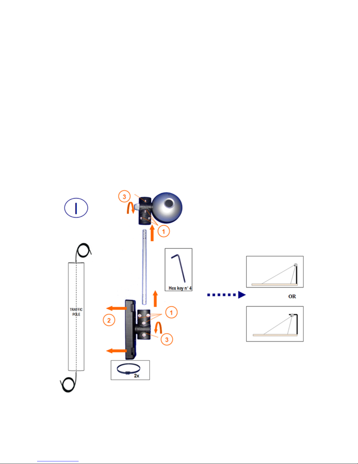
Step I: Mount the TrafiCam sensor on a stable pole.
• Fix the mounting tube to the brackets (Torque max = 1,3 Nm). (1)
• Fix TrafiCam to the pole using retaining straps. (2)
Put the retaining straps through the holes in the bracket.
• Position TrafiCam provisionally (Torque max = 1,3 Nm). (3)
You can mount TrafiCam in a horizontal or vertical position.
TrafiCam is a downward looking device.
Page 13
9WX
TrafiCam with TI (9 wires)
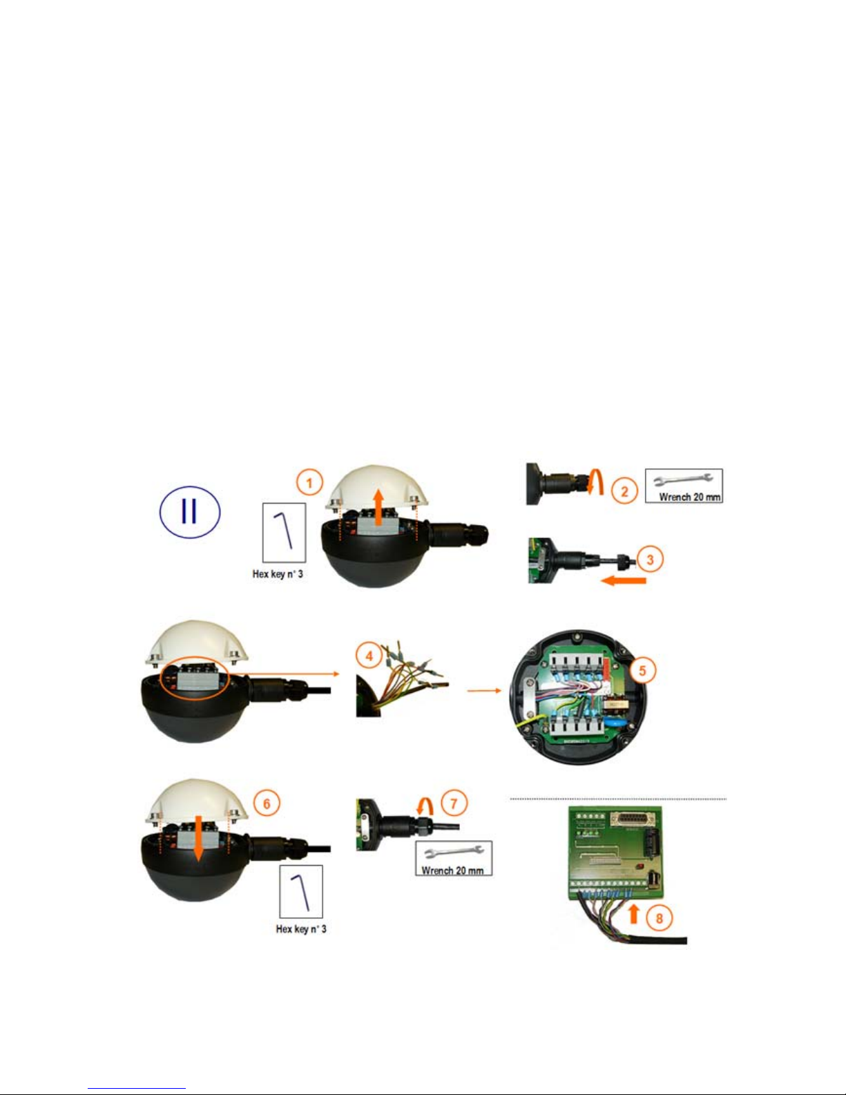
Step II: Connect the TrafiCam sensor to the interface.
Use a shielded twisted pair cable, UV-resistant, 10 wires+shield.
At the TrafiCam side:
• Open the sensor. (1)
• Loosen the cable gland. (2)
• Insert the cable into TrafiCam through the gland. (3)
• Strip the wires and fix the cable tags. Isolate the grounding wire. (4)
• Connect the cable to CN1 and CN2 and fix the cable plate. (5)
• Close TrafiCam (Torque max = 1,0 Nm). (6)
• Tighten the cable gland. (7)
At the interface side: (8)
• Connect the cable to the connector J1.
Page 14
10WX
TrafiCam with TI (9 wires)
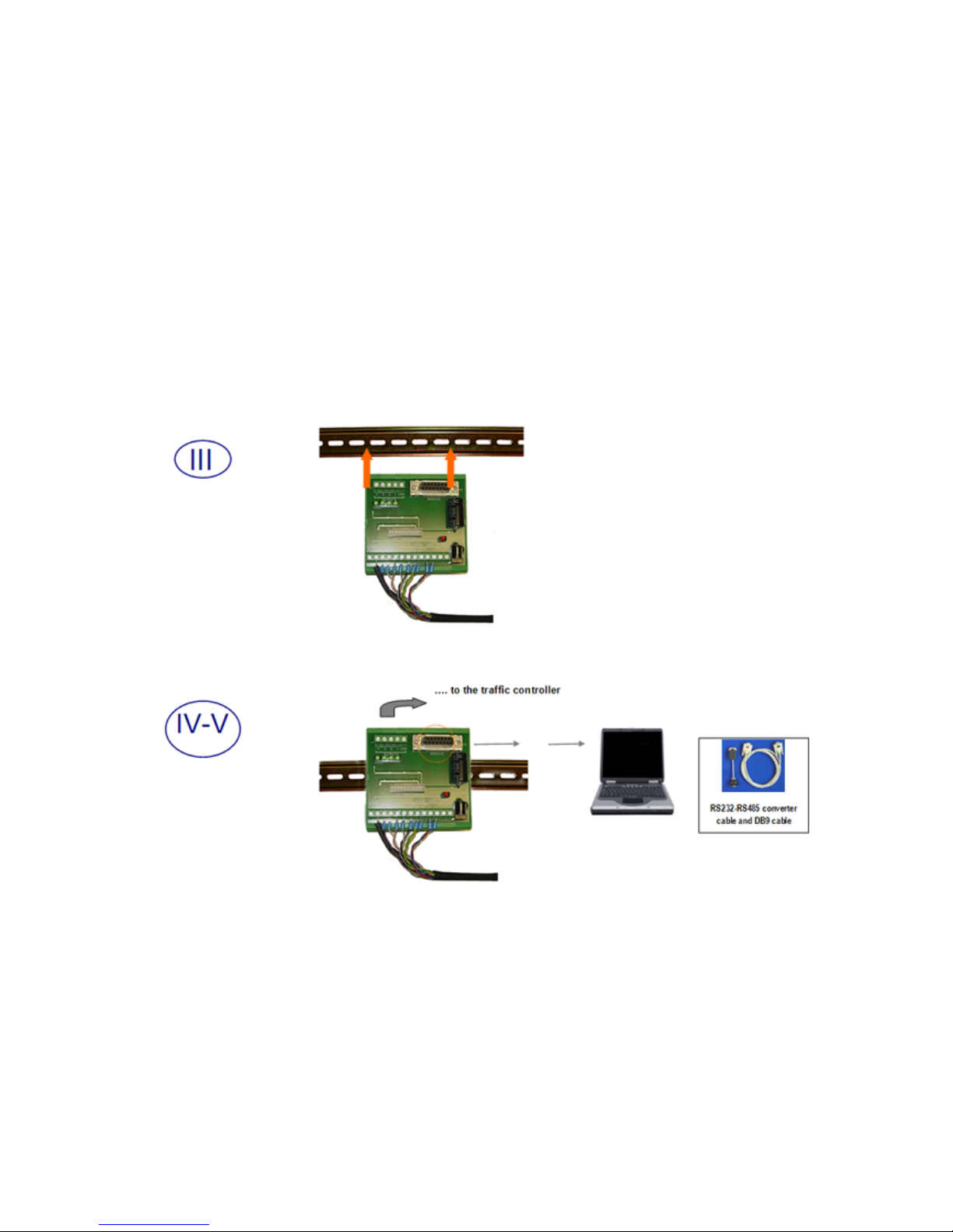
Step III: Mount the interface by clicking it on the DIN rail.
Step IV: Connect the interface to the traffic controller.
Step V: Connect the interface to the PC.
Use the RS-232 to RS-485 converter cable and the DB9 serial cable.
Finally connect the power supply and remove the TrafiCam lens cover.
You optimise the position of TrafiCam via visual verification (TrafiCam PC Tool, see next).
Always verify that there is no horizon in the image!
Tighten all screws after optimising the position of TrafiCam.
Page 15

11WX
TrafiCam with TI (9 wires)
4. Maintenance
The maintenance of TrafiCam can be done during the regular maintenance of the traffic lights and controller.
Instruction Frequency Tools Remark
Clean the faceplate of
TrafiCam.
Check the camera image.
Verify the configuration of the
system.
Once per year
Once per year
Soft cloth and mild
detergent
PC with TrafiCam PC Tool
Avoid movement of
TrafiCam.
Use the setup manual for
guidance.
Depending on the on-site conditions you may need to increase the frequency of maintenance.
Page 16

12WX
TrafiCam with TI (9 wires)
5. Software installation
TrafiCam is set up with TrafiCam PC Tool. This PC tool is available from the installation CD delivered with TrafiCam.
Install TrafiCam PC Tool
• Insert the TrafiCam installation CD in the CD-ROM drive.
• Go to the installation of TrafiCam PC Tool.
• Follow the instructions provided by the installation wizard.
• Click Finish to complete the installation.
Set the PC port for communication
• Start TrafiCam PC Tool.
• Select the appropriate COM port as the communication port.
To verify the COM port:
• Open the Control panel of the PC
• Select System, Hardware, Device Manager and then Ports.
The port is listed with its number.
• Click Retry.
Page 17
13WX
TrafiCam with TI (9 wires)
6. The work area of TrafiCam PC Tool
A
B
D
C
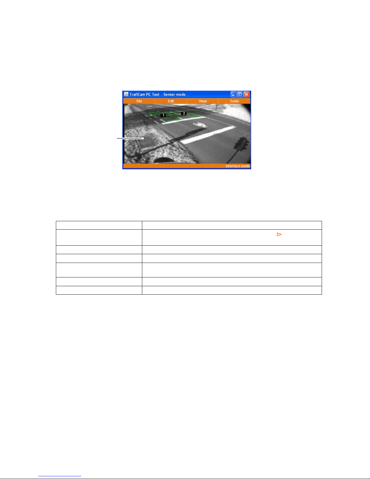
TrafiCam PC Tool - Sensor mode
A: Title bar B: Menu bar C: Status bar D: the TrafiCam sensor image
1, 2: the vehicle presence detection zones
How to Description
Open a menu or submenu
Click the menu item. A submenu is indicated via an arrow .
Close a menu by clicking outside the menu.
Activate a function Click the function.
Select a menu item Put the cursor on the menu item.
Set a parameter for a menu item Put the cursor on the menu item.
Use the arrow keys or the mouse scroll wheel to make the selection.
Refresh the sensor image Click Refresh Image from the View menu.
Set the language Select the language from the Tools menu.
Basic functions in TrafiCam PC Tool
Page 18
14WX
TrafiCam with TI (9 wires)
7. Set up the TrafiCam sensor
Edit the presence detection zones
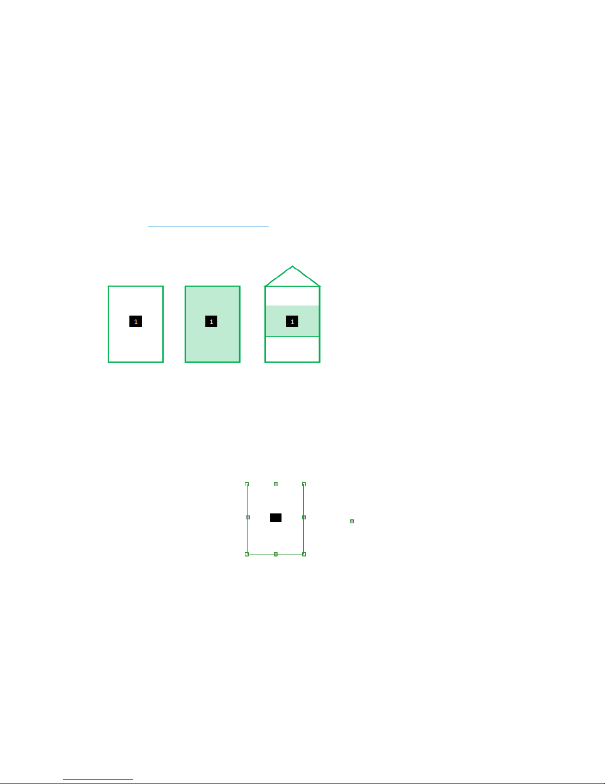
A zone can have 3 possible functions (detection modes):
• Presence: presence detection of moving and stationary vehicles (= default function)
• Stop: presence detection of stationary vehicles
• Loop: Vehicle counting
See Set the vehicle counting function.
A zone is displayed according to its detection mode.
Zone displayed according to its detection mode: presence (left), stop (middle) an d lo op (right)
The factory default setup of the TrafiCam sensor is displayed when you first open TrafiCam PC Tool. This default
configuration has one presence detection zone.
C
D
A
B
A, B, C, D: zone points
: direction point
1: output number
1
1
Presence detection zone with zone points and direction points
Note: To start a new setup from default factory settings: click New Configuration from the File menu.
If you wish to modify the setup of the TrafiCam sensor: click Get Configuration from the File menu.
Page 19

15WX
TrafiCam with TI (9 wires)
Edit the default presence detection zone
The Guidelines to edit the zones illustrate the advised size and position of a presence detection zone.
• Click-and-drag anywhere in the zone to move the zone.
• Put the cursor on a zone point.
• Click-and-drag the zone point to position it.
• Position the other zone points accordingly.
The zone should be made direction sensitive only in situations where veh icles i n the opposi te direction may cause
unwanted detection.
• Double-click the direction point to define the direction of the zone.
If you wish to delete the zone direction: double-click the direction point.
TrafiCam PC Tool assigns an output to the zone automatically. The number in the zone refers to the assigned
output. To change the assigned output: right-click the zone and select an output from the drop-down menu.
A zone is characterised by its Zone ID. To verify the zone I D : right-click the zone, the zone ID is displayed.
Add a zone
• Right-click anywhere on the sensor image except on a zone.
• Click the Add Zone pop-up.
• Edit the zone as described previously.
You can place up to 8 presence detection zones.
To delete a zone: right-click the zone and click the Delete Zone pop-up.
Set the zone to detect stationary vehicles only (stop detection mode)
• Choose Tools > Advanced Settin gs > Zone information.
• To set all zones: click All Zones and select Stop as the Detection Mode.
• To set one zone: select the zone and select Stop as the Detection Mode.
Set the output relation
You assign an OR or AND relation to the TrafiCam outputs:
• OR: the output changes status when presence is detected on at least one zone of the output.
• AND: the output changes status when presence is detected on all zones of the output.
• Select Outputs from the Edit menu.
• Select Output Relation.
• Use the arrow keys to set the output relation.
Default: Or
Selection: Or, And
Both the assigned and the unassigned outputs will close upon presence detection. If you wish to ch ange the output
mode, proceed as follows:
Change the output mode of the assigned outputs
• Select Outputs from the Edit menu.
• Select Output Mode.
• Use the arrow keys to set the mode.
Page 20

16WX
TrafiCam with TI (9 wires)
Default: Close on Event
Selection: Close or Open on Event
Change the output mode of the unassigned outputs
• Select Outputs from the Edit menu.
• Select Unassigned Outputs.
• Use the arrow keys to set the mode.
Default: Close
Selection: Close or Open
Activate the setup of TrafiCam
• Click Send Configuration from the File menu.
The configuration is sent to the TrafiCam sensor. This process is displayed in the status bar. After sending
TrafiCam PC Tool requests and displays the parameters of the activated setup.
TrafiCam starts a learning cycle. The learning cycle takes a few minutes. During the learning cycle all presence
detection zones are active and the outputs change their status accordingly.
When you View the detection a message will indicate that TrafiCam is learning. After the learning cycle the system
becomes operational.
Page 21
17WX
TrafiCam with TI (9 wires)
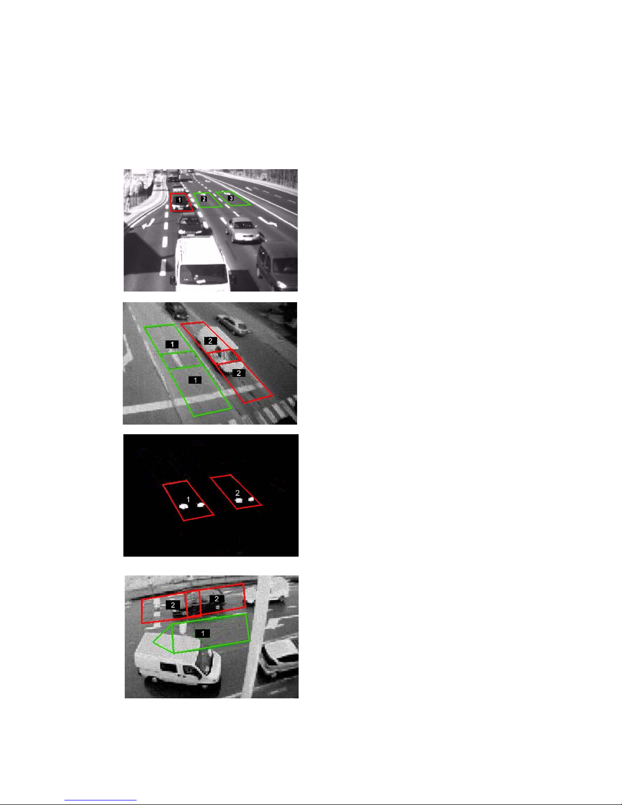
Guidelines to edit the zones
ALWAYS VERIFY THAT THERE IS NO HORIZON IN THE IMAGE!
SIZE AND POSITION OF THE ZONE
The zone should have the length and the width
of a regular vehicle.
For detection at the stop bar place the zone as
such that the vehicle will stop in the middle of
the zone.
Take into account that vehicles may stop well in
front of or over the stop line.
OVERLAPPING ZONES
To optimise detection, two overlapping zones
may be used. These zones are assigned to the
same output.
Overlapping zones minimize the chance that a
car stops in front or behind a zone.
DETECTION AT NIGHT
The detection zones should cover the
headlights in every situation.
At night the detection is on the headlights of the
vehicle.
DIRECTION SENSITIVITY
The zone should be made direction sensitive in
situations where vehicles in the opposite
direction may cause unwanted detection.
Page 22

18WX
TrafiCam with TI (9 wires)
8. Advanced settings
The advanced settings of the TrafiCam sensor are either not activated or a default value is assigned. Depending on
specific local situations modifications may be useful. Please contact your supplier before changing the advanced setup
parameters.
Advanced settings include the following functions:
• The failsafe function (detection and quality recall)
• The filtering functions (suppression of unwanted detection caused by wrong-way drivers, camera
movement, tree shadows or light reflection)
Note: Output pulse information, zone information and zone colours are described in Other functions.
Proceed as follows to change the advanced settings:
• Select Advanced Settings from the Tools menu.
• Select a parameter.
• Use the arrow keys to set the parameter.
Parameters, description and settings are described hereafter.
The failsafe function
TrafiCam has a failsafe function (or recall) related to detection and a failsafe function related to quality (detection recall
and quality recall). The recall status is indicated via a pop-up when you view the detection (see View the detection).
Detection Recall
All outputs assigned to recall will change status when there are no vehicles detected during a period defined by the
recall activation delay. The moment a vehicle is detected again on one of the zones, the recall status is deactivated.
Assign Recall Function
Default: Enabled
Selection: Disabled, enabled
Recall Activation Delay
Default: 60 min
Selection: --, 1 to 999 min
Quality Recall
All outputs assigned to recall will change status when the quality (image or detection quality) decreases below a set
threshold. With a lower threshold the camera is less sensitive for a decreasing image or detection quality. You also set
the delay time for (de)activation of the recall status. The image and detection quality parameters are displaye d when
you
View the detection.
Image Quality / Detection Quality Threshold
Default: 4
Selection: 0 to 10
Quality Time Out
Default: 4 min
Selection: 1 to 99 min
Page 23

19WX
TrafiCam with TI (9 wires)
The filtering functions
Inverse direction suppression
This function avoids that wrong- or sideway traffic causes unwanted detection. Inverse direction suppression applies to
direction sensitive zones only. You set the sensitivity of the suppression function and the delay time for the activation
of an inverse direction event.
Inverse Direction Suppression Time
Default: 10 s
Selection: 1-30 s
Inverse Direction Sensitivity
Default: Low
Selection: Low , High
Camera movement suppression
This function avoids unwanted detection in a situation where TrafiCam is moving (mounted on a p ole that may be
swinging because of the wind). You set the level of suppression. A high level may reduce the detection sensitivity.
Mode
Default: Off
Selection: On, Off, Day, Night
Level
Default: Low
Selection: Low, Medium, High
Tree shadow suppression
This function avoids unwanted detection caused by continuously moving shadows over the image.
Default: Disabled
Selection: Disabled, Enabled
Note: You should set one type of suppression only: camera movement or tree shadow suppression.
Do not activate both suppression functions simultaneously.
Reflection suppression
This function suppresses unwanted detection caused by the reflection of hea dlights. Reflection suppression applies
only to situations with overhead position of TrafiCam and advance presence detection on upcoming traffic. You set the
maximum duration of reflection suppression; after that period, detection will be activated.
Mode
Default: Off
Selection: On, Off
Presence Time On
Default: 60 s
Selection: 1-999 s
Other advanced settings
Presence Time Off
This parameter defines the maximum delay time for deactivation of the presence detection. By default it is set to 4
minutes since intersection cycle lengths rarely exceed this time.
The zone will relearn when presence is detected for a duration longer than the Presence Time Off parameter. You only
change this parameter when the cycle length of the intersection is not standard.
Page 24

20WX
TrafiCam with TI (9 wires)
Default: 240 s
Selection: 10-600 s
Detection LED
You can stop the indicator function of the detection LED.
Default: Enabled
Selection: Disabled, Enabled
Page 25
21WX
TrafiCam with TI (9 wires)
9. Other functions
View the detection
TrafiCam PC Tool allows to view live detection on the whole video image or on a single presence detection zone.
Traficon recommends to use this function only for diagnostic purposes; viewing live detection may reduce the
performance of the TrafiCam sensor.
View live detection on the whole video image
• Click View Detection from the View menu.
You view detection on the whole image.
View live detection on a single presence detection zone
• Click the detection zone.
• Click View Detection from the View menu.
You view detection on the presence detection zone. The rest of the video image does not change.
To stop viewing: click Refresh Image from the View menu.
Also the following information is displayed when you view live detection.
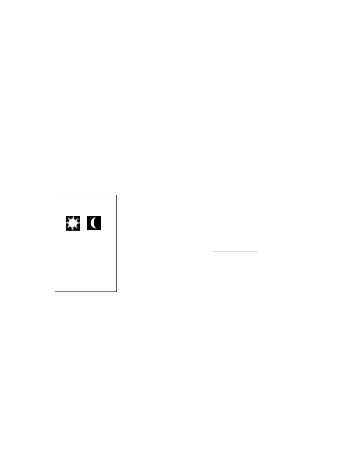
Display:
day night
Im Q: 10
Det Q: 10
Comm Q: 100%
Information:
Detection mode
Quality (image and detection quality, see The failsafe function)
Optimum quality = 10
Communication quality (between sensor and interface)
Set the delay and extend time for a zone
TrafiCam allows to define a delay time and an extend time for each presence detection zone.
The delay time is defined as the time between presence detection and the status change of the output. When a vehicle
enters the zone the output is delayed until the delay time expires.
The extend time is the time between the moment whe n the vehicle lea ves the zone an d the momen t when the ou tput
from that zone expires. If another vehicle enters the detection zone before the extend timer times out, the detection is
held and the extend timer is reset. When the extend timer times out the delay timer has to expire be fore another
presence detection can be received.
Via the extend mode, you can set the extension of presence dete ction during day or night only.
• Select Advanced Settings from the Tools menu.
• Select Zone Information.
Page 26

22WX
TrafiCam with TI (9 wires)
• Select All Zones... if you wish to set the extend and delay time for all zones.
To set the extend and delay time per zone: select a zone from the list.
• Use the arrow keys to set the Extend Mode, the Delay Time and Extend Time.
Default: on (Extend mode)
Selection: on, day, night
Default: 0 s (Delay and Extend Time)
Selection: 0-99,9 s
• Click OK.
Set the vehicle counting function
TrafiCam provides a vehicle counting function based on pulses which are sent to the contro ller. The number of pulses
corresponds with the number of vehicles, the length of the pulse indicates the zone occupancy.
Traficon advises to use the vehicle counting function only when the TrafiCam sensor is mounted in a rather vertical
position with presence detection in the area close to the camera (see also Appen dix 1: Lens selection and camera
positioning).
For vehicle counting, a detection zone configured in loop mode is required. This zone is similar to a presence detection
zone (see
Edit the default presence detection zone). You edit the zone as a presence detection zone and an output is
assigned. However a loop mode zone must have a direction.
A presence detection zone and a loop mode zone function independen tly. You can place a loop mode zone over a
presence detection zone.
The maximum number of zones (presence and loop mode) is limited to 8.
• Select Advanced Settings from the Tools menu.
• Select Zone Information and select a zone from the list.
To set all zones as loop mode zones: select All Zones... from the list.
• Set the detection mode to Loop.
This zone will now function as a vehicle counting zone.
Note: Verify that all zones configured in loop mode have a direction. You can not send the configuration to the sensor
if one or more loop mode zones do not have a direction.
Set the pulse generation function
This function applies to presence detection zones only.
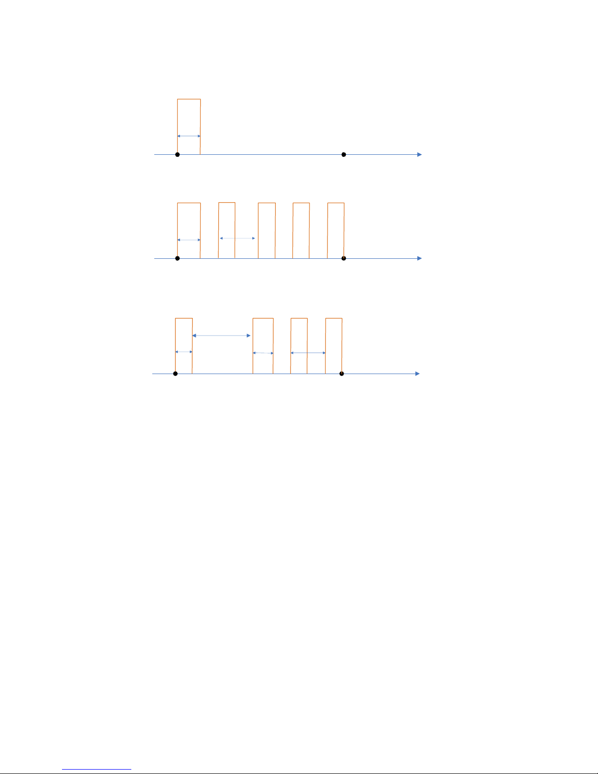
TrafiCam can send pulses to the controller during presence detection.
You define the pu lse mode, pulse time, the delay time and the pulse period. The generation of pulses a s a fu nction of
these parameters is illustrated hereafter.
Page 27
Start
presence detection
End
presence detection
time
Pulse
Pulse
time
Delay time = 0
Period = 0
End
presence detection
Pulse
Pulse period
PulsePulse
End
presence detection
Pulse
Delay time
Pulse period
PulsePulse
Start
presence detection
Start
presence detection
Delay time = 0
Pulse
time
Pulse
Pulse
time
½ Pulse period
time
time
Pulse
Pulse
23WX
TrafiCam with TI (9 wires)
Pulse generation function
• Select Advanced Settings from the Tools menu.
• Select Output Pulse Information.
• Select All Outputs... if you wish to set the pulse generation parameters for all zones.
To set the pulse generation parameters per zone: se lect an output from the list.
• Use the arrow keys to set the Pulse Mode, the Pulse Time, the Delay Time and the Pulse Period.
Default: none (Pulse mode)
Selection: none, entry, exit
Default: : 4,0 s (Pulse time)
Selection: 0,1-99,9 s
Default: 0 s (Delay time)
Selection: 0-99,9 s
Default: 0,0 (Pulse period)
Selection: 0,0-9,9 s
• Click OK.
Save or load the setup of a TrafiCam sensor
You can save the complete setup of the TrafiCam sensor as an XML file for backup purposes, for electronic exchange
or to copy the setup to another TrafiCam sensor.
Save a configuration to the PC
After you have set up the TrafiCam sensor:
Page 28

24WX
TrafiCam with TI (9 wires)
• Click Save As... from the File menu.
• Specify a file name and location.
• Click Save.
The configuration is saved as an XML file on to the PC.
Load a configuration to the TrafiCam sensor
• Click Open... from the File menu.
• Select the XML file.
• Click Open.
TrafiCam PC Tool displays the loaded configuration.
You modify the setup first or you activate this configuration for the TrafiCam sensor:
• Click Send Configuration from the File menu.
TrafiCam starts a learning cycle. The learning cycle takes a few minutes. During the learning cycle all zones are
active and the outputs change their status accordingly.
Upgrade firmware
• Click Upgrade Firmware from the Tools menu.
• Select the firmware file on the PC.
• Click Open.
The firmware upgrade process takes a few minutes. A pop-up window displays the status of the process.
• Click Close.
TrafiCam remains operational during the upgrade process.
To view product information, Select About... from the Tools menu. A pop-up window displays the product serial
number, the hardware revision, the firmware version and the lens type of the TrafiCam sensor.
Change the colour of the zones
The display colour of the zones in TrafiCam PC Tool is set by default. Proceed as fo llows if yo u wish to change these
colours:
• Select Advanced Settings from the Tools menu.
• Select Zone Colours...
• Click Set Colour to change the display colour of the zones.
• Click OK.
Page 29

25WX
TrafiCam with TI (9 wires)
10.Hardware specification TrafiCam
CAMERA
CMOS, black & white, sensor 1/3”, resolution 640x480, frame rate 30 FPS
LENS TYPE > Wide angle Narrow angle
DIMENSIONS
L x H x W: 45 cm x 16 cm x 10 cm mounted vertically
41 cm x 18 cm x 10 cm mounted horizontally
Mass (including mounting bracket, excluding cable): 600 g
Sensor diameter: 10 cm
MATERIALS
Sensor
Front and back shell: polycarbonate
Mid section: fibre reinforced polyamide
Mounting bracket: fibre reinforced polyamide
Tube: aluminium
COMMUNICATION
RS485 service port for configuration
OUTPUTS
4 optical coupled dry contacts; Imax = 50 mA, Pmax = 300 mW, Umax = 48 VDC
POWER SUPPLY VOLTAGE INPUT
12-26 V AC/DC
POWER CONSUMPTION
85 mA @ 12 V DC (1,2 W)
50 mA @ 24 V DC (1,2 W)
ENVIRONMENTAL
Temperature range: between - 34°C and +80°C
0 to 95% relative humidity, non-condensing
Housing: waterproof to IP67
Materials: weatherproof, UV-resistant
REGULATORY
EMC: Electromagnetic Compatibility - 204/108/EG
FCC: FCC part 15 Class A
NEMA: NEMA II Shock and vibration
Focal distance 3,0 mm 8,0 mm
Field of view - horizontal 95° 32°
Field of view - vertical 65° 22°
Field of view - diagonal 103° 39°
Page 30

26WX
TrafiCam with TI (9 wires)
11.Hardware specification TI (9 wires)
DIMENSIONS
L x H x W: 8 cm x 8 cm x 4 cm; DIN-rail clickable
Mass: 100 g
COMMUNICATION
RS-485 between TI (9 wires), PC and TrafiCam
OUTPUTS
4 optical coupled dry contacts (detection output)
(Pmax = 300 mW, Imax = 50 mA, Umax = 48 V DC)
POWER SUPPLY VOLTAGE INPUT
12-26 V AC/DC
POWER CONSUMPTION
120 mA @ 12 V DC (1,5 W)
60 mA @ 24 V DC (1,5 W)
REGULATORY
No active components
Page 31
27WX
TrafiCam with TI (9 wires)
12.Appendix
Appendix 1: Lens selection and camera positioning
2 types of TrafiCam sensors are available:
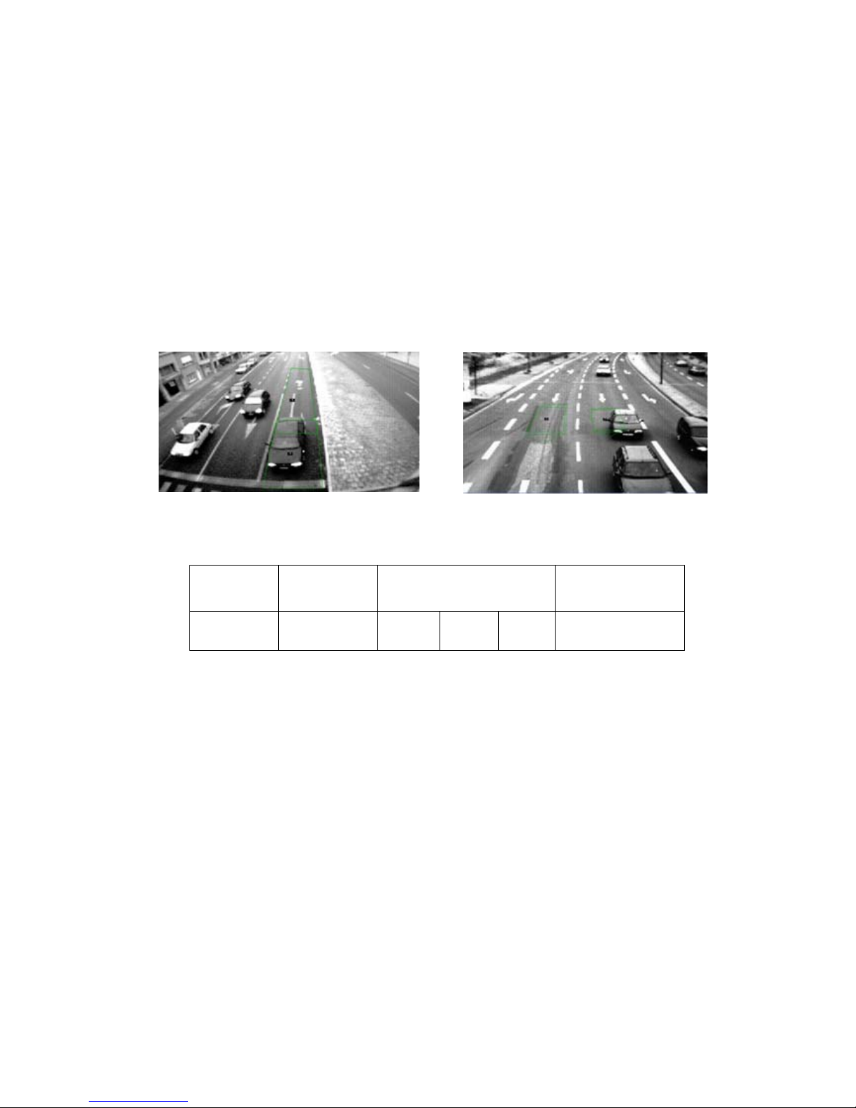
• Wide angle lens
Vehicle presence detection in the area close to the camera: detection of vehicles at the stop bar
• Narrow angle lens
Vehicle presence detection in the area more distant from the camera: advance detection of vehicles
approaching the intersection
Wide angle lens
Narrow angle lens
Version Focal dist an ce
Angle of view
Vertical Horizontal Corner to
corner
Detection area
Wide angle 3,0 mm 65° 95° 103° 0 to 25 m (0 - 80 ft)
Narrow angle 8,0 mm 22° 32° 39° 15 to 75 m (45 - 250 ft)
TrafiCam lens specifications
Guidelines for the sensor position
• Height: mount TrafiCam as high as possible.
• Position towards the road: position TrafiCam overhead if possible. If not, a side-fired position next to the fastest
lane is recommended.
• Orientation: do not point TrafiCam at the horizon. Place the camera in a position that will have minimum exposure
to direct sunlight.
The height and position of TrafiCam are important factors for minimizing occlusion. Occlusion occurs when a vehicle
blocks out part of the field of view of TrafiCam. Please contact your supplier if you wish more information on how to
reduce or avoid occlusion.
Page 32
28WX
TrafiCam with TI (9 wires)
The detection area in relation to the camera height and the minimum detection distance
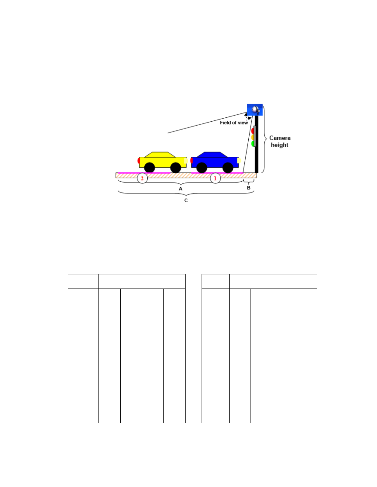
The image below illustrates the detection area, minimum and maximum detection distance. Presence detection zones
should be positioned within the detection area.
Detection area (A), minimum detection distance (B), maximum detection distance (C)
and presence detection zones (1, 2)
Detection area, minimum and maximum detection distance are related to the camera height and the lens type.
TrafiCam wide angle lens
Camera
height
Maximum detection distance Camera
height
Maximum detection distance
Min.
detection
distance
0 m 1 m 2 m 3 m
Min.
detection
distance
0 ft 3 ft 7 ft 10 ft
3 m 6 m 25 m 25 m 25 m 9 ft 20 ft 80 ft 80 ft 80 ft
4 m 8 m 20 m 25 m 25 m 13 ft 26 ft 66 ft 80 ft 80 ft
5 m 10 m 20 m 25 m 25 m 16 ft 33 ft 66 ft 80 ft 80 ft
6 m 12 m 21 m 25 m 25 m 20 ft 39 ft 69 ft 80 ft 80 ft
7 m 15 m 23 m 25 m 25 m 23 ft 49 ft 75 ft 80 ft 80 ft
8 m 17 m 24 m 25 m 25 m 26 ft 56 ft 79 ft 80 ft 80 ft
9 m 19 m 25 m 25 m 25 m 30 ft 62 ft 80 ft 80 ft 80 ft
10 m 21 m 25 m 25 m 25 m 33 ft 69 ft 80 ft 80 ft 80 ft
11 m 23 m 25 m 25 m 25 m 36 ft 75 ft 80 ft 80 ft 80 ft
12 m 25 m 25 m 25 m 25 m 39 ft 80 ft 80 ft 80 ft 80 ft
13 m 25 m 25 m 25 m 25 m 43 ft 80 ft 80 ft 80 ft 80 ft
14 m 25 m 25 m 25 m 25 m 46 ft 80 ft 80 ft 80 ft 80 ft
15 m 25 m 25 m 25 m 25 m 49 ft 80 ft 80 ft 80 ft 80 ft
Maximum detection distance for TrafiCam with a wide angle lens - metric (left) and imperial (right)
Page 33

29WX
TrafiCam with TI (9 wires)
TrafiCam narrow angle lens
Camera
height
Maximum detection distance
6 m 7 m 8 m 10 m 12 m 15 m 18 m 20 m 25 m
3 m 37 m 75 m 75 m 75 m 75 m 75 m 75 m 75 m 75 m
4 m 19 m 29 m 50 m 75 m 75 m 75 m 75 m 75 m 75 m
5 m 15 m 20 m 28 m 62 m 75 m 75 m 75 m 75 m 75 m
6 m - 17 m 22 m 38 m 75 m 75 m 75 m 75 m 75 m
7 m - 16 m 20 m 30 m 48 m 75 m 75 m 75 m 75 m
8 m - - - 26 m 38 m 75 m 75 m 75 m 75 m
9 m - - - 24 m 33 m 57 m 75 m 75 m 75 m
10 m - - - 23 m 31 m 48 m 75 m 75 m 75 m
11 m - - - - 29 m 43 m 66 m 75 m 75 m
12 m - - - - 28 m 40 m 57 m 75 m 75 m
13 m - - - - 27 m 37 m 52 m 66 m 75 m
14 m - - - - - 36 m 49 m 60 m 75 m
15 m - - - - - 35 m 46 m 56 m 75 m
Camera
height
Maximum detection distance
20 ft 23 ft 26 ft 33 ft 39 ft 49 ft 59 ft 66 ft 82 ft
9 ft 121 ft 250 ft 250 ft 250 ft 250 ft 250 ft 250 ft 250 ft 250 ft
13 ft 62 ft 95 ft 164 ft 250 ft 250 ft 250 ft 250 ft 250 ft 250 ft
16 ft 49 ft 65 ft 91 ft 203 ft 250 ft 250 ft 250 ft 250 ft 250 ft
20 ft - 55 ft 72 ft 124 ft 250 ft 250 ft 250 ft 250 ft 250 ft
23 ft - 52 ft 65 ft 98 ft 157 ft 250 ft 250 ft 250 ft 250 ft
26 ft - - - 85 ft 124 ft 250 ft 250 ft 250 ft 250 ft
30 ft - - - 78 ft 108 ft 186 ft 250 ft 250 ft 250 ft
33 ft - - - 75 ft 101 ft 157 ft 250 ft 250 ft 250 ft
36 ft - - - - 95 ft 141 ft 216 ft 250 ft 250 ft
39 ft - - - - 91 ft 131 ft 186 ft 250 ft 250 ft
43 ft - - - - 88 ft 121 ft 170 ft 216 ft 250 ft
46 ft - - - - - 118 ft 160 ft 196 ft 250 ft
49 ft - - - - - 114 ft 150 ft 183 ft 250 ft
Maximum detection distance for TrafiCam with a narrow angle lens - metric (top) and imperial (bottom) units
Page 34
30WX
TrafiCam with TI (9 wires)
Appendix 2: Output wiring diagram
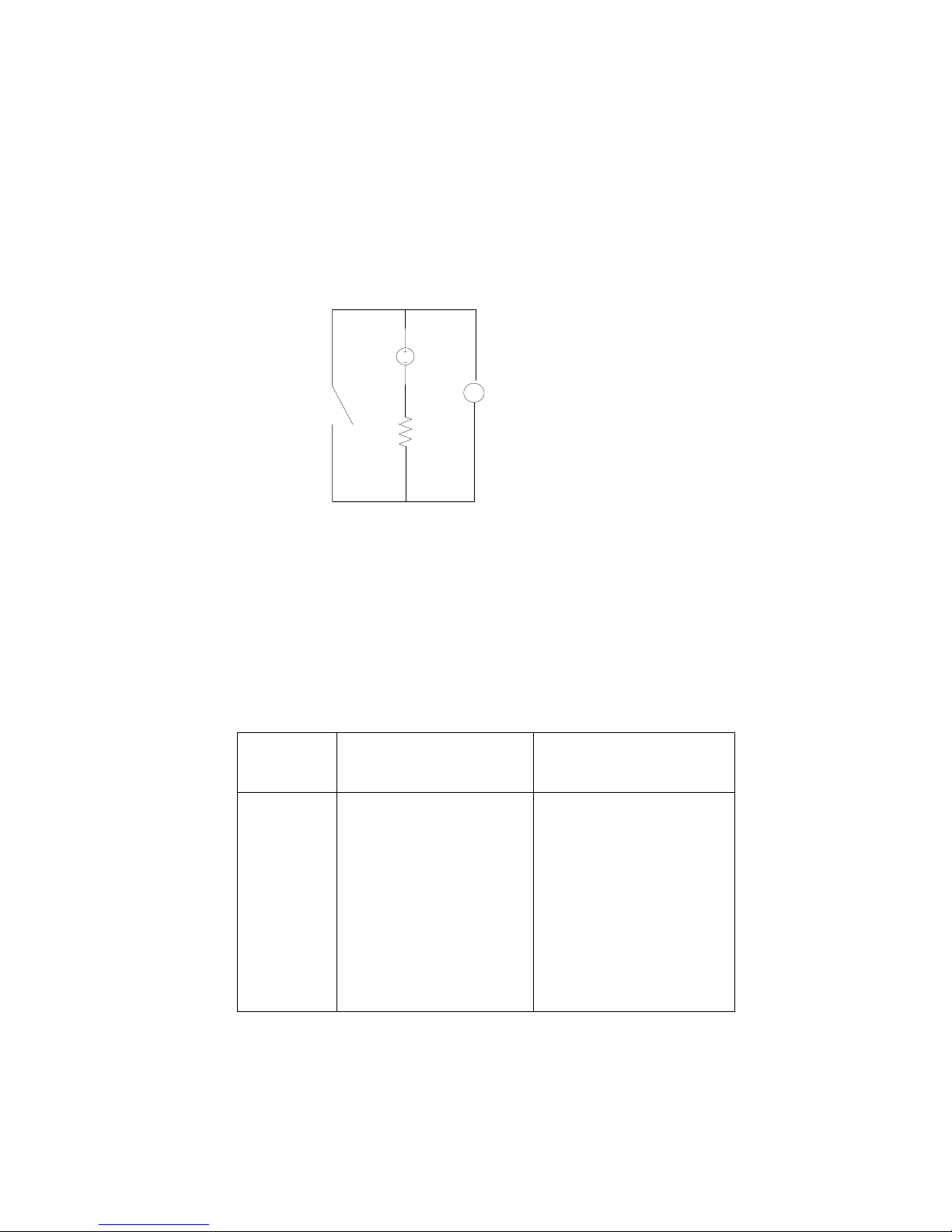
The TrafiCam device has 4 optical coupled dry contacts which serve as outputs. Via TrafiCam PC Tool you can set the
outputs to open or close upon presence detection.
The scheme below illustrates the wiring diagram for the outputs.
5 VDC
COMMON
TrafiCam OUTPUT ANALOG
INPUT
MEASURING
VOLTAGE
R= 10 kO
V
Open: U = 5 V
Closed: U = 0 V
Ir = 0, 5 mA
Pr = 2,5 mW
TrafiCam output wiring diagram
Appendix 3: Colour code of the cable wires
The cables for connection between the TrafiCam device and the interface are not included but can be supplied by
Traficon. Hereafter you find the wire colour code of the cables which Traficon supplies.
Cable
Wire Colour
use with 4TI/1 TI
(STP, UV-resistant, 4 wires +
shielding)
use with TI (9 wires)
(STP, UV-resistant, 10 wires +
shielding)
BLUE V-: GROUND V-: GROUND
RED V+: 10-24 VAC/DC V+: 10-24 VAC/DC
GREEN RS-485A RS-485A
YELLOW RS-485B RS-485B
BLACK - COMMON OUTPUT GROUND
GREY - OUTPUT 1
PINK - OUTPUT 2
WHITE - OUTPUT 3
PURPLE - OUTPUT 4
BROWN - -
Colour code of the cable wires
Page 35

31WX
TrafiCam with TI (9 wires)
Index
A
Advanced settings TrafiCam 18
C
Cable specifications 7
Connector pinout
TI (9 wires) connector J1 6
TrafiCam connector CN1
5
F
Failsafe function 18
Filtering unwanted detect io n 19
Firmware upgrade
24
H
Hardware specification
TI (9 wires) 26
TrafiCam
25
I
Installation
cable wire colour code 30
cables for connection
7
camera position guidelines 27
detection area and distance, camera height 28
mounting brackets and tube
7
output wiring diagram 30
stepwise process and illustration 8
Installation, software
12
Interface connectors 6
Interface hardware
6
L
Live viewing 21
M
Maintenance 11
O
Outputs
assigning TrafiCam outputs 15
setting the output relation 15
TrafiCam, changing the output mode
15
P
PC port for communication 12
Presence zones
adding or deleting a zone
15
assigning an output 15
defining the zone direction 15
delay and extend time
21
detection mode 14
editing the default presence zone 15
guidelines to edit the zones
17
stop detection mode 15
zone ID
15
R
Recall 18
detection recall 18
quality recall
18
T
TrafiCam LED deactivation 20
TrafiCam LED indicator code 5
TrafiCam PC Tool
basic functions
13
installation 12
work area basics
13
TrafiCam sensor
connectors 4
hardware
4
TrafiCam sensor selection 27
TrafiCam setup
activation
16
default factory setup 14
guidelines to edit the zones 17
learning cycle
16
loading a configuration 24
saving to a PC 23
V
Vehicle counting 22
Viewing detection 21
Viewing detection information display 21
Viewing product information
24
 Loading...