

TrafFix Devices 45032-W User Manual
TrafFix
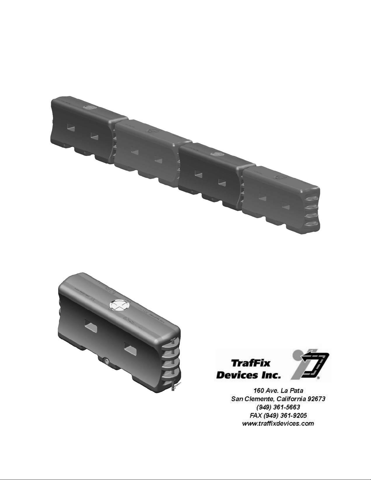
Water-Wall
®
™
Manual
TL-3 Barricade
TL-1 Longitudinal Barrier
PN 45035 Revision A (Dated 05/01/13)

Table of Contents
Page
Product Overview/Function ............................................................................................................. 1
Product Components and General Specifications ............................................................................ 2
Installation ....................................................................................................................................... 3
Recommendation for Stacking ....................................................................................................... 4
Deflection Clear Zone ...................................................................................................................... 5
Maintenance and Repair ................................................................................................................. 5
Water Freezing Prevention .............................................................................................................. 7
Redeployment To Another Site ....................................................................................................... 8
Limitations and Warnings ................................................................................................................ 9
Float Lid ........................................................................................................................................ 10
Appendix A: T
Appendix B: Drawings ............................................................................................................. 14-21
Appendix C: FHWA Product Acceptance Letter ......................................................................... 22
Appendix D: Regional Sales Managers, Key Contacts & Customer Service ........................... 23-24
rafFix Water-Wall Specifications ....................................................................... 11
160 Ave. La Pata
San Clemente, California 92673
(949) 361-5663
FAX (949) 361-9205
www.traffixdevices.com

Product Overview/Function
General description- The TrafFix Water-Wall™ is a plastic, water filled portable module that can
produce the desired energy attenuation characteristics to decelerate an impacting vehicle to meet
TL-1 for Longitudinal Barrier, TL-2 for Longitudinal Channelizing Device or TL-3 for Barricade
crashworthy requirements of Report NCHRP 350.
Advantages the T rafFix Water-Wall:
The TrafFix Water-Wall utilizes water dispersion upon impact that ruptures the plastic container and
disperses the contained water to prevent vehicle intrusion into the work zone.
-Features
Durable polyethylene plastic minimizes cracking and breaking
Molded through forklift holes eliminate bowing when filled with water
Double wall knuckle design minimizes breakage at hinge points
Hinge design allows for a 30-degree pivot between sections
Large 8" fill hole speeds filling process, includes twist-lock plastic cap
Tamper resistant, corner offset drain plug with coarse buttress thread - screws in or out in only 2 1/2
turns
Includes one steel connection pin that allows sections to be locked together
Forklift and pallet jack through holes and recesses for easy movement
Standard colors are orange or white — additional colors available upon request
Can use Optional "Drive By" Float Fill Cap for easy water level inspection from moving vehicle
Will accept the TrafFix Water-Wall Fence Panel, 45032-WWF, sold separately
-Linked units meet NCHRP-350 crashworthy test requirements for a TL-1 LONGITUDINAL
BARRIER
-Single units meet NCHRP-350 crashworthy test requirements for a TL-3 BARRICADE.
The TrafFix Water-Wall has been tested and passed all crash tests required by NCHRP Report 350
and meets all crashworthy acceptance criteria for use on the National Highway System. (Reference
FHWA Product Acceptance HSA-10/B130 and HSA-10/WZ-224)
Product Function
TrafFix Water-Wall sections are designed to link together to form a portable TL-1 longitudinal water
filled barrier that provides positive separation between moving vehicles and workers or pedestrians in
the protected zone.
Single TrafFix Water-Wall sections are designed to be used as a portable barricade in TL-1, TL-2, or
TL-3 applications.
Revision A (Dated 05/01/13) 1
Product Components and General Specifications
The TrafFix Water-Wall sections are Orange or White in color and have an outer shell
made from virgin low density polyethylene (LDPE) and have a water capacity of 122 gallons
[462 liters]. The polyethylene material is durable and recyclable and will break up in large
sections upon impact. It will not crack or corrode when left on the job site or stored for long
periods of time.
Overall Dimensions
Width: 18” [ 457 mm]
Height: 32” [ 812 mm]
Length: 73” [ 1854 mm] pin to pin
Weight:
Empty Weight: 79 lbs. [36 kg]
Filled Weight: 1,110 lbs. [503 kg]
Fill Capacity
Volume: 123 Gal [ 466 L]
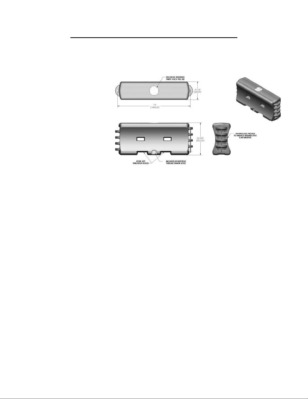
Each TrafFix Water-Wall section
contains an eight inch diameter
Figure 1: Sentry Water-Cable Barrier
water fill-hole located on the top
surface of each wall section. This large diameter opening allows easy access for water filling using a
water tanker truck or large diameter hose. Each TrafFix Water-Wall section comes with a twist lock
lid to cover the fill hole opening when the water filling process is complete. An optional water level
indicator built into the twist lock lid is available to show the section is properly filled (refer to pg. 10).
For draining, each TrafFix Water-Wall section has a centrally located drain hole designed at the bottom
of each wall section. Each drain hole contains molded-in Buttress threads. The drain plug requires
1-1/2 turns to seal the plug preventing any water leaks. The molded-in Buttress threads eliminate the
possibility of cross threading compared to standard threads used in a spin welded insert. Cracked spin
welded inserts may require repair and are typically not reliable, leading to water leaks. The TrafFix
Water-Wall, with its molded in Buttress threads, eliminates both issues of cross threading and insert
repair.
There are two forklift pockets located at grade level for lifting. Only these through holes should be
used to lift the TrafFix Water-Wall as identified in Figure 1 (or pg. 15).
Revision A (Dated 05/01/13) 2
Installation
Foundation Requirements
The TrafFix Water-Wall is free standing and only requires that the foundation support the weight of
the fully loaded sections. The foundations include concrete, asphalt, dirt and gravel.
Installation Instructions
The TrafFix Water-Wall will be delivered in two pieces. The first piece will be the water wall
barrier section with the twist lock fill cap and the buttress threaded drain plug installed. The
second piece will be the galvanized steel T-pin with the keeper pin installed.
Proper site planning will have identified the required quantity and placement of the TrafFix WaterWall. The sections should be removed from the transport vehicle using safe lifting and movement
procedures and emplaced as planned.
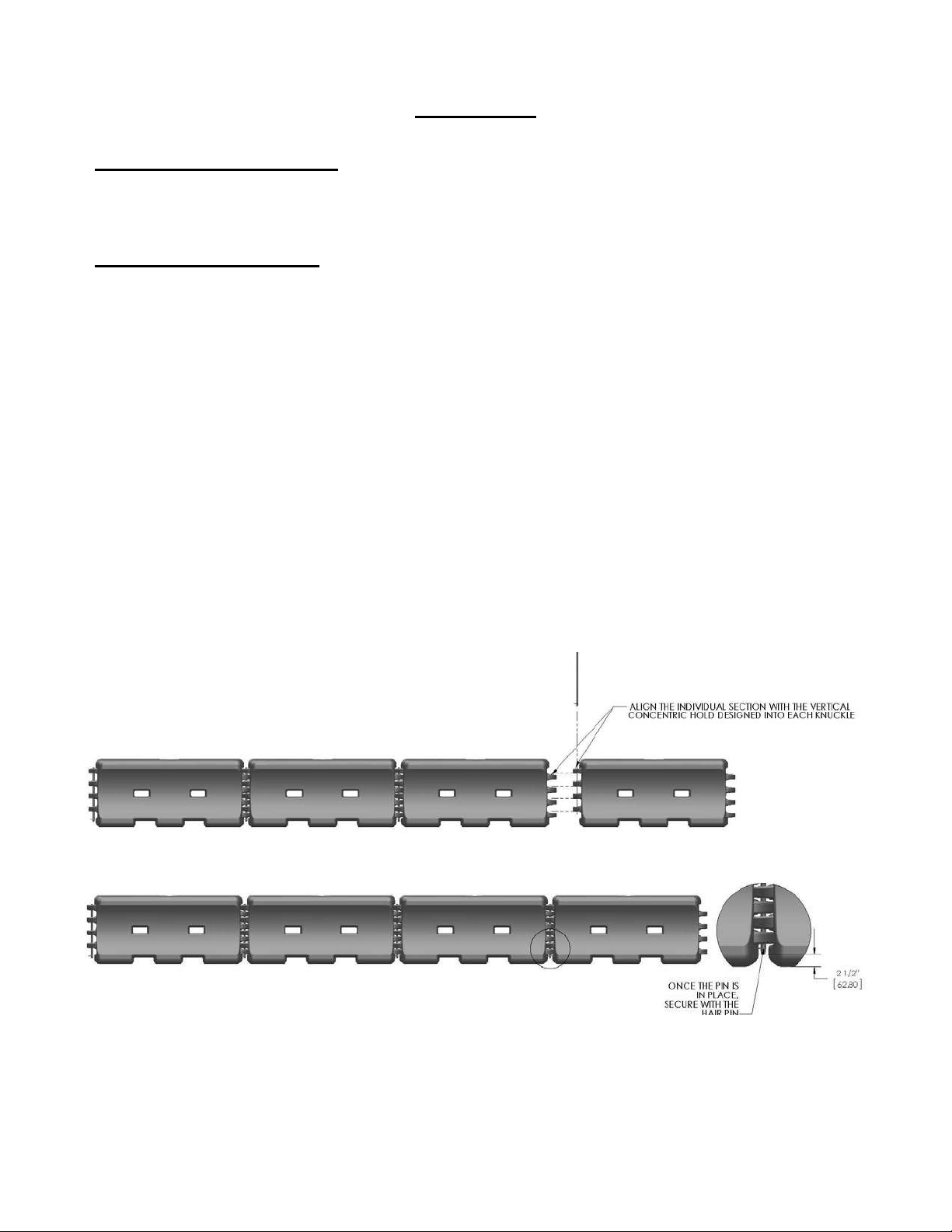
At the end of each TrafFix Water-Wall are vertical interlocking knuckles. Within the knuckles are a
series of vertical concentric holes as seen in Figure 2 (or pg. 16). When linking individual TrafFix
Water-Walls together, the knuckle holes are vertically aligned with the adjacent TrafFix Water-Wall.
This creates a series of eight vertical knuckles interlinked together with a vertical connecting T-pin
which is dropped through the concentric aligned holes. Located at the bottom of each T-pin is a
safety keeper pin which is inserted into the alignment hole at the bottom of each T-pin as seen in
Figure 2. The keeper pin must be inserted to finalize the installation on each wall section. The lower
end of the T-pin is approximately 2-1/2” above the grade surface as seen in Figure 2 to insure
that the pin is fully inserted.
Figure 2: Installation Assembly Guide Diagram
Revision A (Dated 05/01/13) 3
When the TrafFix Water-Wall has been placed in accordance with the site plan and the sections
fastened together, the twist lock fill cap for each section should be removed and the section filled with
water. The fill cap is then replaced insuring that all tabs are engaged. If the optional water level indicator is installed, insure that the level indicator becomes fully raised. Since the water level indicator is
built into the fill cap, care should be taken to insure that the water level indicator is not damaged during
the removal and re-installation process.
When all sections have been linked together, the T-pin and keeper pins installed, and the sections filled
with water including installation of the fill cap, the TrafFix Water-Wall is ready for use.
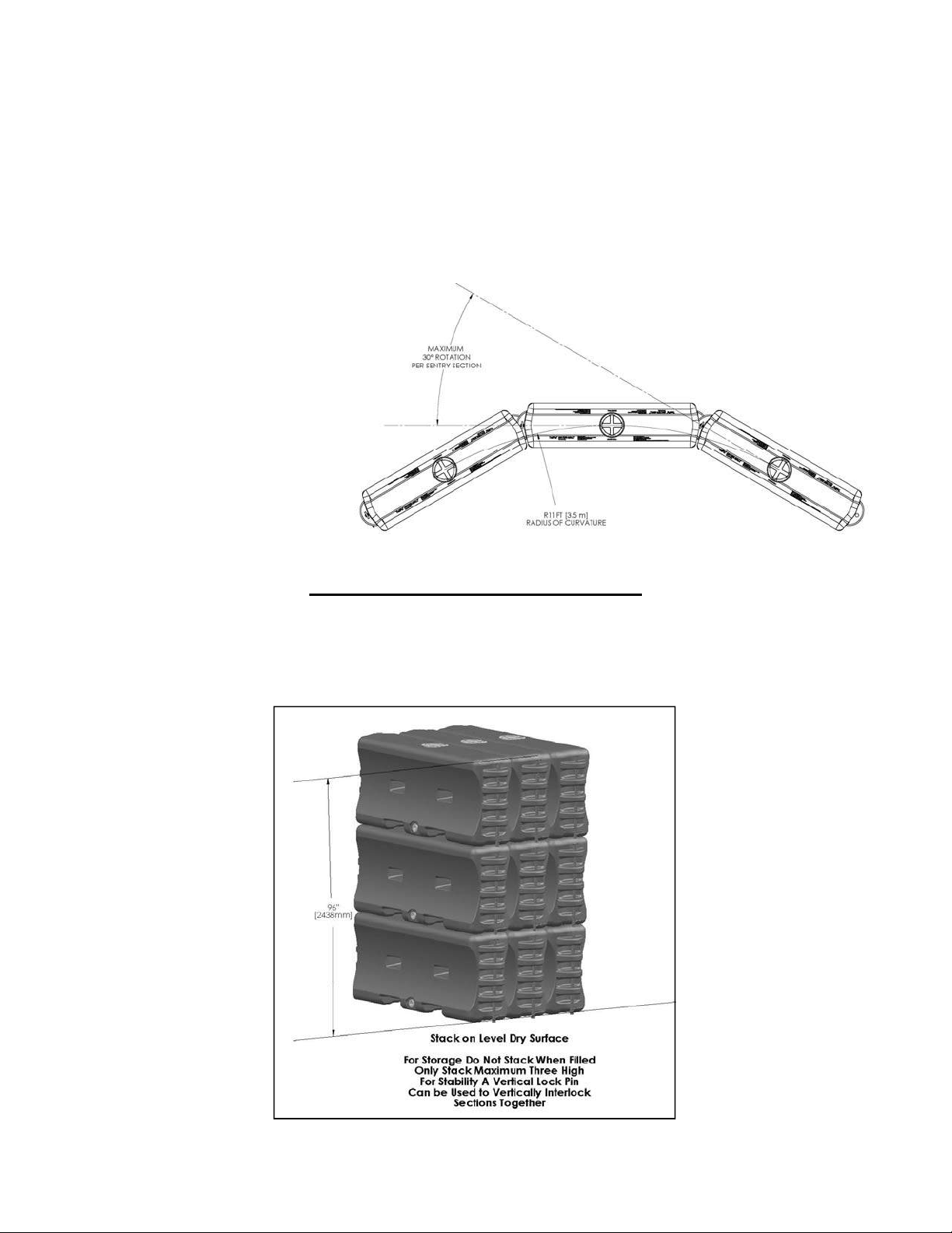
Angle of Rotation
The TrafFix Water-Wall is
designed to have maximum angle
of rotation of 30° when linked
together as seen in Figure 3 (or on
pg. 17). When fully rotated at the
maximum angle of rotation, the
linked TrafFix Water-Wall section
can be set-up with a minimum
inside radius of 11 ft. [3.5 m] as
seen in Figure 3.
Figure 3: Angle of Rotation TrafFix Water-Walls Linked
Recommendations for Stacking
The TrafFix Water-Walls must only be stacked when empty and are not designed to be stacked on each
other when filled. It is recommended to stack the empty TrafFix Water-Walls no more than three high
as seen in Figure 4 (or on pg. 18). For additional support, a long T-pin can be inserted into the
knuckles to secure the Sentry as seen in Figure 4.
Figure 4: TrafFix Water-Walls Stacking Diagram for Long Term Storage Requirements
Revision A (Dated 05/01/13) 4

Deflection Clear Zone
When installing the TrafFix Water-Wall , a clear zone must be made kept on the work zone side of
the barrier to allow for lateral deflection into the work zone. When impacted at the design speed of
31 mph [50 kph] at an impact angle of 25° with a 4500 lbs. [2000 kg] impact vehicle the deflection is
15.5 ft. [4.7 m]. This is the minimum clear zone required in the work zone. This clear zone is at the
test impacted design speed and condition. Additional deflection values can be seen in Figure 5 (or on
pg. 19).
Figure 5: Clear Zone Diagram and Chart Recommendation
Maintenance and Repair
There are no scheduled maintenance requirements for the TrafFix Water-Wall. There should be
periodic checking of the water level to insure that it is filled to the proper level. The TrafFix WaterWall is not fully effective unless each section is filled. If the optional water level indicator is
installed, a visual inspection can be made while driving by, otherwise the fill cap should be removed
for inspection.
In a major impact, a severely damaged TrafFix Water-Wall should be removed and replaced. There
may be leaking sections that can be repaired following the steps below. See Figure 6 (or on pg. 20-
21)
Patching leaks (holes or cracks) in the TrafFix Water-Wall plastic should be done on completely dry
surfaces free of dirt and grease. In addition, any paint or added finish beyond the factory smooth
plastic surface should be removed.
Plastic welding and welding patches onto the surface is the most common method for repairing
leaking sections of the TrafFix Water-Wall. A plastic repair kit can be obtained from TrafFix Devices
Inc. The plastic patch is made from the same material as the TrafFix Water-Wall plastic. The
welding rod is made from the same material as the TrafFix Water-Wall plastic material as well. A
small butane or propane torch is used for applying heat to the plastic rod. The rod should be melted
to the patch and the wall surface in order to create a bonding patch. Temperature for bonding the
plastic is 500-550°F [260-290°C]. The torch head should be held ¼-½ inch [0.635-1.27 cm] away
Revision A (Dated 05/01/13) 5

from the weld surface. Care should be taken when applying heat to plastic to insure that the
melting occurs only as desired.
NOTE: Repairing a crack or hole DOES NOT return the plastic to its original strength,
although most repairs are sufficient to insure a water tight section. Monitoring of the repair
should be done for a short period after filling to insure that the repair has been done properly.
If leaks cannot be prevented, the section should be replaced.
In addition, if there has been an impact, the T-pins may be difficult to remove for wall realignment
since some sections have been compressed. A fork lift will facilitate wall realignment if necessary,
without removing the T-pins or to relieve the force on the T-pins. NOTE: When moving the full
water wall, use the two forklift pockets located at the bottom of the wall.
Figure 6: Clear Zone Diagram and Chart Recommendation
Revision A (Dated 05/01/13) 6

Water Freezing Prevention
In freezing weather conditions, allowing the water in TrafFix Water-Wall to freeze to a solid mass of
ice should not be allowed. If the temperature at the TrafFix Water-Wall site is expec ted to be at or
below the freezing point of water, it is recommended that an additive be used to prevent the water in
the TrafFix Water-Wall from freezing.
-Common additives used to prevent water freezing currently used in work zone devices
under the same category as the TrafFix Water-Wall.
SALT (Sodium Chloride)
20% mixture by weight
Reduces freezing down to 0° F [-18° C].
Corrosive to inadequately protected steel components (Galvanizing adequately prevents
corrosion)
Recommended - premix before filling
Prevent spilling since solution is harmful to vegetation, soils, and wildlife. Draining should be done
in an acceptable area.
CALCIUM CHLORIDE
35% mixture by weight
Reduces Freezing down to 20° F [ -6.6 °C ].
Corrosive to thin zinc plated components
Corrosive to inadequately protected steel components (Galvanizing adequately prevents
corrosion)
High tendency to stay on road surface resulting in slick road surface.
High level of heat created when mixing. It is recommended that pre-mixing is done before filling.
Prevent spilling since solution is harmful to vegetation, soils, and wildlife. Draining should be done
in an acceptable area.
ETHYLENE/PROPYLENE GLYCOL
50% mixture by volume
Reduces water freezing to 0° F [-18° C].
High tendency to stay on road surface resulting in slick road surface.
Prevent spilling since solution is harmful to vegetation, soils, and wildlife. Draining should be done
in an acceptable area.
LIQUID CMA (calcium magnesium acetate)
25% mixture by volume
Reduces water freezing to 0° F [-18° C].
Has a low environmental impact.
LIQUID POTASSIUM ACETATE
60% mixture by volume
Reduces water freezing to 20° F [-6.6° C]
Low corrosive characteristics and has a low environmental impact.
Revision A (Dated 05/01/13) 7
 Loading...